
Page 1
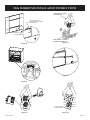
INSTALLATION INSTRUCTIONS
AND
OWNER’S MANUAL
POWER-VENT
HIGH-EFFICIENCY
FIREPLACE WITH
BAY WINDOW MODELS
BF28(B,C,G)M(N,P)-3
BI28(B,C,G)M(N,P)-3
BP28(B,C,G)M(N,P)-3
FLAT FRONT MODELS
FF28BM(N,P)-1
FI28BM(N,P)-1
FW28BM(N,P)-1
WARNING: If not installed, operated and maintained in
accordance with the manufacturer’s instructions, this
product could expose you to substances in fuel or from fuel
combustion which can cause death or serious illness.
Installer: Leave this manual with the appliance.
Consumer: Retain this manual for future reference.
— Donotstoreorusegasolineorotherammablevapors
and liquids in the vicinity of this or any other appli-
ance.
— WHAT TO DO IF YOU SMELL GAS
• Donottrytolightanyappliance.
• Donottouchanyelectricalswitch;donotuseany
phone in your building.
• Immediatelycallyourgassupplierfromaneigh-
bor’s phone. Follow the gas supplier’s instruc-
tions.
• Ifyoucannotreachyourgassupplier,callthere
department.
— Installation and service must be performed by a quali-
edinstaller,serviceagencyorthegassupplier.
WARNING: If the information in these instructions
arenotfollowedexactly, are orexplosionmayresult
causing property damage, personal injury or loss of life.
This appliance may be installed in an aftermarket,
permanently located, manufactured home (USA only) or
mobile home, where not prohibited by state or local codes.
This appliance is only for use with the type of gas indicated
on the rating plate. This appliance is not convertible for use
withothergases,unlessacertiedkitisused.
™
EMPIRE
EMPIRE
Comfor t Systems
Attention: This appliance may be installed in the U.S. and
Canada.
Young children should be carefully supervised when they
are in the same room as the appliance. Toddlers, young
children and others may be susceptible to accidental con-
tact burns. A physical barrier is recommended if there are
atriskindividualsinthehouse.Torestrictaccesstoare-
place or stove, install an adjustable safety gate to keep tod-
dlers, young children and other at risk individuals out of
the room and away from hot surfaces.
WARNING
HOT GLASS
DO NOT TOUCH
NEVER
WILL
CAUSE BURNS.
GLASS
UNTIL COOLED.
ALLOW CHILDREN
TO TOUCH GLASS.
Attention: Check local codes for venting requirements.

27020-3-0410Page 2
TABLE OF CONTENTS
Important Safety Information ....................................................................................................................................................................... 3
Safety Information for Users of LP-Gas ....................................................................................................................................................... 4
Requirements for Massachusetts ................................................................................................................................................................... 5
Gas Supply .................................................................................................................................................................................................... 6
Introduction ................................................................................................................................................................................................... 7
Installation Instructions – General Safety Information ................................................................................................................................. 8
Specications ................................................................................................................................................................................................ 8
Clearances for Single Flue ............................................................................................................................................................................. 9
Heater Installation for Single Flue ................................................................................................................................................................. 9
Clearances for Direct Vent ........................................................................................................................................................................... 10
Heater Installation for Direct Vent ............................................................................................................................................................... 10
Bay Window Specications .................................................................................................................................................................. 11 - 12
Flat Front Specications .............................................................................................................................................................................. 13
Bay Window Clearance to Combustibles .................................................................................................................................................... 14
Flat Front Clearance to Combustibles .......................................................................................................................................................... 15
Rough Framing Dimensions ........................................................................................................................................................................ 16
Insert Into Masonry Fireplace ...................................................................................................................................................................... 16
Bay Window Wall Clearances ...................................................................................................................................................................... 17
Flat Front Wall Clearances ........................................................................................................................................................................... 17
Bay Window Log Set Installation Instructions ............................................................................................................................................ 18
Flat Front Log Set Installation Instructions .......................................................................................................................................... 19 - 20
Vent Examples for Single Flue ............................................................................................................................................................. 20 - 22
Flex Vent Kit ................................................................................................................................................................................................ 23
Horizontal Vent Adaptor Kit ........................................................................................................................................................................ 24
Horizontal Examples for Colinear Direct Vent ............................................................................................................................................ 25
Vertical Examples for Colinear Direct Vent .......................................................................................................................................... 26 - 27
Horizontal Colinear Direct Vent Adaptor..................................................................................................................................................... 28
Termination Cap Vent .................................................................................................................................................................................. 29
Colinear Transition Vent Kit ........................................................................................................................................................................ 30
Direct Vent Installation Instructions ............................................................................................................................................................ 31
Vent Kit ................................................................................................................................................................................................. 32 - 33
Bay Window Gas Connection Installation Instructions ............................................................................................................................... 34
Flat Front Gas Connection Installation Instructions .................................................................................................................................... 35
F(F,I,W)K28(BL, CM, HP, SS)Surround Installation Instructions .............................................................................................................. 36
FGK Surround Installation Instructions ................................................................................................................................................ 36 - 37
Operating Instructions Checklist .................................................................................................................................................................. 38
Lighting Instructions ............................................................................................................................................................................... 39-40
Fan Operation ............................................................................................................................................................................................... 41
Automatic Humidier Operation ................................................................................................................................................................. 41
Optional Controllers .............................................................................................................................................................................. 42 - 43
Wiring .......................................................................................................................................................................................................... 44
General Information ..................................................................................................................................................................................... 45
Bay Window Maintenance .................................................................................................................................................................... 45 - 46
Flat Front Maintenance ......................................................................................................................................................................... 47 - 49
Unit Operating Faults ................................................................................................................................................................................... 50
Resetting the Heater ..................................................................................................................................................................................... 50
Log Placement ............................................................................................................................................................................................. 50
Main Convection Fan ................................................................................................................................................................................... 51
Heat Exchanger ............................................................................................................................................................................................ 51
Bay Window Surround Installation Instructions .......................................................................................................................................... 51
Pedestal Installation Instructions - Bay Window Only ................................................................................................................................ 52
Master Parts Distributor List ........................................................................................................................................................................ 53
How To Order Repair Parts .......................................................................................................................................................................... 53
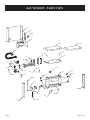
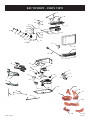
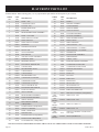
Bay Window Parts List ......................................................................................................................................................................... 54 - 55
Bay Window Exploded View ................................................................................................................................................................ 56 - 57
Flat Front Parts List ..................................................................................................................................................................................... 58
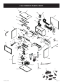
Flat Front Parts View ................................................................................................................................................................................... 59
Warranty Terms ............................................................................................................................................................................................ 60
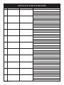
Appliance Service History .................................................................................................................................................................... 61- 63
SECTION PAGE

27020-3-0410 Page 3
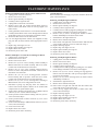
IMPORTANT SAFETY INFORMATION
THIS IS A HEATING APPLIANCE
DO NOT OPERATE THIS APPLIANCE WITHOUT FRONT PANEL INSTALLED.
• Due to high temperatures the appliance should be
located out of trafc and away from furniture and
draperies.
• Children and adults should be alerted to the hazards
of high surface temperatures and should stay away to
avoid burns or clothing ignition.
• Young children should be carefully supervised when
they are in the same room as the appliance. Toddlers,
young children and others may be susceptible to acci-
dental contact burns. A physical barrier is recommend-
ed if there are at risk individuals in the house. To restrict
accesstoareplaceorstove,installanadjustablesafety
gate to keep away toddlers, young children and other
at risk individuals out of the room and away from hot
surfaces.
• Clothing or other ammable material should not be
placed on or near the appliance.
• Any safety screen or guard removed for servicing an
appliance must be replaced prior to operating the
appliance.
• Keepburnerandcontrolcompartmentclean.
• Ventcaphotwhilefurnaceisinoperation.
• For manufactured home (USA only) or mobile home
or residential installation convertible for use with
natural gas and liqueed petroleum gases when
provision is made for the simple conversion from one
gas to the other.
• Installation and repair should be done by a
QUALIFIED SERVICE PERSON. The appliance
should be inspected before use and at least annually
by a qualied service person. More frequent cleaning
may be required due to excessive lint from carpeting,
bedding materials, etc. It is imperative that control
compartments, burners and circulating air passageways
of the appliance be kept clean.
• DO NOT put anything around the furnace that will
obstructtheowofcombustionandventilationair.
• DO keep the appliance area clear and free from
combustible material, gasoline and other ammable
vapors and liquids.
• Do examine venting system periodically and replace
damaged parts.
• Domakeaperiodicvisualcheckofburner.Cleanand
replace damaged parts.
• DO NOT use this heater if any part has been under
water. Immediately call a qualied service technician
to inspect the heater and to replace any part of the
control system and any gas control which has been
under water.

27020-3-0410Page 4
SAFETY INFORMATION FOR USERS OF LP-GAS
Propane (LP-Gas) is a ammable gas which can cause res and
explosions. In its natural state, propane is odorless and colorless.
You may not know all the following safety precautions which can
protect both you and your family from an accident. Read them
carefully now, then review them point by point with the mem-
bers of your household. Someday, there may not be a minute to
lose, everyone’s safety will depend on knowing exactly what to
do. If, after reading the following information, you feel you still
need more information, please contact your gas supplier.
LP-GAS WARNING ODOR
If a gas leak happens, you should be able to smell the gas because of the odorant put in the LP-Gas.
That’s your signal to go into immediate action!
• Do not operate electric switches, light matches, use your
phone. Do not do anything that could ignite the gas.
• Get everyone out of the building, vehicle, trailer, or area. Do
that IMMEDIATELY.
• Close all gas tank or cylinder supply valves.
• LP-Gas is heavier than air and may settle in low areas such
as basements. When you have reason to suspect a gas leak,
keep out of basements and other low areas. Stay out until
reghters declare them to be safe.
• Use your neighbor’s phone and call a trained LP-Gas
service person and the re department. Even though you
may not continue to smell gas, do not turn on the gas again.
Do not re-enter the building, vehicle, trailer, or area.
• Finally, let the service man and reghters check for
escaped gas. Have them air out the area before you return.
Properly trained LP-Gas service people should repair the
leak, then check and relight the gas appliance for you.
NO ODOR DETECTED - ODOR FADE
Some people cannot smell well. Some people cannot smell the
odor of the chemical put into the gas. You must nd out if you
can smell the odorant in propane. Smoking can decrease your
ability to smell. Being around an odor for a time can affect your
sensitivity or ability to detect that odor. Sometimes other odors
in the area mask the gas odor. People may not smell the gas odor
or their minds are on something else. Thinking about smelling a
gas odor can make it easier to smell.
The odorant in LP-gas is colorless, and it can fade under some
circumstances. For example, if there is an underground leak, the
movement of the gas through soil can lter the odorant. Odorants
in LP-Gas also are subject to oxidation. This fading can occur if
there is rust inside the storage tank or in iron gas pipes.
The odorant in escaped gas can adsorb or absorb onto or into
walls, masonry and other materials and fabrics in a room. That
will take some of the odorant out of the gas, reducing its odor
intensity.
LP-Gas may stratify in a closed area, and the odor intensity
could vary at different levels. Since it is heavier than air, there
may be more odor at lower levels. Always be sensitive to the
slightest gas odor. If you detect any odor, treat it as a serious leak.
Immediately go into action as instructed earlier.
SOME POINTS TO REMEMBER
• Learn to recognize the odor of LP-gas. Your local LP-Gas
Dealer can give you a “Scratch and Sniff” pamphlet. Use it
to nd out what the propane odor smells like. If you suspect
that your LP-Gas has a weak or abnormal odor, call your
LP-Gas Dealer.
• If you are not qualied, do not light pilot lights, perform
service, or make adjustments to appliances on the LP-Gas
system. If you are qualied, consciously think about the
odor of LP-Gas prior to and while lighting pilot lights or
performing service or making adjustments.
• Sometimes a basement or a closed-up house has a musty
smell that can cover up the LP-Gas odor. Do not try to light
pilot lights, perform service, or make adjustments in an area
where the conditions are such that you may not detect the
odor if there has been a leak of LP-Gas.
• Odor fade, due to oxidation by rust or adsorption on walls
of new cylinders and tanks, is possible. Therefore, people
should be particularly alert and careful when new tanks or
cylinders are placed in service. Odor fade can occur in new
tanks, or reinstalled old tanks, if they are lled and allowed
to set too long before relling. Cylinders and tanks which
have been out of service for a time may develop internal
rust which will cause odor fade. If such conditions are
suspected to exist, a periodic sniff test of the gas is
advisable. If you have any question about the gas odor, call
your LP-gas dealer. A periodic sniff test of the LP-gas is a
good safety measure under any condition.
• If, at any time, you do not smell the LP-Gas odorant and
you think you should, assume you have a leak. Then take
the same immediate action recommended above for the
occasion when you do detect the odorized LP-Gas.
• If you experience a complete “gas out,” (the container
is under no vapor pressure), turn the tank valve off
immediately. If the container valve is left on, the container
may draw in some air through openings such as pilot light
orices. If this occurs, some new internal rusting could
occur. If the valve is left open, then treat the container as
a new tank. Always be sure your container is under vapor
pressure by turning it off at the container before it goes com-
pletely empty or having it relled before it is completely
empty.

27020-3-0410 Page 5
REQUIREMENTS FOR MASSACHUSETTS
For all side wall horizontally vented gas fueled equipment installed
in every dwelling, building or structure used in whole or in part
for residential purposes, including those owned or operated by the
Commonwealth and where the side wall exhaust vent termination
is less than seven (7) feet above nished grade in the area of
the venting, including but not limited to decks and porches, the
following requirements shall be satised:
1. INSTALLATION OF CARBON MONOXIDE DETECTORS.
At the time of installation of the side wall horizontal vented
gas fueled equipment, the installing plumber or gastter shall
observe that a hard wired carbon monoxide detector with an
alarm and battery back-up is installed on the oor level where
the gas equipment is to be installed. In addition, the installing
plumber or gastter shall observe that a battery operated
or hard wired carbon monoxide detector with an alarm is
installed on each additional level of the dwelling, building or
structure served by the side wall horizontal vented gas fueled
equipment. It shall be the responsibility of the property owner
to secure the services of qualied licensed professionals for
the installation of hard wired carbon monoxide detectors
a. In the event that the side wall horizontally vented gas
fueled equipment is installed in a crawl space or an attic,
the hard wired carbon monoxide detector with alarm and
battery back-up may be installed on the next adjacent
oor level.
b. In the event that the requirements of this subdivision can
not be met at the time of completion of installation, the
owner shall have a period of thirty (30) days to comply
with the above requirements; provided, however, that
during said thirty (30) day period, a battery operated
carbon monoxide detector with an alarm shall be
installed.
2. APPROVED CARBON MONOXIDE DETECTORS. Each
carbon monoxide detector as required in accordance with the
above provisions shall comply with NFPA 720 and be ANSI/
UL 2034 listed and IAS certied.
3. SIGNAGE. A metal or plastic identication plate shall be
permanently mounted to the exterior of the building at a
minimum height of eight (8) feet above grade directly in line
with the exhaust vent terminal for the horizontally vented gas
fueled heating appliance or equipment. The sign shall read,
in print size no less than one-half (1/2) inch in size, “GAS
VENT DIRECTLY BELOW. KEEP CLEAR OF ALL
OBSTRUCTIONS”.
4. INSPECTION. The state or local gas inspector of the side
wall horizontally vented gas fueled equipment shall not
approve the installation unless, upon inspection, the inspector
observes carbon monoxide detectors and signage installed in
accordance with the provisions of 248 CMR 5.08(2)(a) 1
through 4.
(b) EXEMPTIONS: The following equipment is exempt
from 248 CMR 5.08(2)(a)1 through 4:
1. The equipment listed in Chapter 10 entitled
“Equipment Not Required To Be Vented” in the
most current edition of NFPA 54 as adopted by the
Board; and
2. Product Approved side wall horizontally vented gas
fueled equipment installed in a room or structure
separate from the dwelling, building or structure
used in whole or in part for residential purposes.
(d) MANUFACTURER REQUIREMENTS - GAS
EQUIPMENT VENTING SYSTEM NOT PROVIDED.
When the manufacturer of a Product Approved side
wall horizontally vented gas fueled equipment does not
provide the parts for venting the ue gases, but identies
“special venting systems”, the following requirements
shall be satised by the manufacturer:
1. The referenced “special venting system” instructions
shall be included with the appliance or equipment
installation instructions; and
2. The “special venting systems” shall be Product
Approved by the Board, and the instructions for
that system shal include a parts list and detailed
installation instruction.
(e) A copy of all installation instructions for all Product
Approved side wall horizontally vented gas fueled
equipment, all venting instructions, all parts lists for
venting instructions, and/or all venting design instructions
shall remain with the appliance or equipment at the
completion of the installation.

27020-3-0410Page 6
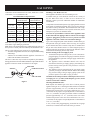
Consult the current National Fuel Gas Code, ANSI Z223.1 CAN/
CGA-B149 (.1 or .2) installation code.
Recommended Gas Pipe Diameter
Pipe Length Schedule 40 Pipe
Inside Diameter
Tubing, Type L
Outside Diameter
Nat. L.P. Nat. L.P.
0-10 feet
0-3 meters
1/2”
12.7mm
3/8”
9.5 mm
1/2”
12.7mm
3/8”
9.5 mm
10-40 feet
4-12 meters
1/2”
12.7mm
1/2”
12.7mm
5/8”
15.9 mm
1/2”
12.7mm
40-100 feet
13-30 meters
1/2”
12.7mm
1/2”
12.7mm
3/4”
19mm
1/2”
12.7mm
100-150 feet
31-46 meters
3/4”
19mm
1/2”
12.7mm
7/8”
22.2 mm
3/4”
19mm
Note: Never use plastic pipe. Check to conrm whether your local
codes allow copper tubing or galvanized.
Note: Since some municipalities have additional local codes, it is
always best to consult your local authority and installation code.
The use of the following gas connectors is recommended:
— ANS Z21.24 Appliance Connectors of Corrugated Metal Tubing
and Fittings
— ANS Z21.45 Assembled Flexible Appliance Connectors of
Other Than All-Metal Construction
The above connectors may be used if acceptable by the authority
having jurisdiction. The state of Massachusetts requires that a exible
appliance connector cannot exceed three feet in length.
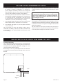
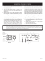
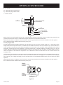
Figure 1
Installing a New Main Gas Cock
Each appliance should have its own manual gas cock.
A manual main gas cock should be located in the vicinity of
the unit. Where none exists, or where its size or location is not
adequate, contact your local authorized installer for installation
or relocation.
Compounds used on threaded joints of gas piping shall be resistant
to the action of liqueed petroleum gases. The gas lines must be
checked for leaks by the installer. This should be done with a soap
solution watching for bubbles on all exposed connections, and if
unexposed, a pressure test should be made.
Neveruseanexposedametocheckforleaks.Appliancemust
be disconnected from piping at inlet of control valve and pipe
capped or plugged for pressure test. Never pressure test with
applianceconnected;controlvalvewillsustaindamage!
A gas valve and ground joint union should be installed in the gas
line upstream of the gas control to aid in servicing. It is required
by the National Fuel Gas Code that a drip line be installed near
the gas inlet. This should consist of a vertical length of pipe tee
connected into the gas line that is capped on the bottom in which
condensation and foreign particles may collect.
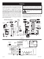
Pressure Testing of the Gas Supply System
1. To check the inlet pressure to the gas valve, a 1/8" (3 mm) N.P.T.
plugged tapping, accessible for test gauge connection, must be
placed immediately upstream of the gas supply connection to
the appliance.
2. The appliance and its individual shutoff valve must be
disconnected from the gas supply piping system during any
pressure testing of that system at test pressures in excess of
1/2 psig (3.5 kPa).
3. The appliance must be isolated from the gas supply piping
system by closing its individual manual shutoff valve during
any pressure testing of the gas supply piping system at test
pressures equal to or less than 1/2 psig (3.5 kPa).
Attention! If one of the procedures results in pressures in excess
of1/2psig(14"w.c.)(3.5kPa)onthereplacegasvalve,itwill
resultinahazardouscondition.
Checking Manifold Pressure
Both Propane and Natural gas valves have a built-in pressure
regulator in the gas valve. Natural gas models will have a manifold
pressure of approximately 3.5" w.c. (.872 kPa) at the valve outlet
with the inlet pressure to the valve from a minimum of 5.0" w.c.
(1.245 kPa) for the purpose of input adjustment to a maximum of
10.5" w.c. (2.614 kPa) Propane gas models will have a manifold
pressure approximately 7.0" w.c. (2.49 kPa) at the valve outlet
with the inlet pressure to the valve from a minimum of 11.0" w.c.
(2.739 kPa) for the purpose of input adjustment to a maximum of
13.0" w.c. (3.237 kPa).
A 1/8" (3 mm) N.P.T. plugged tapping, accessible for test gauge
connection, is located on the outlet side of the gas control.
GAS SUPPLY
FLEX TUBING
3/8 NPT
NIPPLE
FLARE FITTING
GAS VA LV E
SOLENOID
FLARE SHUT OFF VA LV E

27020-3-0410 Page 7
QualiedInstallingAgency
Installation and replacement of gas piping, gas utilization
equipment or accessories and repair and servicing of equipment
shall be performed only by a qualied agency. The term “quali-
ed agency” mean any individual, rm, corporation or company
which either in person or through a representative is engaged in
and is responsible for (a) the installation or replacement of gas
piping or (b) the connection, installation, repair or servicing of
equipment, who is experienced in such work, familiar with all
precautions required and has complied with all the requirements
of the authority having jurisdiction.
The installation must conform with local codes, or in the absence
of local codes, the National Fuel Gas Code, ANSI Z223.1/NFPA
54 or Natural Gas and Propane Installation Code, CSA B149.1.
* Available from the American National Standards Institute, Inc.,
11 West 42nd St., New York, NY 10036.
A manufactured home (USA only) or mobile home OEM
installation must conform with the Manufactured Home
Construction and Safety Standard, Title 24 CFR, Part 3280, or,
when such a standard is not applicable, the Standard for Manu-
factured Home Installations, ANSIZ225.1, or Standard for Gas
Equipped Recreational Vehicles and Mobile Housing, CSA
Z240.0.
High Altitudes
For altitudes/elevations above 2,000 feet (610 m), input ratings
should be reduced at the rate of 4 percent for each 1,000 feet
(305 m) above sea level, this may be accomplished by reducing
manifold pressure. The maximum allowable reduction in manifold
pressure for Natural gas shall be from 3.5” w.c. (.872 kPa) to 2.8”
w.c. (.697 kPa). The maximum allowable reduction in manifold
pressure for Propane (LP) gas shall be from 10.0” w.c. (2.49 kPa)
to 8.0” w.c. (1.99 kPa). For Canadian high altitude applications,
this appliance is suitable for installation at elevations between
0 feet (0 m) and 4,500 feet (1,372 m) without change.
Canada:
This appliance may be installed in Canada.
Introduction
Always consult your local Building Department regarding
regulations, codes or ordinances which apply to the installation of
a direct vent wall furnace.
Instructions to Installer
1. Installer must leave instruction manual with owner after
installation.
2. Installer must have owner ll out and mail warranty card
supplied with furnace.
3. Installer should show owner how to start and operate furnace
and thermostat.
4. Installer must locate unit near a grounded wall receptacle for
115VAC power and must provide gas supply and vent the
unit properly for safe operation.
General Information
This series is designed certied in accordance with American
National Standard/CSA Standard Z21.88 and CSA 2.33 by the
Canadian Standards Association as a Gas Fireplace Heater to be
installed according to these instructions.
Any alteration of the original design, installed other than as
shown in these instructions or use with a type of gas not shown
on the rating plate is the responsibility of the person and
company making the change.
Important
All Correspondence should refer to complete Model Number,
Serial Number and type of gas.
Notice: During initial ring of this unit, oil from the heat
exchanger may bake out and smoke may occur. To prevent trig-
gering of smoke alarms, ventilate the room in which the unit is
installed.
Installation in Residential Garages
Gas utilization equipment in residential garages shall be installed
so that all burners and burner ignition devices are located not less
than 18” (457 mm) above the oor.
Such equipment shall be located, or protected, so it is not subject
to physical damage by a moving vehicle.
Warning:
Any change to this furnace or its control can be dangerous.
This is a heating appliance and any panel, door or guard
removed for servicing an appliance must be replaced prior
to operating the appliance.
Sate of Massachusetts: The installation must be made by a
licensed plumber or gas tter in the Commonwealth of Mas-
sachusetts.
INTRODUCTION

27020-3-0410Page 8
Bay Window Models B(F,I,P)28(B,C,G)M
Input BTU/HR (KW/H) 19,000 Rear - 9,000 Front
Height 25 1/8”
Width 28 3/16”
Depth 17 5/8”
Gas Inlet (Pipe) 3/8” Flair
Electrical - Unit has a 5’ (1.5 m) 3 pronged cordset for con-
nection to an approved 115 VAC 60 Hz maximum
AMPs - 5A wall receptacle.
SPECIFICATIONS
INSTALLATION INSTRUCTIONS - GENERAL SAFETY INFORMATION
1. This installation must conform with local codes or, in the
absence of local codes with NFPA54.
2. Provide adequate clearances around the product for servicing
and ensure there are no obstructions to the combustion air
intake situated at the back of the heater. Refer to Pages 14 and
15.
3. The appliance must be installed on a at, solid continuous
surface (i.e. wood, metal, concrete). Please Note: Rough
or uneven surfaces can cause vibration or humming in the
heater.
4. The Mantis Power-Vent High-Effeciency Fireplace can be
installed in a wide variety of ways and will t nearly any
room layout. For installation options refer to Pages 14 and
15.
5. This appliance (Insert and Freestanding Models) needs to be
installed in such a way that the heater can be removed at all
times to service the heater exchanger and ue fan located in
the rear section of the heater.
Note: Under no circumstances should the appliance be
installed under conditions which would not allow for
easy removal of the appliance to carry out routine
inspection and service to the appliance, to do so will
void the warranty.
Note: On Single Wall ue pipe installations (imitation
zero clearance replace) a minimum of 2” (50.8 cm)
clearance must be provided at the rear of the heater to
enable the heater to get sufcient combustion air to the
air inlet located at the rear of heater. Refer to installation
instructions on Pages 14 and 15.
Note: Where a mantel surround is being used on insert
installations and zero clearance replace installations,
the combustion air intake slot located in the top mantel
surround must have no obstructions to allow combustion
air to enter through the slot to the combustion air inlet
located at the back of the heater.
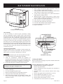
Flat Front Models F(F,I,W)28BM(N,P)
Input BTU/HR (KW/H) 15,000 Rear - 13,000 Front
Height 24 9/16”
Width 28”
Depth 17 3/16”
Gas Inlet (Pipe) 3/8” Flair
Electrical - Unit has a 5’ (1.5 m) 3 pronged cordset for con-
nection to an approved 115 VAC 60 Hz maximum
AMPs - 5A wall receptacle.
Accessories
Common
Part Number Description
FRBTC Battery Operated Remote with Thermostat
FRBTP
Battery Operated Remote with Programmable
Thermostat
PVCA Colinear Adapter
PVCT Colinear Transition
PVVK24H Direct Vent 24” Vent Kit
PVVK48H Direct Vent 48” Vent Kit
PVVK-CFA Flex Vent Kit
PVVK-SH Single Flue Horizontal Vent Kit
PVVK-SV Single Flue Vertical Vent Kit
PVVTC Vertical Termination Cap - 1.5”
T24V 24 Volt Thermostat
TMV2 Two-Stage Thermostats
TRW Wall Thermostat - Wireless Remote
TDV1 Wall Thermostat - Wireless Remote
Bay Window
CIFPB-1C Corner Floor Pad Kit
CIPFP-1 Floor Pad Kit
PV-2H Top Cover - Slim Assembly
PV-4H Top Cover - Short Assembly
PVE-1 6” Surround Assembly
PVPK Pedestal Kit
PVSH Rear Shroud
TRW Wall Thermostat - Wireless Remote

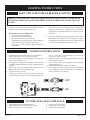
27020-3-0410 Page 9
1. Pick a location on a wall with a clear space in the room.
In selecting a location for installation, it is necessary to
provide adequate accessibility clearances for servicing and
proper installation. Be sure to locate the unit close enough to a
115 VAC wall receptacle to properly power appliance.
2. When facing the front of the furnace, the minimum clearances
from casing to combustible construction are 0” (0 mm) on top,
0” (0 mm) on each side, recommend 4” (102 mm) for servicing
and 0” (0 mm) from the oor and 2” (51 mm) to rear wall for
servicing and installation.
3. The minimum distance from the center of the vent cap to the
nearest outside corner or obstruction is 12” (305 mm).
The bottom of the exhaust vent terminal and the air intake shall
be located at least 12” (305 mm) above grade and must be vented
outside.
WARNING: The nearest point of the vent cap should be a
minimumhorizontaldistanceofsix(6)feet(1.83m)from
any pressure regulator. In case of regulator malfunction,
thesix(6)feet(1.83m)distancewillreducethechanceof
gas entering the vent cap.
Installation on Rugs and Tile
If this appliance is to be installed directly on carpeting, tile, or other
combustible material, other than wood ooring, the appliance shall
be installed on a metal or wood panel extending the full width and
depth of the appliance.
The base referred to above does not mean the re-proof base as
used on wood stoves. The protection is primarily for rugs that may
be extremely thick and light-color tile that can discolor.
Locating Wall Opening
The recommended location for this heater is on an outside wall
(the unit can be located on an inside wall but must not exceed 40’
(12.19 m) in exhaust vent length). Locate wall studs so that wall
vent opening will be located between wall studs. The wall opening
required for venting is a 1 7/8” (48 mm) minimum diameter
opening.
Refer to Pages 11 to 17 for positioning the heater on wall and for
locating gas line connection and vent opening. Heater can sit on
the oor.
CLEARANCES FOR SINGLE FLUE
HEATER INSTALLATION FOR SINGLE FLUE

27020-3-0410Page 10
1. Pick a location on a wall with a clear space in the room.
In selecting a location for installation, it is necessary to
provide adequate accessibility clearances for servicing and
proper installation. Be sure to locate the unit close enough to a
110 VAC wall receptacle to properly power appliance.
2. When facing the front of the furnace the minimum clearances
from casing to combustible construction are 0” (0 mm) on top,
0” (0 mm) on each side, recommend 4” (102 mm) on sides
for servicing and 0” (0 mm) from the oor, 0” (0 mm) to rear
wall and 40” (1,016 mm) from Mantis top to ceiling.
3. The minimum distance from the center of the vent cap to the
nearest outside corner or obstruction is 12” (305 mm).
4. The minimum wall depth is 4” (102 mm) and the maximum
is 48” (121.92 cm).
The vent terminal of a direct vent appliance, with an input of
50,000 BTU (14.6KW) per hour or less shall be located at least
9” (229 mm) from any opening through which ue gases could
enter a building.
The bottom of the exhaust vent terminal and the air intake shall
be located at least 12” (305 mm) above grade and must be vented
outside.
WARNING: The nearest point of the vent cap should be
aminimumhorizontaldistantofsix(6)feet(1.83m)from
any pressure regulator. In case of regulator malfunction,
thesix(6)feet(1.83m)distancewillreducethechanceof
gas entering the vent cap.
Installation on Rugs and Tile
If this appliance is to be installed directly on carpeting, tile, or other
combustible material, other than wood ooring, the appliance shall
be installed on a metal or wood panel extending the full width and
depth of the appliance.
The base referred to above does not mean the re-proof base as
used on wood stoves. The protection is primarily for rugs that may
be extremely thick and light-color tile that can discolor.
Locating Wall Opening
The recommended location for this furnace is on an outside wall.
Locate wall studs so that wall vent opening will be located between
wall studs. The wall opening required for venting is a 3 1/2”
(89 mm) minimum diameter opening.
Refer to Pages 11 to 17 for positioning the heater on wall and for
locating gas line connection and vent opening. Furnace can sit on
the oor.
CLEARANCES FOR DIRECT VENT
HEATER INSTALLATION FOR DIRECT VENT
1 9/16”
4 3/32”
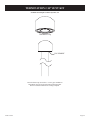
Figure 2

27020-3-0410 Page 11
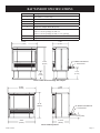
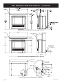
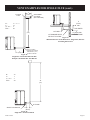
BAY WINDOW SPECIFICATIONS
28 3/16”
(71.6cm)
33 3/4”
(85.7cm)
8 5/8”
(21.9cm)
17 5/8”
(44.8cm)
5 - SINGLE FLUE ADAPTOR
12 1/4”
(31.1cm)
1 - FLUE OUTLET
Heater with Pedestal and Single Flue Adaptor
28 3/16”
(71.6cm)
25 1/8”
(63.8cm)
27 3/4”
(70.5cm)
17 5/8”
(44.8cm)
3 9/16” (9.0cm)
16 15/16”
(43.0cm)
1 - FLUE OUTLET
5 - SINGLE FLUE ADAPTOR
Heater without pedestal
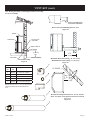
Index No. Description
1 Flue Outlet 1 1/2” PVC Pipe
2 Air Inlet
3 Electric Cord
4 3/8” Flare Connection (Inside)
5 Single Flue Adaptor Model (Required)
6 Surround
PVE1-1 Used on openings less than 35”
PVE2-1 Used on openings less than 37 1/2” openings
7 Top Cover Kit, Slim Model #PV2H
8 Top Cover Kit, Short

27020-3-0410Page 12
Rear View (Same with or without pedestal and all tops)
35 7/16”
(90.0cm)
29 3/4”
(75.6cm)
5 15/16” (15.1cm)
23 13/16”
(60.5cm)
10 1/8”
(25.7cm)
6 3/16”
(15.7cm)
3 9/16” (9.0cm)
16 15/16”
(43.0cm)
6 - SURROUND
ASSEMBLY
1 - FLUE
OUTLET
13/16” (2.1cm)
2 - AIR INLET
7 9/16”
(19.2cm)
2 13/16”
(7.1cm)
1 7/16”
(3.7cm)
4 - ½” FLARE
CONNECTION
INSIDE
6 1/8”
(15.6cm)
1 ½”
(3.8cm)
3 9/16”
(9.0cm)
1”
(2.5cm)
3 - ELECTRIC
CORD
8 -TOP COVER KIT,
SHORT
1 - FLUE OUTLET
5 - SINGLE FLUE
ADAPTOR
LOUVER
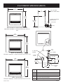
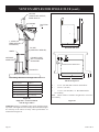
BAY WINDOW SPECIFICATIONS - (continued)
Fireplace Insert with Mantel Surround with Slim Top Panel
Fireplace Insert with Mantel Surround with Short Top Panel
35 7/16”
(90.0cm)
29 3/4”
(75.6cm)
5 15/16” (15.1cm)
23 13/16”
(60.5cm)
10 1/8”
(25.7cm)
6 3/16”
(15.7cm)
3 9/16” (9.0cm)
16 15/16”
(43.0cm)
6 - SURROUND
ASSEMBLY
1 - FLUE
OUTLET
13/16” (2.1cm)
2 - AIR INLET
7 9/16”
(19.2cm)
2 13/16”
(7.1cm)
1 7/16”
(3.7cm)
4 - ½” FLARE
CONNECTION
INSIDE
6 1/8”
(15.6cm)
1 ½”
(3.8cm)
3 9/16”
(9.0cm)
1”
(2.5cm)
3 - ELECTRIC
CORD
8 -TOP COVER KIT,
SHORT
1 - FLUE OUTLET
5 - SINGLE FLUE
ADAPTOR
LOUVER

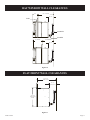
27020-3-0410 Page 13
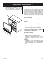
FLAT FRONT SPECIFICATIONS
35”
(88.9cm)
33 7/16”
(84.9cm)
35”
(88.9cm)
29 3/8”
(74.6cm)
38”
(96.5cm)
30 7/8”
(78.4cm)
1 - FLUE
OUTLET
2 - AIR INLET
3 - ELECTRIC
CORD
4 - FLEX HOSE
OPENING
1 1/8” (2.8cm)
7 5/16”
(18.6cm)
4 3/16”
(10.6cm)
2 5/8”
(6.7cm)
6 1/8”
(15.6cm)
3 9/16”
(9.0cm)
13/16”
(2.1cm)
1” (2.5cm)
17”
(43.2cm)
3 9/16” (9.0cm)
1 - FLUE OUTLET
5 - SINGLE FLUE ADAPTOR
MODEL #PVVK-SH
6 1/2” (16.5cm) MIN.
WITH 90° STREET ELBOW
24 3/4” MIN
(62.8cm)
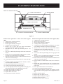
Index
No.
Description
1 Flue Outlet 1 1/2” PVC Pipe
2 Air Inlet
3 Electric Cord
4 3/8” Flare Connection (Inside)
5 Single Flue Adaptor Model #PVVK-SH (required)
Heater In Wall - 35” Picture Frame Surround
FWK28(BL,CM,HP,SS) - Contains surround, hood, and lower
front
Heater-35”SurroundKit
FFK28(BL,CM,HP,SS) - Contains surround, hood, & lower front
Heater - 38” Surround
FIK28(BL,CM,HP,SS) - Contains surround, hood, & lower front

27020-3-0410Page 14
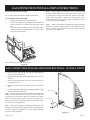
BAY WINDOW CLEARANCE TO COMBUSTIBLES
Freestanding Models
Freestanding Units
A Rear Wall to Heater 0” (2” Single Flue and 1 1/4” Direct Vent for Serviceability)
B Side Wall to Heater 0” (4” recommended for serviceability)
C Corner Installation 0”
D Mantel Clearance See Figure 7
Fireplace Insert
Note: The Mantis Power-Vent High-Efciency Fireplace has been tested and approved for zero clearance to combustible materials.
Empire Comfort Systems, Inc. recommends that clearances as listed above should be maintained to allow for removal of the
product for servicing.
C
C
A
BB
Figure 3 Figure 4
Single Flue
Requires surround for combustion air.
Do not cover surround louver.
Figure 5
33 1/4”
(84.5cm)
29 3/4”
(75.6cm)
12”
(30.5cm)
26 ½”
(67.3cm)
35 7/16”
(90.0cm)
WALL OPENING
D
LOUVER
Mantel and Ceiling Clearances
Figure 7
Direct Vent Installation Shown
Single Flue requires surround for combustion air.
Figure6
12”
18”
24”
8”
6”
4”
COMBUSTIBLE TRIM AND MANTELS
ALLOWED IN SHADED AREA
40”
CEILING

27020-3-0410 Page 15
FLAT FRONT CLEARANCE TO COMBUSTIBLES
Insert Models
Freestanding Units
A Rear Wall to Heater 0” (2” Single Flue and 1 1/4” Direct Vent for Serviceability)
B Side Wall to Heater 0”
C Corner Installation 0”
D Mantel Clearance See Figure 12
Fireplace Insert
Note: The Mantis Power-Vent High-Efciency Fireplace has been tested and approved for zero clearance to combustible materials.
Empire Comfort Systems, Inc. recommends that clearances as listed above should be maintained to allow for removal of the
product for servicing.
Figure 8 Figure 10
Single Flue
Requires surround for combustion air.
Do not cover surround louver.
Figure 11
37”
(93.98 cm)
30 7/8”
(78.4cm)
12”
(30.5cm)
26 ½”
(67.3cm)
38”
(96.5cm)
WALL OPENING
D
Mantel and Ceiling Clearances
Figure 12
A
A
BB
6 1/4”
MIN
C
C
Figure 9
12”
18”
24”
8”
6”
4”
COMBUSTIBLE TRIM AND MANTELS
ALLOWED IN SHADED AREA
44 3/4”
CEILING
4 3/4”

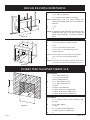
27020-3-0410Page 16
ROUGH FRAMING DIMENSIONS
A
B
C
ACCESS
PANELS
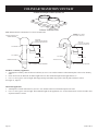
INSERT INTO MASONRY FIREPLACE
BAY WINDOW
A - 13 /34” MIN. CO-LINEAR
8 1/2” WHEN USING DIRECT VENTING
NOTE: DIMENSIONS FOR USE WITH SHORT TOP.
THIS IS RECOMMENDED FOR UNIT SERVICE-
ABILITY.
B - 25 1/8”
C - 28”
NOTE: IF TRIM AROUND HEATER IS NECESSARY, THE
SURROUND KIT PVE1-1 OR PVE2-1 MUST BE
USED, AND SUBTRACT 1” FROM (A) DIMEN-
SION.
BAY WINDOW
A - 12 3/4” MIN. SHORT TOP
17 13/16” MIN. SLIM TOP
USING SURROUND KIT
B - 25 1/8” MIN. DIRECT VENT
26 1/2” MIN. SINGLE FLUE
29” MAX
C - 28” MIN. NO SURROUND
33” MIN. WITH PVE-1 SURROUND
35” MAX. WITH PVE-1 SURROUND
37” MAX. WITH PVE2-1 SURROUND
Figure 15
Figure 13
FLAT FRONT
A - 23 1/2” WHEN USING FI28(BL,CM,HP,SS) SUR-
ROUND
B - 24 3/4” MIN. DIRECT
29” MAX
C - 28 3/16” MIN. WITH SURROUND
37” MAX. WITH 38” SURROUND
D - 4”
Figure 14
ACCESS
PANELS
1.5”
FLAT FRONT
A - 23 1/2” MIN. WITH 90° STREET ELBOW
B - 24 3/4”
27 3/4” IF FGK SURROUND IS USED
C - 28 3/16” MIN., 31” RECOMMENDED FOR
SERVICEABILITY.
NOTE: HEATER WILL BE 0” CLEARANCE ON RIGHT
AND 3” ON LEFT FOR SERVICEABILITY.
D - 4” - 6”
NOTE: ONLY ONE ACCESS PANEL (FIGURE 14) IS NEED-
ED. INSTALLER TO DETERMINE BEST OPTION.

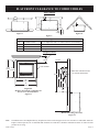
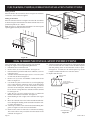
27020-3-0410 Page 17
BAY WINDOW WALL CLEARANCES
12 23/32”
6”
11 3/32”
17 13/16”
PVVK-CFA
PVVK-SH
PVE-1
6 ½”
6 ½”
Figure16
FLAT FRONT WALL CLEARANCES
Figure 17
23 1/2”
(59.7cm)
6 ½”
(16.5cm)
24 3/4”
(62.8cm)
MIN.

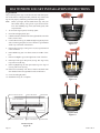
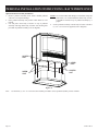
27020-3-0410Page 18
BAY WINDOW LOG SET INSTALLATION INSTRUCTIONS
Log Installation
The positioning of the logs is critical to the safe and clean opera-
tion of this heater. Sooting and other problems may result if the
logs are not properly and rmly positioned in the appliance.
Note: Before you begin: Do not handle these logs with your
bare hands! Always wear gloves to prevent skin irrita-
tion. After handling logs, wash your hands gently with
soap and water.
1. To access the log set parcel, lift off top panel.
2. Pivot left and right panels open.
3. Unlatch main door latches located on right and left side of the
heater, remove door.
4. Connect Rear Left Log (A) and Rear Right Log (B) at pins on
sides of each log and place in rear of burner. Logs should be
all the way to the back of the rebox.
5. Place Front Left Log (C) into groove on (A) Log and into left
corner of rebox.
6. Place Middle Log (D) over ame sensors in middle of re-
box.
7. Place Front Right Log (E) into right front corner of rebox.
8. Place Top Left Log (F) onto pin on (A) Log. The “legs” of (F)
Log will rest on (D) Log
9. Place Top Right Log (G) onto pin on (B) Log. The “legs” of
(G) Log will rest on (E) Log.
10. Place Door Assembly onto front of heater and latch main
door latches located on right and left sides of the heater.
11. Close left and right panels.
12. Installation of log set is complete.
A
B
C
D
E
Log Placement
Figure 17a
Log Placement
Figure 17b
PLATE - LOG SUPPORT
FRONT HOT SURFACE IGNITOR
REAR HOT SURFACE IGNITOR REAR FLAME SENSOR
FRONT FLAME SENSOR
REAR BURNER
FRONT BURNER
Firebox Layout
Figure 18
F
G
Log Placement
Figure 17c

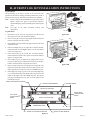
27020-3-0410 Page 19
FLAT FRONT LOG SET INSTALLATION INSTRUCTIONS
Log Installation
The positioning of the logs is critical to the safe and clean
operation of this heater. Sooting and other problems may result if
the logs are not properly and rmly positioned in the appliance.
Note: Before you begin: Do not handle these logs with your bare
hands! Always wear gloves to prevent skin irritation.
After handling logs, wash your hands gently with soap and
water.
Note: See Page 47 for Glass Assembly removal and
replacement.
Log Placement
1. Place Rear Log (A) onto rear log support. The notch in the
Rear Log ts over the rear Hot Surface Ignitor.
2. Place Left Log (B) on left rear log support shelf. The charred
portion of the log must face inward.
3. Place Middle Log (D) on front log support between the front
and back burners.
4. Place Front Right Log (F) on right side of Firebox bottom.
Notch in bottom of Front Right Log ts over the front Flame
sensor. See Figure 20A.
5. Place Front Left Log (E) on left side of Firebox bottom.
Notch in bottom of Front Left Log ts over front Hot Surface
Ignitor. See Figure 20B.
6. Place Right Log (C) on right rear log support shelf. Top of
log rests on Rear Log (A) and bottom of log rests on Firebox
bottom. Charred portion of log must face inward.
7. Place Left Top Long Log (G) on the pin on Left Log (B). The
upper left leg of Left Top Log will rest on Rear Log (A). The
upper right leg of Left Top Log will rest on Middle Log (D).
8. Place Right Top Long Log (H) on the pin on the Right Log
(C). The bottom left leg of the Right Top Log will rest in the
indent on the right side of the Middle Log (D). The bottom
right leg of the Right Top Log will rest in the indent in the
Front Right Log (F).
Figure 21
REAR LOG SUPPORT
FRONT LOG SUPPORT
FIREBOX BOTTOM
REAR HOT SURFACE IGNITOR
REAR FLAME SENSOR
REAR BURNER
RIGHT REAR
LOG SUPPORT
SHELF
FRONT BURNER
FRONT FLAME SENSOR
FRONT HOT SURFACE IGNITOR
LEFT REAR
LOG SUPPORT
SHELF
Figure 20B
B
F
D
A
H
C
G
E
Figure 20A

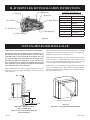
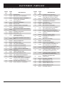
27020-3-0410Page 20
FLAT FRONT LOG SET INSTALLATION INSTRUCTIONS
LOG SET DIAGRAM - A
The Gas Log Kit contains the following:
Index Letter Log Description
A Rear Log
B Left Log
C Right Log
D Middle Log
E Front Left Log
F Front Right Log
G Left Top Log
H Right Top Log
A- Rear Log
B-Left Log
C-Right Log
D-Middle Log
E-Front Left Log
F-Front Right Log
G-Left Top Log
H-Right Top Log
Figure 22
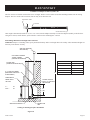
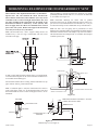
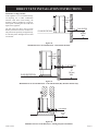
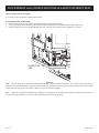
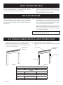
VENT EXAMPLES FOR SINGLE FLUE
Max Vent Run - 40 ft. Equivalent With Three (3) 90° Elbows
Special Note: The vent terminal 90° elbow and rst 90° el-
bowoffbackoftheheater,whenwithin6”(15.2cm),donot
contribute to the overall vent length measurement. For each
45° elbow installed in the horizontal run, the length of the
horizontal run MUST be reduced by 1.5 feet (45 cm). This
does not apply if the 45° elbows are installed on the vertical
partoftheventsystem.Reducethelengthofthehorizontal
run 3 feet (91.4 cm) for every 90° elbow.
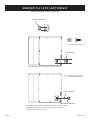
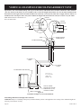
Note: On horizontal runs, a P.V.C. support clamp needs to be in-
stalled every 3 feet. No “sags” in horizontal vent runs; water will
settle in the pipe.
When installing a single ue horizontal, the minimum vent length
protruding from the outside wall is 6” (15.2 cm). See Figure 23.
Minimum vent from the rear of the unit is 12”.
Note: Horizontal discharge 90° elbow must be pointed down-
ward. See Figure 23. All horizontal runs require either a 1/4” per
foot rise to run condensation back to the heater, or a 1/4” per foot
downward slope to run condensation away from the heater.
Note: All PVC vent run piping can be purchased at a local hard-
ware store. Schedule 40 PVC pipe should be used and cemented.
Flex Kit and Horizontal Vent Adaptor Kit are available from Em-
pire Comfort Systems, Inc.
Figure 23
Single Flue - Straight Out Back
Min6”OutsideWall
Min 2” From Unit to Wall for Intake Air
Min vent length 12”
EXTERIOR GRADE
12” MIN.
6” MIN.
MIN. 2”
12” MIN.
SINGLE FLUE ADAPTOR
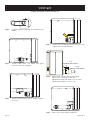
Figure 24
SingleFlue-VentingwithShroudKitInstalled
Page is loading ...
Page is loading ...
Page is loading ...
Page is loading ...
Page is loading ...
Page is loading ...
Page is loading ...
Page is loading ...
Page is loading ...
Page is loading ...
Page is loading ...
Page is loading ...
Page is loading ...
Page is loading ...
Page is loading ...
Page is loading ...
Page is loading ...
Page is loading ...
Page is loading ...
Page is loading ...
Page is loading ...
Page is loading ...
Page is loading ...
Page is loading ...
Page is loading ...
Page is loading ...
Page is loading ...
Page is loading ...
Page is loading ...
Page is loading ...
Page is loading ...
Page is loading ...
Page is loading ...
Page is loading ...
Page is loading ...
Page is loading ...
Page is loading ...
Page is loading ...
Page is loading ...
Page is loading ...
Page is loading ...
Page is loading ...
Page is loading ...
Page is loading ...
-
 1
1
-
 2
2
-
 3
3
-
 4
4
-
 5
5
-
 6
6
-
 7
7
-
 8
8
-
 9
9
-
 10
10
-
 11
11
-
 12
12
-
 13
13
-
 14
14
-
 15
15
-
 16
16
-
 17
17
-
 18
18
-
 19
19
-
 20
20
-
 21
21
-
 22
22
-
 23
23
-
 24
24
-
 25
25
-
 26
26
-
 27
27
-
 28
28
-
 29
29
-
 30
30
-
 31
31
-
 32
32
-
 33
33
-
 34
34
-
 35
35
-
 36
36
-
 37
37
-
 38
38
-
 39
39
-
 40
40
-
 41
41
-
 42
42
-
 43
43
-
 44
44
-
 45
45
-
 46
46
-
 47
47
-
 48
48
-
 49
49
-
 50
50
-
 51
51
-
 52
52
-
 53
53
-
 54
54
-
 55
55
-
 56
56
-
 57
57
-
 58
58
-
 59
59
-
 60
60
-
 61
61
-
 62
62
-
 63
63
-
 64
64


Ask a question and I''ll find the answer in the document
Finding information in a document is now easier with AI
Related papers
-
Empire Mantis FF28BM(N Owner's manual
-
-
-
-
-
-
-
-
-
Other documents
-
 Portals Plus 22035 Installation guide
-
SPT 10156 Installation guide
-
Montigo RFKFID User manual
-
-
Empire Heating Systems DV-35-2SG Owner's manual
-
 Cozy HEDV404 and User manual
-
Rheem Professional Classic Series: Direct Vent Co-Axial for Manufactured Housing User manual
-
-
Empire Comfort Systems PV-28SV55-(C,G)2H(N,P)-1 User manual
-

