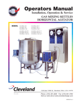
GAS CONTROL ASSEMBLY
ITEM ON. PART NO. DESCRIPTION QTY.
1. KE53441 BLOWER, 115V, 60 HZ . . . . . . . . . . . . . . . . . . . . . . . . . . . . . . . . . . . . . . . . . . . . . . . . . . . . . . . . . . . . . . . . . . . .1
KE53441-1 BLOWER, 220V, 50 HZ . . . . . . . . . . . . . . . . . . . . . . . . . . . . . . . . . . . . . . . . . . . . . . . . . . . . . . . . . . . . . . . . . . . .1
2. KE54420 AIR INTAKE WASHER (NATURAL GAS) . . . . . . . . . . . . . . . . . . . . . . . . . . . . . . . . . . . . . . . . . . . . . . . . . . . . . . .1
KE54420-1 AIR INTAKE WASHER (PROPANE) . . . . . . . . . . . . . . . . . . . . . . . . . . . . . . . . . . . . . . . . . . . . . . . . . . . . . . . . . . .1
3. KE54239 CAPACITOR . . . . . . . . . . . . . . . . . . . . . . . . . . . . . . . . . . . . . . . . . . . . . . . . . . . . . . . . . . . . . . . . . . . . . . . . . . . . .1
4. KE01426-4 MIXING CHAMBER, 40 GALLON KETTLES . . . . . . . . . . . . . . . . . . . . . . . . . . . . . . . . . . . . . . . . . . . . . . . . . . . .1
KE01426-1 MIXING CHAMBER, 60 GALLON KETTLES . . . . . . . . . . . . . . . . . . . . . . . . . . . . . . . . . . . . . . . . . . . . . . . . . . . .1
KE01426-2 MIXING CHAMBER, 80 GALLON KETTLES . . . . . . . . . . . . . . . . . . . . . . . . . . . . . . . . . . . . . . . . . . . . . . . . . . . .1
KE01426-3 MIXING CHAMBER, 100 GALLON KETTLES . . . . . . . . . . . . . . . . . . . . . . . . . . . . . . . . . . . . . . . . . . . . . . . . . . .1
5. KE53582 TUBING 1/4 INCH SILICONE . . . . . . . . . . . . . . . . . . . . . . . . . . . . . . . . . . . . . . . . . . . . . . . . . . . . . . . . . . . . . . .1
FI05156 HOSE FITTING . . . . . . . . . . . . . . . . . . . . . . . . . . . . . . . . . . . . . . . . . . . . . . . . . . . . . . . . . . . . . . . . . . . . . . . . . . .1
6. KE53402 AIR ORIFICE, 40 GALLON KETTLES . . . . . . . . . . . . . . . . . . . . . . . . . . . . . . . . . . . . . . . . . . . . . . . . . . . . . . . . .1
KE53402-1 AIR ORIFICE, 60 - 100 GALLON KETTLES . . . . . . . . . . . . . . . . . . . . . . . . . . . . . . . . . . . . . . . . . . . . . . . . . . . . .1
KE53402-2 AIR ORIFICE, 40 GALLON KETTLES (50 HZ BLOWER) . . . . . . . . . . . . . . . . . . . . . . . . . . . . . . . . . . . . . . . . . . .1
KE53402-3 AIR ORIFICE, 60 - 100 GALLON KETTLES (50 HZ BLOWER) . . . . . . . . . . . . . . . . . . . . . . . . . . . . . . . . . . . . . .1
7. KE01449 BLOWER MOUNTING PIPE ASSEMBLY . . . . . . . . . . . . . . . . . . . . . . . . . . . . . . . . . . . . . . . . . . . . . . . . . . . . . . .1
8. KE53618 SIGHT GLASS GASKET . . . . . . . . . . . . . . . . . . . . . . . . . . . . . . . . . . . . . . . . . . . . . . . . . . . . . . . . . . . . . . . . . . . .1
9. KE53617 SIGHT GLASS . . . . . . . . . . . . . . . . . . . . . . . . . . . . . . . . . . . . . . . . . . . . . . . . . . . . . . . . . . . . . . . . . . . . . . . . . . .1
10. KE53619 SIGHT GLASS RETAINER . . . . . . . . . . . . . . . . . . . . . . . . . . . . . . . . . . . . . . . . . . . . . . . . . . . . . . . . . . . . . . . . . .1
11. KE00515 THERMISTOR . . . . . . . . . . . . . . . . . . . . . . . . . . . . . . . . . . . . . . . . . . . . . . . . . . . . . . . . . . . . . . . . . . . . . . . . . . . .1
12. KE50556-2 WATER LEVEL PROBE . . . . . . . . . . . . . . . . . . . . . . . . . . . . . . . . . . . . . . . . . . . . . . . . . . . . . . . . . . . . . . . . . . . . .1
13. KE53437-3 IGNITOR . . . . . . . . . . . . . . . . . . . . . . . . . . . . . . . . . . . . . . . . . . . . . . . . . . . . . . . . . . . . . . . . . . . . . . . . . . . . . . . .1
14. KE53570 GASKET FOR IGNITOR . . . . . . . . . . . . . . . . . . . . . . . . . . . . . . . . . . . . . . . . . . . . . . . . . . . . . . . . . . . . . . . . . . . .1
15. FI05257 SHUT-OFF COCK . . . . . . . . . . . . . . . . . . . . . . . . . . . . . . . . . . . . . . . . . . . . . . . . . . . . . . . . . . . . . . . . . . . . . . . . .1
16. FI05213 PLUG . . . . . . . . . . . . . . . . . . . . . . . . . . . . . . . . . . . . . . . . . . . . . . . . . . . . . . . . . . . . . . . . . . . . . . . . . . . . . . . . . .1
17. KE53422 SPRING . . . . . . . . . . . . . . . . . . . . . . . . . . . . . . . . . . . . . . . . . . . . . . . . . . . . . . . . . . . . . . . . . . . . . . . . . . . . . . . .1
18. FA05002-4 “O” RING . . . . . . . . . . . . . . . . . . . . . . . . . . . . . . . . . . . . . . . . . . . . . . . . . . . . . . . . . . . . . . . . . . . . . . . . . . . . . . .1
19. GAS ORIFICES:
KE53403-8 NATURAL GAS - SEA LEVEL UP TO 2000', 40 GALLON KETTLES . . . . . . . . . . . . . . . . . . . . . . . . . . . . . . . . . .1
KE53403-5 PROPANE GAS - SEA LEVEL UP TO 2000', 40 GALLON KETTLES . . . . . . . . . . . . . . . . . . . . . . . . . . . . . . . . . .1
KE53403-6 NATURAL GAS - SEA LEVEL UP TO 2000', 60 - 100 GALLON KETTLES . . . . . . . . . . . . . . . . . . . . . . . . . . . . .1
KE53403-7 PROPANE GAS - SEA LEVEL UP TO 2000', 60 - 100 GALLON KETTLES . . . . . . . . . . . . . . . . . . . . . . . . . . . . .1
KE53403-8 NATURAL GAS - 2000' UP TO 4000', 40 GALLON KETTLES . . . . . . . . . . . . . . . . . . . . . . . . . . . . . . . . . . . . . . .1
KE53403-9 PROPANE GAS - 2000' UP TO 4000', 40 GALLON KETTLES . . . . . . . . . . . . . . . . . . . . . . . . . . . . . . . . . . . . . .1
KE53403-10 NATURAL GAS - 2000' UP TO 4000', 60 - 100 GALLON KETTLES . . . . . . . . . . . . . . . . . . . . . . . . . . . . . . . . . .1
KE53403-11 PROPANE GAS - 2000' TO 4000', 60 - 100 GALLON KETTLES . . . . . . . . . . . . . . . . . . . . . . . . . . . . . . . . . . . . .1
KE53403-12 NATURAL GAS - 4000' UP TO 6000', 40 GALLON KETTLES . . . . . . . . . . . . . . . . . . . . . . . . . . . . . . . . . . . . . . .1
KE53403-13 PROPANE GAS - 4000' UP TO 6000', 40 GALLON KETTLES . . . . . . . . . . . . . . . . . . . . . . . . . . . . . . . . . . . . . .1
KE53403-10 NATURAL GAS - 4000' UP TO 6000', 60 - 100 GALLON KETTLES . . . . . . . . . . . . . . . . . . . . . . . . . . . . . . . . . .1
KE53403-14 PROPANE GAS - 4000' UP TO 6000', 60 - 100 GALLON KETTLES . . . . . . . . . . . . . . . . . . . . . . . . . . . . . . . . . .1
20. FA05002-29 “O” RING . . . . . . . . . . . . . . . . . . . . . . . . . . . . . . . . . . . . . . . . . . . . . . . . . . . . . . . . . . . . . . . . . . . . . . . . . . . . . . .1
21. FI05226-4 NIPPLE, 1/2" NPT, 5 5/16" LONG . . . . . . . . . . . . . . . . . . . . . . . . . . . . . . . . . . . . . . . . . . . . . . . . . . . . . . . . . . . . .1
22. FI00073 UNION, 1/2" . . . . . . . . . . . . . . . . . . . . . . . . . . . . . . . . . . . . . . . . . . . . . . . . . . . . . . . . . . . . . . . . . . . . . . . . . . . . .1
23. FI00133 ELBOW, 1/2", STREET . . . . . . . . . . . . . . . . . . . . . . . . . . . . . . . . . . . . . . . . . . . . . . . . . . . . . . . . . . . . . . . . . . . . .1
24. KE93909 STRIP, TO HOLD BLOWER DOWN . . . . . . . . . . . . . . . . . . . . . . . . . . . . . . . . . . . . . . . . . . . . . . . . . . . . . . . . . . .1
25. FI00040-1 ELBOW, 1/2" . . . . . . . . . . . . . . . . . . . . . . . . . . . . . . . . . . . . . . . . . . . . . . . . . . . . . . . . . . . . . . . . . . . . . . . . . . . . .1
26. FI00579 NIPPLE, 1/2" NPT, 4" LONG, KGL-60-T . . . . . . . . . . . . . . . . . . . . . . . . . . . . . . . . . . . . . . . . . . . . . . . . . . . . . . . .1
FI05226-2 NIPPLE, 1/2" NPT, 4" LONG, KGL-80-T . . . . . . . . . . . . . . . . . . . . . . . . . . . . . . . . . . . . . . . . . . . . . . . . . . . . . . . .1
27. KE55004-3 RETAINING PLATE . . . . . . . . . . . . . . . . . . . . . . . . . . . . . . . . . . . . . . . . . . . . . . . . . . . . . . . . . . . . . . . . . . . . . . . .1
28. FI00573 NIPPLE, 1/2" NPT, 1 1/8" LONG . . . . . . . . . . . . . . . . . . . . . . . . . . . . . . . . . . . . . . . . . . . . . . . . . . . . . . . . . . . . . .1
29. FI05231 BUSHING, 3/4 - 1/2" NPT FLUSH, BLACK IRON . . . . . . . . . . . . . . . . . . . . . . . . . . . . . . . . . . . . . . . . . . . . . . . .1
30.
F01518-1 GAS SHUT-OFF VALVE, 3/4" (NOT FOR FRENCH CE KETTLES) . . . . . . . . . . . . . . . . . . . . . . . . . . . . . . . . . . . .1
31. FI05226 NIPPLE, 1/2" NPT, 8" LONG . . . . . . . . . . . . . . . . . . . . . . . . . . . . . . . . . . . . . . . . . . . . . . . . . . . . . . . . . . . . . . . . .1
32. FI05222 SWIVEL ELBOW . . . . . . . . . . . . . . . . . . . . . . . . . . . . . . . . . . . . . . . . . . . . . . . . . . . . . . . . . . . . . . . . . . . . . . . . . .1
33. FI05223 SPECIAL NIPPLE . . . . . . . . . . . . . . . . . . . . . . . . . . . . . . . . . . . . . . . . . . . . . . . . . . . . . . . . . . . . . . . . . . . . . . . . .1
34. KE02053 GAS VALVE ASSEMBLY . . . . . . . . . . . . . . . . . . . . . . . . . . . . . . . . . . . . . . . . . . . . . . . . . . . . . . . . . . . . . . . . . . . .1
35. KE53390 BRACKET FOR GAS VALVE . . . . . . . . . . . . . . . . . . . . . . . . . . . . . . . . . . . . . . . . . . . . . . . . . . . . . . . . . . . . . . . . .1
36. FI00607 NIPPLE, 3/4" NPT, 1 1/2" LONG . . . . . . . . . . . . . . . . . . . . . . . . . . . . . . . . . . . . . . . . . . . . . . . . . . . . . . . . . . . . . .1
37. KE01500-5 BURNER, 40 GALLON KETTLES, 140,000 BTU . . . . . . . . . . . . . . . . . . . . . . . . . . . . . . . . . . . . . . . . . . . . . . . . .1
KE01500-1 BURNER, 60-100 GALLON KETTLES, 190,000 BTU . . . . . . . . . . . . . . . . . . . . . . . . . . . . . . . . . . . . . . . . . . . . .1
38. KE53397 GASKET, BURNER . . . . . . . . . . . . . . . . . . . . . . . . . . . . . . . . . . . . . . . . . . . . . . . . . . . . . . . . . . . . . . . . . . . . . . . .1
39. FI05231 ADAPTOR . . . . . . . . . . . . . . . . . . . . . . . . . . . . . . . . . . . . . . . . . . . . . . . . . . . . . . . . . . . . . . . . . . . . . . . . . . . . . .1
40. KE601085 COVER FOR GAS VALVE . . . . . . . . . . . . . . . . . . . . . . . . . . . . . . . . . . . . . . . . . . . . . . . . . . . . . . . . . . . . . . . . . . .1
41. RB018151 GASKET FOR COVER . . . . . . . . . . . . . . . . . . . . . . . . . . . . . . . . . . . . . . . . . . . . . . . . . . . . . . . . . . . . . . . . . . . . .1
42. KE601081 BRACKET . . . . . . . . . . . . . . . . . . . . . . . . . . . . . . . . . . . . . . . . . . . . . . . . . . . . . . . . . . . . . . . . . . . . . . . . . . . . . . .1