Page is loading ...

EZ-USB Series 2100 Family
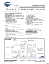
The Anchor Chips EZ-USB™ family (AN21XX/AN23XX) provides
significant improvements over other USB architectures including an
enhanced 8051 core, 4 or 8 Kbytes of RAM, an intelligent USB core, and
high-performance I/O ports. The family includes 16 different products to
accommodate the needs of different systems.
The enhanced 8051 core provides five times the performance of the
standard 8051, while maintaining complete 8051 software compatibil-
ity. With on-chip RAM, firmware code can be downloaded from the
host PC. This allows the peripheral manufacturer to easily modify and
transfer new code to current and new users. This on-chip memory
eliminates the need for external memory.
The EZ-USB family supports high-bandwidth transfers by providing
an efficient mechanism to move data between external memory and
the USB FIFOs. Using this “turbo mode,” the 8051 core can transfer
1024 bytes of data in or out of an isochronous FIFO in 338 microsec-
onds. This leaves a high percentage of the bandwidth for the processor
to service the application. The EZ-USB family also supports an equiva-
lent data transfer rate for bulk packets of over 2 Mbytes per second,
which is more than the USB bandwidth.
The EZ-USB family conforms to the high-speed (12 Mbps) require-
ments of USB Specification version 1.0, including support for remote
wake-up. The internal SRAM replaces Flash memory, EEPROM,
EPROM, or masked ROM that is conventionally used in other USB
solutions.
The EZ-USB family offers two packages, a 44 PQFP and an 80 PQFP.
All EZ-USB devices are pin- and software-compatible. And, all RAM
versions have ROM equivalents to allow easy migration for high-
volume applications.
Features
·
Single-chip, low-power
solution for high-speed USB
peripherals
· Firmware downloadable
· High-performance I/O port
· Small board space (less than
1 square inch)
· 44 PQFP or 80 PQFP
· USB Specification 1.1
compliant
· Uses commercially-available
8051 software tools
· Thirty-one flexible endpoints
· All endpoints can be double
buffered
· 4 or 8 Kbytes of memory
· Five times the speed of a
standard 8051
· Supports composite devices
· I²C controller
· Supports isochronous, bulk,
control, and interrupt data
· On-chip PLL
EZ-USB Series 2100
AN2121SC AN2321SC
AN2125SC AN2325SC
AN2126SC AN2326SC
AN2131SC AN2331SC
AN2135SC AN2335SC
AN2136SC AN2336SC
AN2131QC AN2331QC
EZ-USB™ Series 2100
USB Controller

EZ-USB Series 2100
High-Speed
Peripheral
Shared
Memory
Flash ROM
EEPROM
EPROM
ROM
Micro-
processor
DMS
Controller
(Optional)
USB
Protocol
Controller
Chip
USB
Port
I/O
The EZ-USB RAM
architecture provides
design and software
flexibility. Its “soft” configuration
enables peripheral manufacturers
and designers to make changes to
the USB device through software.
This means complete flexibility
with minimal design risks.
The EZ-USB family uses
an intelligent USB core to
simplify 8051 firmware
code by as much as 80%. This
reduces the firmware designer’s
need to develop code to handle
the low-level nuances of the USB
specification. The designer is free
to concentrate on higher level
functions. EZ-USB firmware
development is quick, requiring
less binary code and reducing the
likelihood of errors.
With the EZ-USB family’s
software utilities and
tools, firmware develop-
ment is simplified and accelerated.
Firmware can be tested indepen-
dent of drivers, allowing the
firmware developer and driver
software developer to write code
simultaneously. They do not need
each other to verify and test code.
This dual path decreases software
development time.
Anchor Chips’ EZ-USB family
eliminates the need to become an
expert in USB. It allows the
designer to take advantage of the
benefits of USB without investing
large amounts of time and
energy. With the EZ-USB family,
peripheral designers can have
USB traffic running within
hours, instead of weeks as with
other USB solutions.
The EZ-USB family of controllers
simplifies the process of imple-
menting USB hardware and
software development for
peripheral manufacturers. Low-
level USB protocol requirements
are automatically handled by the
Anchor smart USB core and the
included software utilities.
A typical USB
implementation uses
nonvolatile memory
(EPROM, EEPROM, Flash memo-
ry), a microprocessor, RAM, USB
SIE and DMA. The EZ-USB
family includes all the building
blocks for a complete and low-
cost USB solution in a single chip.
The design is much simpler since
timing and interface analysis are
significantly reduced.
4
3
2
1
Complete USB Design Made Easy
With the EZ-USB family, the
peripheral designer gains
two overall advantages:
First, the design is much
simpler because of the
chip’s significant
integration and built-in
flexibility. Second, the
EZ-USB architecture
reduces software code
significantly over other USB
solutions. This combination
gives users a quick and easy
path toward obtaining a
working prototype.
Typical USB
Implementation
Anchor USB
Solution
How does Anchor Chips
make USB easy?

EZ-USB Series 2100
Single-Chip Solution
Lower overall system cost
Minimum board space with 44 PQFP and 80 PQFP packages
Quicker design and faster time to market than other USB solutions
Minimal design resources
RAM Architecture
Quick changes in firmware and driver code
Updates in the field via software downloads
Flexibility in multiple configurations
Dynamic changes in performance/properties based on user’s needs
High-Performance I/O
Transfers a full 1024-byte isochronous packet within one USB frame
Provides highest quality full-motion video or audio performance
Data I/O rate greater than 2 Mbyte/sec for bulk and isochronous packets
Fastest response time for the end user
4- or 8-Kbyte
Easy transition from RAM to ROM for high-volume applications
Pin- and Software-
Pin- and software-compatible options for program code growth
Compatible Family
No change in hardware as needs change
Lowers system cost since only minimal memory size is needed
EZ-USB Firmware
Significantly less 8051 USB code since core handles most USB activity
Architecture
Shortened USB learning curve
Quicker working prototypes and final production models
More software development time to devote to the peripheral function
Enhanced 8051 Core
Five times faster performance than 8051
No new 8051 software tools to learn
Anchor USB Core/
External EPROM components eliminated
ReNumeration
A quick path to working prototypes
Capability
User-selectable changes in peripheral properties without disconnecting
EZ-USB Xcelerator
Speedier firmware and driver development
Development Kit
Independent development of firmware and driver
Fewer software errors
No custom Windows
®
driver needed to test USB traffic and firmware
Low 3.3V Power
Meets the 100 mA power-up specification
Useful in bus-powered applications
Useful in power-sensitive applications such as battery-powered equipment
Five External Interrupts
Flexible without sacrificing standard 8051 interrupts
Separate Memory
Design flexibility in USB program code
Expansion Port
No sacrifice in I/O capability for high-functionality peripheral devices
Non-multiplexed, requiring no external latch
Features Benefits

EZ-USB Series 2100
The focus of the EZ-USB
family is to provide the
peripheral designer a
multitude of design
configurations and
migration paths. The “soft,”
programmable nature of the
EZ-USB architecture
provides flexibility while
minimizing risks.
USB requires synchronization
between four major technology
suppliers: operating system,
UHCI/OHCI interfaces, hub
controllers, and peripheral
devices. In a traditional hard-
ware configuration, ensuring
that a peripheral device will
work with every combination of
these technologies is a time-
consuming and expensive task.
Using the EZ-USB chip’s “soft”
configuration, the peripheral
developer can easily devise
workarounds or accommodate
dynamic changes. At the same
time, there is minimum risk to
design implementation.
Peripheral manufacturers can
provide firmware updates in
conjunction with driver changes
via a floppy disk or through
Internet downloads. Thus,
Unprecedented “Soft” Architecture
software device configurability
provides easy field updates, last
minute software code changes
prior to production, or alterations
due to ever-changing standards.
In these ways, the EZ-USB chip
makes development easier and
guards against product obsoles-
cence.
RAM Architecture
With an enhanced 8051 core
combined with 4 or 8 Kbytes of
SRAM in a single chip, users have a
complete solution. The 8051’s
firmware can be stored in the hard
disk (along with the driver) and
downloaded into the peripheral
during its initialization. That
makes updates as easy as updating
any other PC software.
Host PC
Soft Configuration
Code
Download
RAM
Anchor Chips
USB Controller
Now it’s easy.
Hardware configuration
Software upgrades
Memory enhancements
Feature upgrades
¤
¤
¤
¤

EZ-USB Series 2100
Enumeration and
ReNumeration
Anchor Chips’ proprietary
ReNumeration™ function is the
means by which the enhanced
8051 firmware is downloaded.
How It Works
Upon power-up or plug-in, the
EZ-USB chip automatically
enumerates as a default USB
device. This allows the USB core
to download 8051 code. The USB
core logic inside EZ-USB per-
forms this initial enumeration
and code download while holding
the 8051 in reset.
Once enumerated, the host PC
downloads 8051 code into
EZ-USB RAM over the USB
interface. (Anchor Chips supplies
the software tools to incorporate
the loader into any application).
The downloaded 8051 code
contains program, data, and
enumeration tables. Once loaded,
the EZ-USB core performs a
ReNumeration cycle to simulate a
USB disconnect and reconnect to
come back as a completely new
USB device.
This entire sequence of enumera-
tion, download and ReNum-
eration happens quickly (less
than a quarter of a second) and is
transparent to the user.

EZ-USB Series 2100
USB firmware develop-
ment is faster since there
is less code to write. This
reduction in firmware allows the
design team to concentrate more
on software development for the
peripheral function.
Fewer 8051 MIPs are
dedicated to USB
processing. With the
EZ-USB family, as little as 10% of
8051 processing time is dedicated
to USB. That makes 90% of the
enhanced 8051 core’s processing
time available for peripheral
functions. Alternate solutions
dedicate more of their micro-
controller bandwidth to USB
processing.
The EZ-USB family
handles most low-level
USB overhead automati-
cally. Therefore, the learning
curve to understand all the
nuances of USB is reduced,
yielding fewer code errors and
faster product development.
Four Major Benefits of
Smart USB Core
The firmware code is
smaller and more
efficient than alternate
USB solutions. In the EZ-USB
family, the memory requirement
is reduced by a factor of two to
five times as compared to other
solutions. And, since less memory
is needed for firmware, board
size and system cost are reduced.
Automatically Handles Low-Level USB Overhead
Test Code Supports:
· USB Chapter 9
· String descriptors
· USB suspend/resume
· Remote wake-up
· Bulk endpoint loopback
4
2
A USB hardware connection
is simpler than current
interface standards (ISA,
PCI, serial, parallel, and
SCSI). For example, there
are no IRQs or DMAs to set.
USB does not use direct
connections like RS232 or
EPP (Enhanced Parallel
Port). Instead, USB is a
packetized protocol similar
to telecommunication
standards such as X.25 or
frame relay. This makes
software development
complex.
3
The EZ-USB chip family reduces
the complexity of USB. It has a
predefined default descriptor
that causes it to function as a
generic USB device. Very little
code is required to operate the
EZ-USB chip when configured in
this default state. The default
descriptor can be replaced as the
peripheral manufacturer devel-
ops customized firmware.
Efficient EZ-USB Code
1
Firmware
File Type
EZ-USB Family Alternate Solutions
Source 730 lines of C code 5445 lines of assembly code
Binary < 1 Kbyte > 5 Kbytes

EZ-USB Series 2100
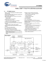
This diagram shows how conventional USB controllers handle a three-stage USB setup transaction called “Get
Descriptor.” The serial data flowing over the USB is shown as three stages: Setup, Data and Status. The
numbered arrows indicate transfers between the USB, endpoint FIFOs, and microprocessor memory. Significant
CPU overhead is required to transfer the data to and from the endpoint FIFOs (2,3,5) and to divide the
descriptor table data into packets for transmission using multiple USB data packets (4,6).
The EZ-USB core directly transfers setup packet data into a dedicated eight-byte Setup data buffer for CPU
inspection (1). Then the 8051 loads an EZ-USB pointer with the start address of the requested descriptor data
(2). The EZ-USB core does the rest. The EZ-USB core automatically takes care of error checking and retries,
dividing the table into packets for the various IN transfers and responding to the Status stage.
Comparison of Standard USB Request “Get Descriptor”
Conventional Method
1 USB Setup data copied to
FIFO
2 CPU copies FIFO data to
RAM; decodes Get Descriptor
request
3 CPU transfers first packet of
data from memory to endpoint
FIFO
4 FIFO data sent in response to
USB IN token
5 CPU transfers next packet of
data from memory to endpoint
FIFO
6 FIFO data sent in response to
USB IN token
7 Repeat steps 5-6
EZ-USB Method
1 EZ-USB core copies Setup
data directly to RAM,
eliminating the FIFO-to-RAM
copy step. The 8051
decodes the Get Descriptor
request.
2 The 8051 sets pointer to
descriptor table in RAM.
EZ-USB core does entire
multi-packet transfer.

EZ-USB Series 2100
Turbo Performance
To make full use of the USB
bandwidth, the EZ-USB family
has large endpoint buffers and a
fast method for transferring data
into and out of the buffers. With
the EZ-USB architecture, bulk
and isochronous endpoints can
be configured as double-buffered
with maximum packet sizes.
With the 2-Kbyte FIFO, the
EZ-USB family can transfer a
1024-byte isochronous packet
within a single USB frame.
Similarly for bulk endpoints, the
EZ-USB can transfer data using
the 64-byte double buffer capa-
bilities at a data transfer rate of
greater than 2 Mbytes per
second.
Fast transfer rates can occur in
and out of the internal FIFOs to
external peripherals since the
EZ-USB core automatically
monitors 8051 transfers between
the accumulator and the end-
point FIFO registers. When one of
these transfers occurs, the
EZ-USB core also reads or writes
the FIFO data over the external
data bus and provides external
FIFO read and write strobes for
the external interface.
Turbo Isochronous
Capability
The EZ-USB family provides
1024 bytes of double-buffered
FIFO memory (2048 bytes in all)
which may be divided between
16 isochronous endpoints.
During any one millisecond
frame time, one of the FIFOs is
connected to the USB and the
other to the 8051. At every SOF
(Start Of Frame), the buffers
“ping-pong” so the 8051 can
access the last frame’s data while
the other FIFO empties or fills
with new USB data.
A single “movx” instruction
transfers data between EZ-USB
endpoint FIFOs and external logic
in two cycles or 330 nano seconds.
Based on these connections a
complete 1024-byte transfer can
take 388 microseconds, less than
40% of the 1 ms USB frame time.
This is an equivalent transfer rate
of greater than 2 Mbytes per
second.
Turbo Bulk Capability
USB bulk endpoint data is avail-
able to the 8051 as 16 64-byte
buffers in RAM. A special bulk
data pointer allows this RAM data
to also be accessed as a FIFO. The
8051 loads this sixteen-bit pointer
with the address of a bulk buffer.
Then, using a special data register,
accesses the buffer data as if it
were a FIFO. Every read or write
to the data register increments the
address pointer. This gives the
8051 a third data pointer: one that
auto-increments.
As with the fast isochronous
mode, the special data register
uses the turbo mode that allows a
byte of data to be transferred
using a single “movx” instruction.
Bulk transfers in and out of the
8051 therefore can be done with
the speed of the isochronous
transfers, one byte every two
cycles (330 nanoseconds). This
performance can generate well
over the maximum allowable bulk
packets within a USB frame.
The EZ-USB family
provides the maximum
performance specified for
USB. This allows the
peripheral manufacturer to
take advantage of USB’s
full bandwidth in high-
speed applications such as
full-motion video,
continuous audio, scanning,
digital photography, and
printing.

EZ-USB Series 2100
To write data to outside logic, the 8051 loads a data pointer with a USB FIFO register address, and then executes a “movx
a,@dptr” instruction to move a byte from the FIFO to the 8051 accumulator. The EZ-USB core simultaneously broadcasts the FIFO
data on the external data bus pins and generates the external write signal FWR# (Fast Write). A 24 MHz clock is provided for use
as an external FIFO clock, if required. EZ-USB control bits allow the timing and polarity of the FWR# signal to be tailored for
different external interface requirements.
To read data from outside logic, the 8051 loads a data pointer with a USB FIFO register address, and then executes a “movx
@dptr,a” instruction to move a byte from the accumulator to the FIFO. The EZ-USB core discards the accumulator data and instead
writes a byte from the external data bus pins to the FIFO. The EZ-USB core provides the external read signal FRD# (Fast Read) to
strobe the data, and a 24 MHz clock. Like the FRW# signal, the FRD# signal may be tailored for different interface requirements.
support extra features such as a
second data pointer, a second
UART, cycle-stretched timing, an
expanded interrupt system, and
enhanced timers.
instructions on bits, flags, and
other status functions are identi-
cal to the standard 8051. The
enhanced 8051 core also provides
special function registers that
The enhanced 8051 processor
increases performance by
executing most instructions in
four clock cycles instead of
twelve, as in the standard 8051.
The enhanced 8051 core also
runs at 24 MHz; that’s twice as
fast as the standard part. These
factors improve the execution
rate for most instructions by a
factor of five. The enhanced
8051 core contained in the
EZ-USB family is binary-code
compatible and performs the
same functions as the industry-
standard 8051. The effects of
A Leap in Performance with 8051 Compatibility
Clocks per instruction cycle 12 4
Data pointers 1 2
Serial ports (UARTs) 1 2
16-bit timers 1 3
Interrupt sources (int and ext) 5 13
Stretch memory cycles No Yes
Nominal operating frequency 12 MHz 24 MHz
Nominal operating voltage 5 V 3.3 V
Feature Standard Anchor

EZ-USB Series 2100
Flexible for Many Applications
Loading 8051 Firmware from the Host
Options for Loading
8051 Firmware
The EZ-USB family provides
the peripheral developer with
four options for loading its
8051 firmware.
Software file from the
host system
Loading from a software file
provides the maximum flex-
ibility to the peripheral manu-
facturer. This configuration
takes advantage of the internal
4K or 8K RAM to load 8051 code
and data from the host system.
Because of the ReNumeration
capability of EZ-USB chips, a
new set of descriptors can be
loaded after the initial enumera-
tion without physically discon-
necting the device. This allows
device descriptors and 8051
program code to be loaded from
a driver disk. Only the vendor
ID, product ID, and device ID
need to be loaded during boot
time in hardware through a 16-
byte EEPROM. Using this
EEPROM loaded through the
I
2
C port
The EZ-USB architecture supports
an external EEPROM load
through the I
2
C bus. This gives
designers the capability to load
8051 program code from hard-
ware. Because of the flexibility of
the external EEPROM and inter-
nal RAM, manufacturers have the
option to make last-minute
changes to a design/code without
impacting production schedules.
External memory through the
memory expansion port
External memory may be added to
EZ-USB family members in the
80-pin PQFP package. This
memory is available through a
memory expansion port. Separate
16-bit address and 8-bit data
busses are also available to
directly attach to a 64K EPROM,
SRAM, or Flash memory. Unlike a
standard 8051, the address and
memory ports are not multi-
plexed, eliminating the need for
glue logic for connection to
external memory.
Internal ROM for peripheral
manufacturers who migrate to the
ROM-based EZ-USB chip
EZ-USB ROM options are soft-
ware and pin compatible to RAM
members of the family. Therefore,
high-volume customers can move
easily to ROM when their 8051
firmware code is solidified.
The EZ-USB architecture
includes features that give
the designer many options
for creating an efficient and
effective design that is
tailored to the needs of an
application.
configuration, users can implement
a USB function in a tiny 44 PQFP
package yielding a complete USB
solution in less than one square
inch of PC board space.

EZ-USB Series 2100
More Endpoint Buffer
Memory
The EZ-USB chip supports more
endpoints and provides more
endpoint buffer memory than any
other USB-device solution in the
market. The USB specification
describes an endpoint as a source
or sink of data. In the EZ-USB
chip, endpoints are constructed
as RAM (bulk, control, interrupt
endpoints) or FIFOs (isochronous
endpoints). With support for 31
endpoints (the maximum in the
USB specification), it gives the
peripheral designer ultimate
flexibility. Unlike other USB
peripheral alternatives, the
EZ-USB architecture also sup-
ports the maximum packet size
for each endpoint. Thus 64-byte
packets are available for all
control, bulk, and interrupt
endpoints. Isochronous endpoints
are double buffered with a packet
size of up to 1024 bytes, the
maximum allowable under the
USB specification.
Control
The EZ-USB family supports one
control endpoint. To simplify
firmware programming, the
EZ-USB chip provides data from
control transfers in two separate
buffers. It also has a unique
capability to manage the three-
phase transfer in hardware,
relieving device firmware from
this task.
Bulk/Interrupt
Bulk endpoints are used when
data integrity must be guaran-
teed, but without critical delivery
time. The EZ-USB family provides
14 bulk endpoints: seven IN and
seven OUT. These endpoints can
be programmed to be double-
buffered, which improves trans-
fer bandwidth in some applica-
tions. Bulk data is accessible as
RAM or FIFO data. The IN and
OUT endpoints can also be used
as interrupt endpoints.
Isochronous
These endpoints support stream-
ing data such as audio or video.
The EZ-USB family supports 16
isochronous endpoints: eight IN
and eight OUT. A pool of FIFOs
can be allocated among the
endpoint to a maximum of
1 Kbyte. Isochronous endpoints
are double-buffered, as required
by the USB specification, so the
actual size of iscochronous buffer
memory is 2 Kbytes.
Low Power—Even for
Bus-Powered Devices
The EZ-USB family meets the
tough power specifications of
USB. Running off of a 3.3V power
supply, it can accommodate bus-
powered devices and self-pow-
ered peripherals. In addition,
with a 50 mA current draw under
full operating conditions, the
EZ-USB family provides current
headroom for peripheral func-
tions. This meets the USB require-
ment of 100 mA maximum
current for attached peripherals
prior to configuration. Total
maximum power required by an
EZ-USB chip under active condi-
tions is 170 mW. Other solutions
require five times more power.
Thirty-one
Endpoints
for Ultimate
Flexibility

EZ-USB Series 2100
EZ-USB Series 2100 Xcelerator Development Kit
Development Board
The EZ-USB Xcelerator develop-
ment board is compact and
powerful. It provides an
AN2131QC, 64 kilobytes of
external RAM, two UARTS, and
user-programmable seven
segment display, LED indicators,
and switches. One UART is used
to communicate with the Win-
dows-hosted debugger, and the
other is free for application use.
The indicators and switches are
connected via the EZ-USB I
2
C
port, leaving all AN2131QC I/O
lines uncommitted for prototype
development. The board can be
USB bus powered, eliminating
the need for an external power
supply. A debug monitor loads
either into internal EZ-USB RAM
or the external RAM. The exter-
nal RAM can be configured in
various ways to allow seamless
code development for EZ-USB
ROM versions.
A matching plug-in breadboard
eases the interface of custom
circuitry to the AN2131. Headers
bring out all interface signals, and
provide a convenient interface to
a logic analyzer.
C Compiler from Keil
The C compiler from Keil Soft-
ware lets the designer write 8051
microcontroller applications in C
and still get the efficiency and
speed of assembly language.
Advanced features from Keil tools
include the ability to single step
through code. This makes it easy
to detect errors, handle source
level debugging and dual-data
pointer support, and set
breakpoints. With the ability to
debug code one line at a time,
quickly compile and one-step
download new code, developers’
have a more efficient means to
complete firmware faster than
using emulators.
The EZ-USB Xcelerator™
development kit provides a
complete hardware and
software solution for
accelerating the firmware
and device driver
development for all the
members of the EZ-USB
family. Other USB
development kits use
emulation of the eventual
USB device. The EZ-USB
Xcelerator developer kit uses
the actual device, the
AN2131QC, during the
entire development. Because
of the simplicity of EZ-USB
and Anchor’s software
utilities, users can be up and
running USB code in hours,
not weeks!

EZ-USB Series 2100
Anchor Utilities
Anchor Chips provides the best
tools to accelerate the developer’s
firmware development. The USB
Control Panel allows the developer
to send and receive interrupt, bulk,
and isochronous packets and
standard USB device requests
without first developing the host-
based driver for the specific
application. The USB Control
Panel provides manual control of
USB host controller response. It can
be used to test a multitude of
operating conditions without first
learning low-level USB program-
ming. The user can quickly test
different packet sizes and emulate
USB host application responses. In
addition, users can quickly test
and adjust firmware based on
immediate results from the USB
Control Panel.
Also in the EZ-USB development
kit is the EZ-USB 8051 firmware
library and firmware frame-
works. With this library of
predefined function calls, devel-
opers can quickly develop their
peripheral function. The firm-
ware library includes functions
such as ReNumeration, I
2
C
programming, descriptor table
parsing, USB initialization, device
initialization, suspend/resume
and complete USB standard
device request processing.
Device Driver
A general-purpose device driver
is included in the Xcelerator
development kit. It is a WDM
driver for Windows 98 or OSR
2.1. With source code provided,
peripheral driver developers can
convert this code to a miniport
driver to meet their unique needs.
· EZ-USB Development Board
· EZ-USB Peripheral Board
· EZ-USB Firmware Library and Firmware Frameworks
· EZ-USB General-Purpose Device Driver
· EZ-USB Driver and Firmware Sample Code
· EZ-USB Control Panel
· EZ-USB Documentation
· Reference Schematics
· 8051 C Compiler from Keil Software
· 8051 Assembler from Keil Software
· 8051 Custom Debugger from Keil Software
The EZ-USB Series 2100
Xcelerator Development Kit
(AN2131-DK-001)

EZ-USB Series 2100
3.0
3.0
80 PQFP
0.80
1.00 Ref
124
25
40
64
41
80
65
0.80 BSC.
24.10
23.70
20.05
19.95
18.10
17.70
14.05
13.95
Packages and Pin Definitions
1
10.10
9.90
13.45
12.95
8.00 REF
11
33
23
12 22
44 34
0.80 BSC.
44 PQFP
2.35 MAX
0.45
0.30
0
o
~7
o
1.00
0.80
1.95 + 0.15
80-Pin Lead Detail
2.76
2.66
0.28
0.18
8 Places
12
o
REF.
Base Plane
Seating Plane
0
o
~10
o
0.25 Gage Plane
3.04 MAX
0.42
0.32
0
o
~7
o
0.95
0.65
1.60 TYP
44-Pin Lead Detail
2.10
1.95
0.25
0.10
0.23
0.13

EZ-USB Series 2100
tuptuO/tupnItuptuO/tupnI
tuptuO/tupnI
tuptuO/tupnItuptuO/tupnI
CS5212CS5212
CS5212
CS5212CS5212
CS6212
CS5312
CS6312
CS1212CS1212
CS1212
CS1212CS1212
CS1312
CQ1312CQ1312
CQ1312
CQ1312CQ1312
emaNemaN
emaN
emaNemaN
86tuo0T/0AP
96tuo1T/1AP
07#EO/2AP
17#SC/3AP
939337#RWF/4AP
040447#DRF/5AP
57tuo0DxR/6AP
67tuo1DxR/7AP
42442T/0BP
5254XE2T/1BP
62641DxR/2BP
72741DxT/3BP
82254TNI/4BP
9235#5TNI/5BP
03456TNI/6BP
1355tuo2T/7BP
4141030DxR/0CP
5151130DxT/1CP
616123#0TNI/2CP
717133#1TNI/3CP
8181830T/4CP
9191931T/5CP
020204#RW/6CP
121214#DR/7CP
dnuorGdnarewoPdnuorGdnarewoP
dnuorGdnarewoP
dnuorGdnarewoPdnuorGdnarewoP
77 81DNGA
010112CCVA
,5,4,3,1
,32,21,6
83,43
,5,4,3,1
,32,21,6
83,43
,31,6,5,3
,32,71,41
,36,65,34
87,27
DNG
,22,11
44,33
,22,11
44,33
,22,2
26,24
CCV
sserddAsserddA
sserddA
sserddAsserddA
CS5212CS5212
CS5212
CS5212CS5212
CS6212
CS5312
CS6312
CS1212CS1212
CS1212
CS1212CS1212
CS1312
CQ1312CQ1312
CQ1312
CQ1312CQ1312
emaNemaN
emaN
emaNemaN
21-75A-0A
61,517A,6A
92-6211A-8A
73-4351A-21A
subataDsubataD
subataD
subataDsubataD
72-4215-843D-OD
13-8206-757D-4D
laicepSlaicepS
laicepS
laicepSlaicepS
232316TPKB
224 42KLC
34341 #NOCSID
08#NESP
88 91NIX
99 02TUOX
42AE
313152TESER
737366#PUEKAW
O/IBSUO/IBSU
O/IBSU
O/IBSUO/IBSU
141477-DBSU
242497+DBSU
II
I
II
22
2
22
CC
C
CC
636356LCS
535346ADS

EZ-USB Internal ROM Product Family
EZ-USB Internal RAM Product Family
Ordering Information
With the broadest family of USB solutions in the market, peripheral manufactures can find the right
combination of features, board space, and price to fit their applications. All eight of EZ-USB family
members with internal RAM can be converted to ROM equivalents with no changes in their design.
EZ-USB Xcelerator Development Kit AN2131-DK-001
EZ-USB, Xcelerator, and ReNumeration are trademarks of Anchor Chips Incorporated. The Anchor logo is a registered trademark of Anchor Chips Incorporated. Cypress and the
Cypress logo are trademarks of Cypress Semiconductor. All other tradesmark are the property of their respective owners. Specifications are subject to change without notice. © 1999,
Anchor Chips Incorporated All rights reserved. 2-799EZ21K
Cypress Semiconductor
3901 North First Street • San Jose, CA 95134
Telephone (800) 858-1810 • Fax (408) 943-6848
www.cypress.com
Anchor Chips Incorporated
12396 World Trade Drive • M/S 212 • San Diego, CA 92128
Telephone (858) 613-7900 • Fax (858) 676-6896
www.anchorchips.com
A Business Unit of Cypress Semiconductor
For more information about the EZ-USB controller chip, visit www.anchorchips.com.
Part Package RAM I/O Rate # Prog 8-Bit Isochronous
Number Type Size Bytes/sec I/Os Databus Support
AN2121SC 44 PQFP 4K 600K 16 No Yes
AN2125SC 44 PQFP 4K 2M 8 Yes Yes
AN2126SC 44 PQFP 4K 2M 8 Yes No
AN2131SC 44 PQFP 8K 600K 16 No Yes
AN2135SC 44 PQFP 8K 2M 8 Yes Yes
AN2136SC 44 PQFP 8K 2M 8 Yes No
AN2131QC 80 PQFP 8K 2M 24 Yes+Addr Yes
Part Package RAM ROM I/O Rate # Prog 8-Bit Isochronous
Number Type Size Size Bytes/sec I/Os Databus Support
AN2321SC 44 PQFP 2K 4K 600K 16 No Yes
AN2325SC 44 PQFP 2K 4K 2M 8 Yes Yes
AN2326SC 44 PQFP 2K 4K 2M 8 Yes No
AN2331SC 44 PQFP 2K 8K 600K 16 No Yes
AN2335SC 44 PQFP 2K 8K 2M 8 Yes Yes
AN2336SC 44 PQFP 2K 8K 2M 8 Yes No
AN2331QC 80 PQFP 2K 8K 2M 24 Yes+Addr Yes
"C" denotes commercial (0 - 70 degrees C) temperature range
All EZ-USB devices support up to 14 endpoints for bulk packets.
/