
Stockton 8
Integral Boiler Stove
MODEL: 7129
Installation and Operating
Instructions
F
or Use in Great Britain and Eire
IMPORTANT
Please read these instructions carefully before using the appliance.
Keep them safe for future reference and when servicing the stove.
PM140-Issue 1 (April 2005)
This product is suitable for use in the stated countries. To install the product in other countries it is essential to obtain translated instructions
and in some cases the product may require modification. Contact Stovax to obtain further information.

2
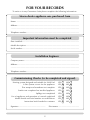
FOR YOUR RECORDS
To assist us in any Guarantee claim please complete the following information:-
Stovax dealer appliance was purchased from
Name: ......................................................................................................................
Address:....................................................................................................................
.................................................................................................................................
Telephone number:...................................................................................................
Important information must be completed
Date installed:...........................................................................................................
Model description:....................................................................................................
Serial number: ..........................................................................................................
Installation Engineer
Company name: .......................................................................................................
Address:....................................................................................................................
.................................................................................................................................
Telephone number:...................................................................................................
Commissioning Checks (to be completed and signed)
Heating system designed and suitable for Solid Fuel YES NO
Is flue system correct for the appliance YES NO
Flue swept and soundness test complete YES NO
Smoke test completed on installed appliance YES NO
Spillage test completed YES NO
Use of appliance and operation of controls explained YES NO
Model details and serial number recorded above YES NO
Instruction book handed to customer YES NO
Signature: .................................................. Print name:.......................................

3
PRE-INSTALLATION CHECKS
Before installation of this product please read these instructions fully.
It is very important to also understand the requirements of the UK Building Regulations
(England and Wales – Document J / Scotland - Part F), along with any local regulations that
may apply. Should any conflict occur between these instructions and these regulations the
regulations shall apply.
Your local Building Control Officer would be happy to advise should questions arise regarding
the requirements of the regulations.
The Stockton stove should be fitted by a HETAS approved installer, or approved by your local
Building Control Officer. Your Stovax dealer should be able to arrange this service for you.
A faulty installation could cause danger to the inhabitants and structure of the building.
All heating systems should be designed by a competent heating engineer, and be suitable
for a Solid Fuel appliance.
1. FLUE AND CHIMNEY
The construction of the Flue or Chimney system should meet the requirements of the Building
Regulations.
The minimum flue sizes required are:-
Stockton 8 150mm (6”) diameter or 135 (5
1
/
2
”) square
If a suitable approved factory made system is to be used it should be installed to the
manufacturer’s instructions. Do not connect to systems containing large voids, or over 230mm
square (9” square).
The minimum height of the Flue or Chimney must be 4m (13’) when measured from the
hearth to the top of the flue, with no horizontal sections, and the maximum of 4 bends with
angles of less than 45 degrees.
The flue exit from the building should be positioned to comply with the requirements of the
Building Regulations.
The Flue or Chimney must be free from any obstruction of any kind.
The Flue or Chimney must be clean and sound, and should be swept before re
-use.
Ensure no other heating appliances are connected to the same Flue or Chimney system.

4
PRE-INSTALLATION CHECKS
Check that the Flue or Chimney is structurally sound. In particular, it should not be possible
for products of combustion to come into contact with combustible materials in the structure of
the building.
Check the flue draught. This should be done with all windows and doors closed and any
extraction fans in adjoining rooms running at maximum speed. (See next section for additional
ventilation requirements)
Note: A guide containing general information on Chimneys and Flues is obtainable from: -
The British Flue & Chimney Manufacturers’ Association,
FETA
2 Waltham Court
Milley Lane
Hare Hatch
Reading
Bucks RG10 8TH
Tel :-
2. ADDITIONAL VENTILATION
Additional ventilation will be required to comply with the requirements of the Building
Regulations. This should be provided using a permanently open vent, of the size listed, which
is positioned so that it is not liable to be blocked, both inside and outside the building.
Area: Stockton 8 Integral Boiler - 1650mm
2
(16.5cm
2
)
Extractor fans or cooker hoods should not be placed in the same room or space as the
Stockton stove.
If any of these checks reveal problems do not proceed with the fitting of the stove until
they have been rectified.

5
INSTALLATION
3. HEATING CIRCUIT
All water heating installations should be designed, before product installation, and installed by
a competent heating engineer in conjunction with the requirements detailed in the following:
The Building Regulations
The Local Water Authority Bylaws
IEE Wiring Regulations
BS 5449: 1
Any other relevant Local Authority Regulations
BS 5449: 1 gives detailed recommendations of water circulation systems.
This manual gives only give basic advice about system design. The full system should be
designed with regard to individual requirements of the installation.
Sizing Radiators
The size of radiator required for a room depends the following factors.
a) The temperature that you want it to be able to maintain, the table below is a guide:
Ideal Room Temperatures: -
Lounge 21 C
Dining Room 21 C
Kitchen 16 C
Bedrooms 15 C
Bathroom 23 C
Stairs 18 C
b) The heat loss from the room.
The calculations for this depend upon the size of room, number of windows, numbers of
doors and, the construction materials used in the building. Too big and the system will
overshoot its temperature and be less economical to run, too small and it won't reach its
desired temperature. The calculation produces a heat loss figure in watts, of how much heat
you need to warm that room up to the design temperature. The calculation can be done by
using the radiator manufacturer's heat loss calculators, and should be completed by a qualified
heating engineer
.

6
INSTALLATION
Hot water
An allowance should be made in any calculation for the heat requirement for any hot water
tank fitted to the system.
Pipe losses
Consideration should be given heat loses through the pipework used in the heating circuit.

7
INSTALLATION
Because each installation is unique to the property, it is not possible to give full details of the
constructional hearth setting. However, this should be constructed to comply with the
requirements of the Building Regulations and be made using “best practice” construction
methods. Remember that many fireplace openings will have a supporting lintel. Do not
remove this without making provision to support the remaining structure of the building.
The Stockton stove must not form any part of the supporting structure.
1. INSTALLING THE STOVE
1.1 Decide if the installation is to be top or rear flue exit, and fit and seal the flue collar
and blanking plate to suit. The flue collar attaches to the stove backplate or top plate
with hexagonal headed bolts. The blanking plate is fixed to the unused flue outlet
with fixing nuts.
1.2 Lift the stove into position on the prepared hearth area, taking care not to damage
the hearth finish.
1.3 Connect the stove to the chimney system, using Stovax enamelled flue pipe and seal
the connecting joints.
2. INSTALLING THE BOILER
2.1 The Stockton boiler is not to be used on sealed or pressurised heating circuits.
2.2 Gravity installation horizontal pipes must have an incline of at least 5mm / 1000mm,
and have a minimum diameter of 28mm (1"). Reductions can be made to vertical pipes.
2.3 Radiators larger than 1500mm (5’) wide and heat sink radiators should be connected
using diagonal connections.
2.4 The circuit should be fitted with an adjustable circulating pump to enable the flow to
be matched to the system requirements. This can be fitted to either the flow or return
pipework, and must be fitted with isolation valves to enable removal for maintenance.
2.5 The circulating pump static head should be a minimum of 1.5m (60"), measured
between the cistern tank and the pump centre line.
2.6 The cistern tank should have an overflow with a minimum diameter of 22mm (3/4")
and a feed, connected as the last connection on the common boiler return, of 22mm

8
INSTALLATION
2.7 The system vent should be a minimum diameter of 22mm and fitted with an air
separation device.
2.8 The Heat Sink (Slumber circuit) must be rated to suit the minimum heat output at slow
running, and have no manual or automatic closing valves fitted.
2.9 Thermostatic flow controls (90°C flow and 55°C return) should be fitted to the hot
water system. These would override the manual pump switch to maintain an
acceptable boiler temperature and ensure sufficient heat loss in an over-firing situation.
Fluid filled thermostats should be use of bi-metalic thermostats is not recommended.
2.10 The system should operate between 60°C and 80°C and not be allowed to drop in
temperature below 55°C. Large quantities of low temperature water passing through
the boiler could cause condensation to form in the firebox of the stove, and shorten the
life of the product.
2.11 A indirect 190 litre (40 gallon) or larger hot water storage cylinder, with a double feed,
complying to BS 1566 Part 1 type 10 should be fitted. This should be positioned
vertically as near as possible to the appliance and with sufficient height to allow gravity
flow. The water draw off pipes to the taps should be in a dead leg connection from the
vent pipe.
2.12 The water circuit must be fitted with suitable isolation and drain points to enable all
water to be removed for maintenance purposes.
2.13 If one flow and one return connection are to be used on the boiler use the connections
that are diagonally opposite each other on the back of the boiler.
Electrical Supply
2.14 Any electrical connections should comply with the requirements of the current Building
and Wiring regulations.
2.15 The connection to the mains supply should allow complete electrical isolation and only
serve the heating circuit pump.

9
INSTALLATION
3. COMMISSIONING
3.1 Check there are no leaks in the water system and all internal parts are correctly fitted,
all seals are undamaged and the air controls and door catch are operating freely. The fit
of the door may be adjusted if required by moving the hinge blocks. This may be done
by loosening the hinge clamping nuts, and re-tightening when the correct fit is
achieved.
3.2 Carry out a final smoke draw test on the installed stove, by first warming the flue with a
blow-lamp, or similar, for about 10 minutes. Then place a smoke pellet in the stove,
with the air controls open, and close the door. Smoke should now be drawn up the flue
and be seen to discharge at the terminal. This test should be completed with all doors
and windows in the room where the stove is fitted closed. Should this test fail the
suitability of the flue system should be re-checked.
3.3 Light the stove and gently allow the temperature to increase slowly to operating levels.
Check that no combustion products are entering the room. When the stove has
reached a steady operating condition open the main firedoor and carry out a spillage
test with a smoke match or pellet around the door opening. If excessive spillage does
occur allow the stove to cool and re-check the suitability of the flue system.
3.4 Check heating system for correct operation and any leaks.
3.5 Explain the safe operation of the stove and the use of the controls to the user, along
with the need to only use suitable fuels. Also explain the cleaning and routine
maintenance requirements.
3.6 Explain the requirements to use a suitable fireguard when children, elderly or infirm
persons may be near the stove.
3.7
Record dealer/supplier details and installer details on page 2.
3.8 Record serial number on page 2.
3.9 Give this booklet to the customer.

10
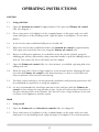
OPERATING INSTRUCTIONS
Caution!
Parts of the Stockton stove are manufactured from cast iron, which needs to be tempered
before the stove is operated at the highest temperatures. Therefore it is recommended that the
stove is operated at low temperatures for the first 24 hours of use.
During this time the appliance may give off some unpleasant odours, as the paint cures, and
we recommend that you keep the room well ventilated during this period to avoid a build-up
of fumes.
After a prolonged period of time without burning, such as the summer, it is recommended to
re-temper the castings by keeping the fire low for about 4 hours.
1. LIGHTING & BURNING THE STOVE
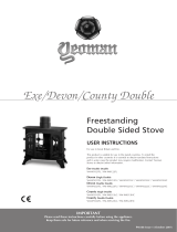
Diagram 1
Primary Air
Control
OPEN CLOSE
Airwash Air
control
OPEN CLOSE
Boiler Connections
(4x1”BSP)

11
OPERATING INSTRUCTIONS
Solid Fuel
1.1 Using solid fuel.
1.2 Open the Airwash air control to approximately 50% open and Primary air control
fully. See diagram 1.
1.3 Place some pieces of firelighters or dry crumpled paper on the grate and cover with
some small pieces of dry kindling wood. Light the paper or firelighters. Do not burn
plastics.
1.4 As the fire becomes established add pieces of solid fuel.
1.5 When the fire becomes established reduce the
Airwash air control to approximately
50% open and control the burn rate using the
Primary air control only.
1.6 Before re-fuelling the appliance it is advisable to first de-ash the firebed, using the
riddling grate system, operated by using removable handle to pull the riddling knob in
and out. This causes the ash to fall down into the ashpan.
1.7 Open the
Primary air control fully for a few minutes, to establish a glowing bed efore
adding new fuel.
1.8 Allow the new fuel to burn at high output for a few minutes before adjusting the burn
rate with the
Primary air control to the desired setting. It is best to refuel little and
often to maintain clean and efficient burning.
1.9 The ideal control settings to suit the particular installation and personal preferences will
be established by experience in using the appliance.
1.10 It is not recommended to load large amounts of fuel and burn with the Primary air
control
on low settings for long periods of time. As the will reduce the effectiveness of
the glass cleaning effect of the airwash. Also this will cause a large build-up of tars and
creosotes in the appliance and flue system.
Wood
1.1 Using wood
1.2
Open the
Primary air and Airwash air controls fully
. See diagram 1.
1.3 Place some pieces of firelighters or dry crumpled paper on the grate and cover with
small pieces of dry kindling wood. Light the paper or firelighters. Do not burn plastics.

12
OPERATING INSTRUCTIONS
1.4 As the fire becomes established add larger pieces of wood and close the Primary air
control
and control the burn rate using the Airwash air control only.
1.5 To burn wood efficiently it is best to allow a bed od ash to build-up on the grate, and
continue to control the combustion using the Airwash air control only.
1.6 Before re-fuelling the appliance it is advisable to first rake the embers evenly over the
firebed then open the Airwash air control fully for a few minutes, to establish a
glowing bed before adding new logs.
1.7 Allow the new logs to burn at high output for a few minutes before adjusting the burn
rate with the
Airwash air control to the desired setting. It is best to refuel little and
often to maintain clean and efficient burning.
1.8 The ideal control settings to suit the particular installation and personal preferences will
be established by experience in using the appliance.
1.9 It is not recommended to load large amounts of logs and burn with the
Airwash air
control
on low settings for long periods of time. This will reduce the effectiveness of
the glass cleaning effect of the Airwash air. Also this will cause a large build-up of tars
and creosotes in the appliance and flue system.
We would recommend that the Stockton is burnt at high output for at least 30 minutes
each day when it is in use. This will help reduce the build-up of tars and build-ups of tars
and creosotes within the appliance.
2. OPENING THE DOORS
2.1 To open the door, hook the tool provided over the door handle and rotate clockwise
1/4 turn. Do not force the handle to turn more than 1/4 turn as damage may occur.
2.2
Never open the door with your bare hands.
2.3 Closing the door is the reverse of the previous.

13
OPERATING INSTRUCTIONS
3. ASH REMOVAL
3.1 The burning of any fuel will produce ash, which will have to be removed after a period
of use. This time will depend on the fuel used. Before removing the ash from the
appliance it is advisable to let the fire burn down to a low level, or even go out
completely.
3.2 The ashpan can then be removed from the appliance using the tool provided and a
gloved hand.
3.3 As heat can remain in the ash for a long period after use, care must be taken when
removing and carrying the full ashpan. We suggest that the ash be placed directly in to
a Stovax ash caddie.
3.4 Do not place ash in a bin made from plastic or any other combustible material.
3.5
Failure to remove excess ash on a regular basis could cause damage to the Stockton
stove.

14
MAINTENANCE
1.GENERAL CLEANING
1.1 We would recommend that your Stockton stove be cleaned fully on a regular basis,
according to the level of use. Attention should be given to cleaning the flueways and
removing ash. Regular cleaning and preventive maintenance will help give many years
of safe use.
2. CLEANING GLASS
2.1 While the correct use of the Airwash system will generally keep the glass clean when
the appliance is used you may sometimes need to clean the glass.
2.2 This can be done as follows. Allow the Stockton stove to cool fully, never attempt to
clean hot glass. Any deposits can then be removed using a soft cloth and Stovax
Glass Cleaner.
2.3
Before re-lighting the appliance, dry the glass fully.
3. CHIMNEY SWEEPING
3.1 We would recommend that to maintain the safe and efficient use of the appliance the
flue / chimney is inspected and swept at least once a year
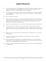
4. ANNUAL SERVICE
4.1 At the end of the heating season it is recommended to strip, inspect and clean the
appliance as detailed below.
4.2 Carefully remove all of the following internal parts. Complete grate and Ashpan.
4.3
Vacuum clean any remaining ash and debris from the inside of the stove.

15
MAINTENANCE
4.4 Clean the internal surfaces of the appliance using a wire brush and scraper as required.
Vacuum and brush the resulting debris from the stove then give the inside of the
appliance a protective coating of light oil, such as WD40®.
4.5 Clean the Grate parts with a wire brush, and check the parts for any damage. Replace
any damaged parts, if required, and coat all parts with a protective coating of light oil,
such as WD40®.
4.6 Re-fit cleaned internal parts.
4.7 Remove the glass from the door, and discard all old rope and strip seals. Clean the old
glue from the door sealing rope grove and remove dust and dirt. Clean the door glass
using Stovax Stove Glass Cleaner and a soft cloth, do not use abrasive cleaners to
remove tar or soot deposits from the glass.
4.8 Replace the glass edge seal with a new seal and re-fit the glass into place in the door.
4.9 Fit new door rope seal, gluing it in place with Stovax Thermic Seal rope adhesive.
When fitting new door seals we recommend closing the appliance door and leaving for
at least 12 hours before using. This allows the adhesive to fully bond to the seal before
use.
4.10 Lightly oil the door catch mechanism and hinge pins. Avoid getting oil on to the door
seals and glass.
4.11 To refresh the finish on painted appliances it is possible to re-paint using Stovax
Thermolac Stove paint.
4.12 We recommend that only genuine Stovax replacement parts are used to keep your
Stockton stove in safe and efficient working order. Your local Stovax dealer will be able
to provide you with the genuine parts you require.
4.13 Heating circuit parts should be maintained in accordance with the individual suppliers
recommendation.

16
MAINTENANCE
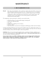
5. RECOMMENDED FUELS
Wood:- Burn only seasoned timber, with a moisture content of less than 20%. In most cases
this would require drying cut wood for 12 to 18 months before use. Poor quality
timber could cause low combustion efficiency, produce large amounts of harmful
condensation, which could reduce the effectiveness of the airwash system, and
ultimately the life of the appliance Do not burn painted, treated wood or
manufactured board products.
The symptoms of poor performance related to wet wood include:-
• difficulty getting a fire going and keeping it burning well
• smoky fires with little flame
• dirty glass
• rapid creosote build-up in the chimney
• low heat output
• Short burn times, excessive fuel consumption and blue/grey smoke from the chimney
To help avoid large build-ups of tars and creosote within in the stove and the flue system, it is
recommended to burn at maximum output for at least 30 minutes each day. The use of Stovax
Protector chimney cleaner will also help to reduce this problem.
Solid fuel:- Burn only manufactured smokeless fuels, or anthracite, listed as suitable for use
with closed heating appliances.
Do not burn ‘petro-coke’ or other petroleum based fuels, as
this will invalidate and product guarantee.
If you require advice on suitable solid fuels contact your local Approved Coal Merchant.
Details can be obtained by ringing the Solid Fuel Association advice line on Freephone
0800 600 000. Or their web site at www.solidfuel.co.uk

MAINTENANCE
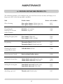
6. STOVAX STOVECARE PRODUCTS
The following products, all available from your local Stovax stove stockist, will help you to
keep your stove in the best possible condition.
Task Product name Stovax code number
Glass cleaning Stove glass cleaner (500ml wipe-on) 4111
Stove glass cleaner (500ml spray-on) 4103
Preventing the Protector (15 sachets) 7002
build-up of creosote
Protector (1kg tub) 7025
in the chimney
Sealing flue pipe joints
Fire cement (500g tub) 2020
Fire cement (600g cartridge) 2021
Re-painting Thermolac Black (400ml aerosol) 2019
Thermolac Black (200ml brush-on) 2057
Cleaning the surface Colloidal black (85ml) 7000
of matt black stoves
Protecting your hands
Heat-resistant leather gloves 4008
Sealing the stove door 14mm black rope seal (handy pack) 5000
14mm black rope seal (25m reel) 4670
Sealing the stove glass 3mm black rope seal (handy pack) 4975
3mm black rope seal (25m reel) 4974
Attaching rope seal Thermic seal (50ml bottle) 5037
17

18

19

Stovax Ltd, Falcon Road, Sowton Industrial Estate, Exeter, Devon, England EX2 7LF
Tel: (01392) 474011 Fax: (01392) 219932 E-mail: [email protected] www.stovax.com
-
 1
1
-
 2
2
-
 3
3
-
 4
4
-
 5
5
-
 6
6
-
 7
7
-
 8
8
-
 9
9
-
 10
10
-
 11
11
-
 12
12
-
 13
13
-
 14
14
-
 15
15
-
 16
16
-
 17
17
-
 18
18
-
 19
19
-
 20
20


Ask a question and I''ll find the answer in the document
Finding information in a document is now easier with AI
Related papers
-
Stovax 7126 User manual
-
-
-
-
-
-
-
-
-
Other documents
-
 Yeoman DEVON 50 User manual
-
Yeoman 210 User manual
-
 Yeoman YMMB User manual
-
 Firewarm stoves FIREWARM 12 Installation And Operating Instructions Manual
-
 Yeoman YM-W9121FL User manual
-
AGA Minsterley Solid Fuel boiler Stove Owner's manual
-
 Eco Range T3 Installation Instructions & User Manual
-
Charnwood Country 8B User manual
-
 Yeoman YM-CKWDPB-L User manual
-
Aspect PA14B1 Installation guide


