Page is loading ...
Multi-format camera
AK-HC931BP
Before attempting to connect, operate or adjust this product,
please read these instructions completely.
2
CAUTION:
This product uses a semiconductor laser system
and is a laser class 1 product complies with
Radiation Performance Standards, 21CFR
SUBCHAPTER J.
Use of controls or adjustments or performance
of procedures other than those specified herein
may result in hazardous radiation exposure.
Don’t make any modifications.
Don’t repair by yourself.
Refer servicing to qualified personnel.
CAUTION:
Invisible Laser radiation is emitted from the
Optical fiber connector when this product is
turned on.
Don’t look into directly into the Optical fiber
connector of this product.
indicates safety information.
CAUTION:
TO REDUCE THE RISK OF FIRE OR SHOCK
HAZARD AND ANNOYING INTERFERENCE, USE
THE RECOMMENDED ACCESSORIES ONLY.
WARNING:
• TO REDUCE THE RISK OF FIRE OR SHOCK
HAZARD, DO NOT EXPOSE THIS EQUIPMENT TO
RAIN OR MOISTURE.
• TO REDUCE THE RISK OF FIRE OR SHOCK
HAZARD, KEEP THIS EQUIPMENT AWAY FROM
ALL LIQUIDS. USE AND STORE ONLY IN
LOCATIONS WHICH ARE NOT EXPOSED TO THE
RISK OF DRIPPING OR SPLASHING LIQUIDS,
AND DO NOT PLACE ANY LIQUID CONTAINERS
ON TOP OF THE EQUIPMENT.
FCC Note:
This equipment has been tested and found to comply
with the limits for a class A digital device, pursuant to
Part 15 of the FCC Rules. These limits are designed
to provide reasonable protection against harmful
interference when the equipment is operated in a
commercial environment. This equipment generates,
uses, and can radiate radio frequency energy, and if
not installed and used in accordance with the
instruction manual, may cause harmful interference
to radio communications. Operation of this equipment
in a residential area is likely to cause harmful
interference in which case the user will be required to
correct the interference at his own expense.
Warning:
To assure continued FCC emission limit compliance,
the user must use only shielded interface cables when
connecting to external units. Also, any unauthorized
changes or modifications to this equipment could void
the user’s authority to operate it.
For your safety
CAUTION
RISK OF ELECTRIC SHOCK
DO NOT OPEN
CAUTION: TO REDUCE THE RISK OF ELECTRIC SHOCK,
DO NOT REMOVE COVER (OR BACK).
NO USER SERVICEABLE PARTS INSIDE.
REFER TO SERVICING TO QUALIFIED SERVICE PERSONNEL.
The lightning flash with arrowhead symbol,
within an equilateral triangle, is intended to
alert the user to the presence of uninsulated
“dangerous voltage” within the product’s
enclosure that may be of sufficient magnitude
to constitute a risk of electric shock to
persons.
The exclamation point within an equilateral
triangle is intended to alert the user to the
presence of impor tant operating and
maintenance (service) instructions in the
literature accompanying the appliance.
This class A digital apparatus complies with
Canadian ICES-003.
Cet appareil numérique de la classe A est
conforme à la norme NMB-003 du Canada.
For CANADA
This product contains a CR Coin Cell Lithium Battery
which contains Perchlorate Material
— special
handling may apply.
See www.dtsc.ca.gov/hazardouswaste/perchlorate.
3
indicates safety information.
For your safety
1) Read these instructions.
2) Keep these instructions.
3) Heed all warnings.
4) Follow all instructions.
5) Do not use this apparatus near water.
6) Clean only with dry cloth.
7) Do not block any ventilation openings. Install in
accordance with the manufacturer’s instructions.
8) Do not install near any heat sources such
as radiators, heat registers, stoves, or other
apparatus (including amplifiers) that produce heat.
9) Do not defeat the safety purpose of the polarized
or grounding-type plug. A polarized plug has two
blades with one wider than the other. A grounding-
type plug has two blades and a third grounding
prong. The wide blade or the third prong are
provided for your safety. If the provided plug does
not fit into your outlet, consult an electrician for
replacement of the obsolete outlet.
10) Protect the power cord form being walked on or
pinched particularly at plugs, convenience
receptacles, and the point where they exit from
the apparatus.
11) Only use attachments/accessories specified by
the manufacturer.
12) Use only with the cart, stand, tripod,
bracket, or table specified by the
manufacturer, or sold with the
apparatus. When a cart is used, use
caution when moving the
cart/apparatus combination to avoid
injury from tip-over.
13) Unplug this apparatus during lightning storms or
when unused for long periods of time.
14) Refer all servicing to qualified service personnel.
Servicing is required when the apparatus has
been damaged in any way, such as power-supply
cord or plug is damaged, liquid has been spilled or
objects have fallen into the apparatus, the
apparatus has been exposed to rain or moisture,
does not operate normally, or has been dropped.
Read these operating instructions carefully before using the unit. Follow the safety instructions on the unit and the
applicable safety instructions listed below. Keep these operating instructions handy for future reference.
IMPORTANT SAFETY INSTRUCTIONS

4
Contents
For your safety ........................................................................................................................................................... 2
Overview ....................................................................................................................................................................
5
Features ....................................................................................................................................................................
5
Controls and their functions ....................................................................................................................................... 6
Mounting the lens .................................................................................................................................................... 11
Adjusting the lens flange back .................................................................................................................................
12
Performing the viewfinder adjustments ....................................................................................................................
13
Connecting the microphone ..................................................................................................................................... 15
Mounting the camera on a tripod .............................................................................................................................
16
Component system configuration ............................................................................................................................
17
System connections 1 (with multi-format camera) ...................................................................................................
19
System connections 2 (with build-up unit) ...............................................................................................................
20
System connections 3 (with MSU) ........................................................................................................................... 21
Status displays on viewfinder screen .......................................................................................................................
22
Menu operations ......................................................................................................................................................
23
Setting menu configuration ......................................................................................................................................
25
How to select the video format ................................................................................................................................
28
AK-HC931BP connector pin assignment ................................................................................................................. 29
External dimension drawings ...................................................................................................................................
30
Specifications .......................................................................................................................................................... 31

5
This new-generation HD camera is designed to support the 720P or 1080I format.
The 720P or 1080I video format can be selected using the menu settings. This model uses newly developed 2/3
CCDs with a
million pixels [1280 (H)
720 (V)]. By taking a fresh approach to the on-chip lens, CCD structure and processes, these new
CCDs embody dramatically improved sensitivity, smear and dynamic range specifications compared with conventional CCDs,
and they achieve a high performance which is on a par with that of SD. Furthermore, the moire in the band has been slashed by
offsetting the pixels by combining Panasonic’s unique horizontal line readout CCDs with high-accuracy signal processing.
The newly developed digital signal processing LSI which supports 12-bit A/D conversion and which is provided in the camera
head processes the gamma, knee, detail, matrix and other process signals and uses a new system for CCD defect correction
to achieve improved operability with a greater number of functions, high quality and high stability which only digital systems can
deliver. The 12-bit A/D converter yields a stable wide dynamic circuit with a high signal-to-noise ratio from the dark areas to the
highlights.
A newly developed casing is used to house the multi-format camera head to achieve a compact size and light weight. The
amount of heat generated has been significantly reduced by designing the new circuitry to consume less power and by adopting
an efficient heat dissipation design for the new casing.
SD signals (D1, VBS) can be output and RET images and PROMPT signals can be input by connecting the multi-format camera
to the CCU (AK-HCU931P, optional accessory).
In terms of controlling the camera’s functions, the ROP (AK-HRP931P) or MSU (AK-MSU930P), also available as an optional
accessory, can be connected to the CCU to control such analog functions as the camera head’s pedestal and iris and to control
such switches as the gain and output selector switches.
720P and 1080I video formats supported
Either the 720P or 1080I video format can be selected
using the menu settings.
The camera can be connected to existing peripheral
devices no matter which video format is selected.
Newly developed 720P, 2/3
million-pixel CCDs
incorporated
This achieves a high sensitivity that surpasses the
standard sensitivity of F10 and is on a par with SD.
Smear has been cut to 130 dB and the number of
white marks has been drastically reduced by process
improvements.
H-CCD drive is accomplished at a frequency of 74 MHz to
attain a high response and high resolution.
Digital signal processing LSI with high picture quality
featured in the camera unit
After the process circuits, the signals undergo 12-bit,
74 MHz high-picture-quality digital processing, yielding a
high reliability, more functions and enhanced operating
ease as a result.
Multi-functional enhancer
In addition to the many functions such as chroma DTL,
skin DTL and dynamic DTL, there is a choice of 8 boost
frequencies. (For both HD and SD)
Designed to achieve low noise levels of below NC15
The fan mode can be switched to suit the application at
hand, and measures to reduce the power requirements
and improve the heat dissipation were adopted in the final
design.
Fuller complement of control circuits and auto setup
(ASU) function
The self-diagnosis functions have been enhanced, and it
has now become possible to select the ASU function by
combining the external shooting chart and internal test
signals as well as the normal, simplified or other mode.
Peripheral components
Ease of operation can be further improved by configuring
a system where the multi-format camera is used in
combination with the remote operation panel (ROP) and
master setup unit (MSU).
Using the ROP matrix, for instance, ROP assignment is
enabled without connector patch switching.
Data trunk function
Two RS-422 circuits are provided as a standard feature.
They obviate the need for the cables used with virtual
control, pan/tilt head and lens control, etc.
D/C output of camera supported (optional function)
The VF output or camera output can be selected as the
D/C output.
The VF images can be monitored on the NTSC LCD
monitor.
VF signals output in 1080I format
Regardless of whether 720P or 1080I is selected as the
format, the VF signals are output in the 1080I format so
there is no need to provide two viewfinders.
Overview
Features
6
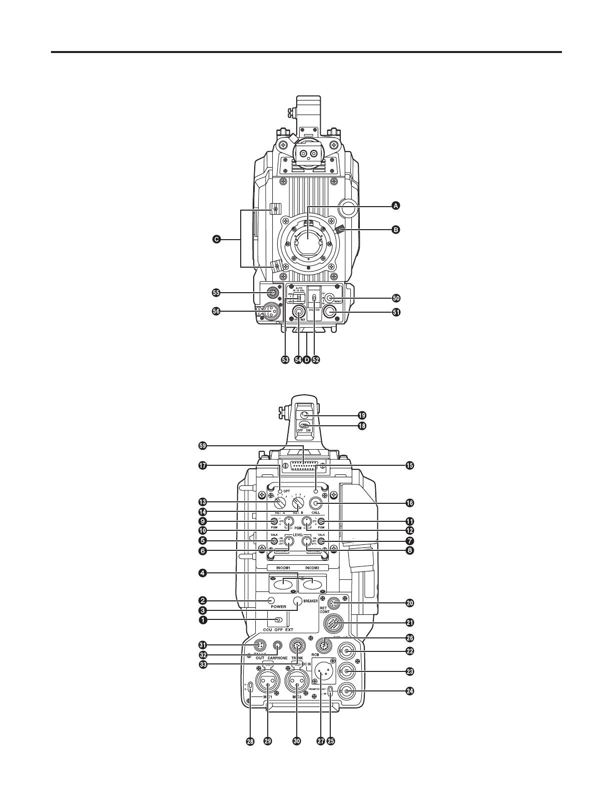
Controls and their functions
7
Controls and their functions

8
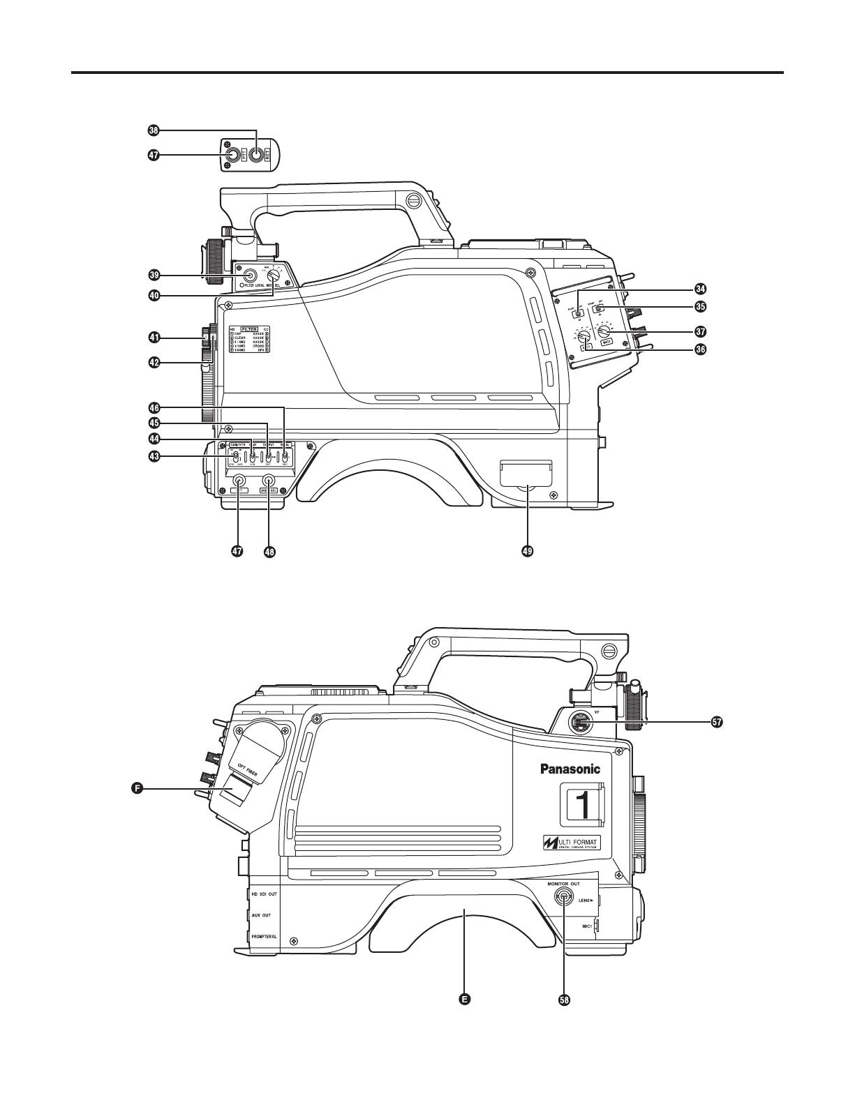
Lens mount (Bayonet type)
This is where the lens is mounted.
Lens clamp lever
The lens is inserted into the lens mount , and this lever
is then turned to clamp the lens in place.
Lens cable and mic cable clamps
These are used to clamp the lens cable and mic cable in
place.
Tripod mount
Before securing the multi-format camera to a tripod,
attach the tripod adapter (SHAN-TM700) which is
available as an optional accessory.
Shoulder pad
Adjust this pad in such a way that the multi-format
camera can be operated easily when carried on the
shoulder.
The pad position can be moved forward or backward
once the two fixing screws are loosened.
Optical fiber connector (EDW.3K made by LEMO)
Camera power switch [POWER]
This is used to select the camera power input (power
supplied from the CCU or from an external connector)
and turn the power ON and OFF.
Power LED
This lights up red when power is supplied to the camera.
Power circuit breaker [BREAKER]
When an overcurrent flows to the camera, the breaker is
tripped, and the power supply is cut off.
INCOM connectors 1, 2 [INCOM1, INCOM2]
The INCOM or headset plugs are connected here.
INCOM1 MIC ON/OFF switch [MIC1 TALK]
This is the INCOM1 MIC ON/OFF selector switch.
INCOM1 level control [INCOM1 LEVEL]
This is used to adjust the INCOM1 receive level.
INCOM2 MIC ON/OFF switch [MIC2 TALK]
This is the INCOM2 MIC ON/OFF selector switch.
INCOM2 level control [INCOM2 LEVEL]
This is used to adjust the INCOM2 receive level.
INCOM1 PGM selector switch [INCOM1 PGM]
This is used to select the PGM to be mixed with INCOM1.
INCOM1 PGM level control [INCOM1 PGM]
This is used to adjust the INCOM1 and PGM mixing level.
INCOM2 PGM selector switch [INCOM2 PGM]
This is used to select the PGM to be mixed with INCOM2.
INCOM2 PGM level control [INCOM2 PGM]
This is used to adjust the INCOM2 and PGM mixing level.
RET-A selector switch [RET A]
This switch is used to select the return images to be
switched by RET-A.
RET-B selector switch [RET B]
This switch is used to select the return images to be
switched by RET-B.
CALL LED
This lights when the CALL switch is pressed. It also lights
in response to a call from the ROP or MSU.
CALL switch [CALL]
This lights the CALL LED on the ROP or MSU and
sounds the buzzer.
OPT LED
This indicates the camera’s optical signal reception
status. It normally lights up green. When any problem has
occurred, it lights up red.
Back tally LED selector switch
This is used to set the back tally LED to ON or OFF.
Back tally LED
This lights when the tally signal is supplied.
RET switching control connector [RET CONT]
The cable of the RET switching box (optional accessory)
is connected here for controlling the ON/OFF settings of
RET1, 2, 3 and INCOM1 MIC.
Build-up unit connector [EXT I/O]
The cable from the build-up unit (optional accessory) is
connected here.
Camera main line SDI output connector (BNC)
[HD SDI]
The camera main line’s HD-SDI images are output from
this connector.
Optional video output connector (BNC) [AUX OUT]
When the camera D/C unit (AK-HDC931, optional
accessory) has been installed, the camera’s D/C images
(VBS) are output from this connector.
Genlock sync input/PROMPT output connector
[PROMPT/GL]
When the GL/PROMPT selector switch is set to GL, the
reference signal (tri-level SYNC) which is used to genlock
the camera is input to this connector; when it is set to
PROMPT, the images input from the CCU are output from
this connector.
GL/PROMPT selector switch
This is used to select the genlock input or the input/output
(genlock input and PROMPT output) signals of the
PROMPT output connector.
Controls and their functions

9
RCB connector [RCB]
The simplified remote control unit (RCB, optional
accessory) is connected to this connector.
External power supply input connector [DC IN]
The input of the external DC power supply is connected
to this connector. (DC 12V)
MIC1 selector switch [MIC1 F/R]
This is used to switch the MIC1 input signal to the front
or rear.
Rear MIC1 connector [MIC1]
An audio component or microphone is connected to this
connector.
Rear MIC2 connector [MIC2]
An audio component or microphone is connected to this
connector.
Tally output connector [TALLY OUT]
The R or G tally signal is output from this connector
(open collector). A DC 12 V voltage (approx. 1.0 A) can
also supplied.
Earphone jack [EARPHONE]
When an earphone (optional accessory) is connected to
this jack, the INCOM1 receive signal and MIC1 monitor
signal can be heard.
Data trunk connector [TRUNK]
The trunk data [RS-422 2] of the CCU is input to and
output from this connector.
MIC1 power selector switch
This is used to select what kind of power is to be supplied
to MIC1. (The switch is set to phantom 48 V, AB 12 V or
OFF.)
MIC2 power selector switch
This is used to select what kind of power is to be supplied
to MIC2. (The switch is set to phantom 48 V, AB 12 V or
OFF.)
MIC1 Input gain selector switch
This is used to set the MIC1 input gain (in 10 dBm
increments from –20 to 60 dBm).
MIC2 input gain selector switch
This is used to set the MIC2 input gain (in 10 dBm
increments from –20 to 60 dBm).
RET selector switch [RET]
This is used as return image selector switch.
Optical filter selector switch [FILTER LOCAL]
This is pressed to adjust the optical filter manually.
When it is pressed again, the optical filter can be
controlled by the ROP.
Monitor output selector switch [MONI SEL]
This is used to select the images (Y/C, NAM, R, G, B)
which are to be output from the monitor output connector.
ND filter selector knob
This is used to adjust the optical filter manually when
LOCAL has been selected as the filter setting.
1: CAP, 2: Through, 3: 1/4, 4: 1/16, 5: 1/64
CC filter selector knob
This is used to adjust the optical filter manually when
LOCAL has been selected as the filter setting.
A: 3200K, B: 4300K, C: 6300K, D: Cross, E: DFO
Power save switch [CAM/VTR]
This is used to select the power supply status when VTR
recording has been temporarily stopped. It is not effective
when the CCU is connected to the camera.
Gain selector switch [GAIN]
This is used to select the gain for the camera images. It is
not effective when the CCU is connected to the camera.
Camera output selector switch [OUTPUT]
This is used to select the video output (CAM, BAR or
TEST). It is not effective when the CCU is connected to
the camera.
White balance selector switch [W.BAL]
This is set when there is no time to perform the coarse
adjustment of the white balance. It is not effective when
the CCU is connected to the camera.
PTT switch [PTT]
This selector switch is used to set the INCOM1 MIC to
ON or OFF.
Assignable switch [USER SEL]
Using the setting menu, user settings can be assigned
to this switch. When the switch is pressed, the assigned
user setting mode is established; when it is pressed
again, the selected mode is released.
SD card connector [SD CARD]
The setup card (optional accessory) is inserted here. For
details on its operation, refer to the menu.
Menu switch [MENU]
When this switch is pressed, the camera’s user menu is
output; when it is pressed again, the menu screen display
is cleared.
Controls and their functions

10
Lens connector [LENS]
The lens cable is connected to this connector.
Front MIC1 connector [MIC1]
A microphone (optional accessory) is connected here.
The power supply for the microphone can be connected
from this connector. What kind power is to be supplied is
set using the MIC1 power selector switch.
VF connector [VF]
The viewfinder cable is connected to this connector.
Monitor output connector (BNC) [MONITOR OUT]
The video signals for the monitor are output from this
connector. The images to be output are selected using
the monitor output selector switch.
Rear VF connector
This D-sub connector is used for viewfinder interface.
JOG dial button
Turning the JOG dial while the menu screen is displayed
moves the cursor to the setting items. The menu settings
are established by operating this dial button.
For details on the menu operations, refer to the section
on the menu operations.
Electronic shutter selector switch [SHUTTER]
This is set to ON when the electronic shutter is to be
used. When it is set to the SEL position, the shutter
speed is switched in the preset range and the mode
is also switched. It is not effective when the CCU is
connected to the camera.
AWB/ABB start switch [AUTO W/B BAL]
This switch is operated when the white balance (AWB) or
black balance (ABB) is to be adjusted automatically. It is
not effective when the CCU is connected to the camera.
VTR start/RET selector switch [VTR/RET]
This is used as the REC start switch of the VTR and
return image selector switch. It performs the same
operations as the VTR button of the lens. Its function can
be allocated as desired on the menu.
Controls and their functions

11
2 Align the center mark on the lens with the groove at the
top center of the lens mount, and mount the lens.
3 Lower the lens clamp lever to clamp the lens in place.
4 Insert the cable into the cable clamp and connect it to
the LENS connector.
<Notes>
For details on handling the lens, refer to the instructions
that accompany the lens.
Depending on the lens mounted, it may be necessary to
perform the following lens and camera adjustments.
1. Flange back adjustment for the lens
2. Auto iris operation speed adjustment for the lens
3. White shading adjustment for the lens (performed using
the controls on the camera)
1 Raise the lens clamp lever, and remove the mount cap.
Mount cap
Lens clamp lever
Center mark
LENS connector
Mounting the lens
12
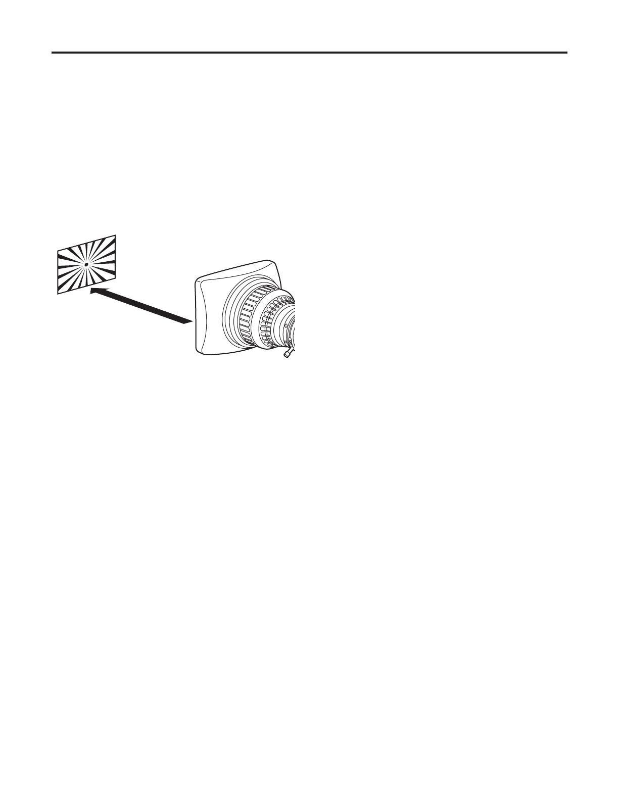
Adjust the flange back (distance from the surface where
the lens is mounted to the surface where the images
are formed) if the subject fails to be precisely focused at
both the telephoto and wide-angle settings when zoom
operations are to be performed.
Once adjusted, the flange back does not need to be
adjusted again unless the lens is replaced.
Adjustment method
1 Mount the lens on the camera. Do not forget to connect
the lens cable at this time.
2 Set the lens iris to manual, and open the iris.
3 Set the lighting in such a way that the appropriate video
output level is obtained at a distance of about 10 ft
(3 meters) from the flange back adjustment chart.
If the video level is too high, use a filter or shutter.
4
Loosen the screw that secures the F.f (flange focus) ring.
<Note>
Depending on the lens concerned, this ring may be
marked as the F.b (flange back) ring.
5 Set the zoom ring to the telephoto position either by
manual or electrical means.
6 Shoot the flange back adjustment chart, and turn the
distance ring to adjust the focus.
7 Set the zoom ring to the wide-angle position, and turn
the F.f ring to adjust the focus. Take care not to move
the distance ring.
8 Repeat steps 5 to 7 until the chart is focused properly at
both the telephoto and wide-angle positions.
9 Tighten up the screw that secures the F.f ring.
<Note>
For details on the adjustment method and positions of the
lens parts, refer also to the instructions that accompany the
lens.
About 10 ft (3 m)
Adjusting the lens flange back
13
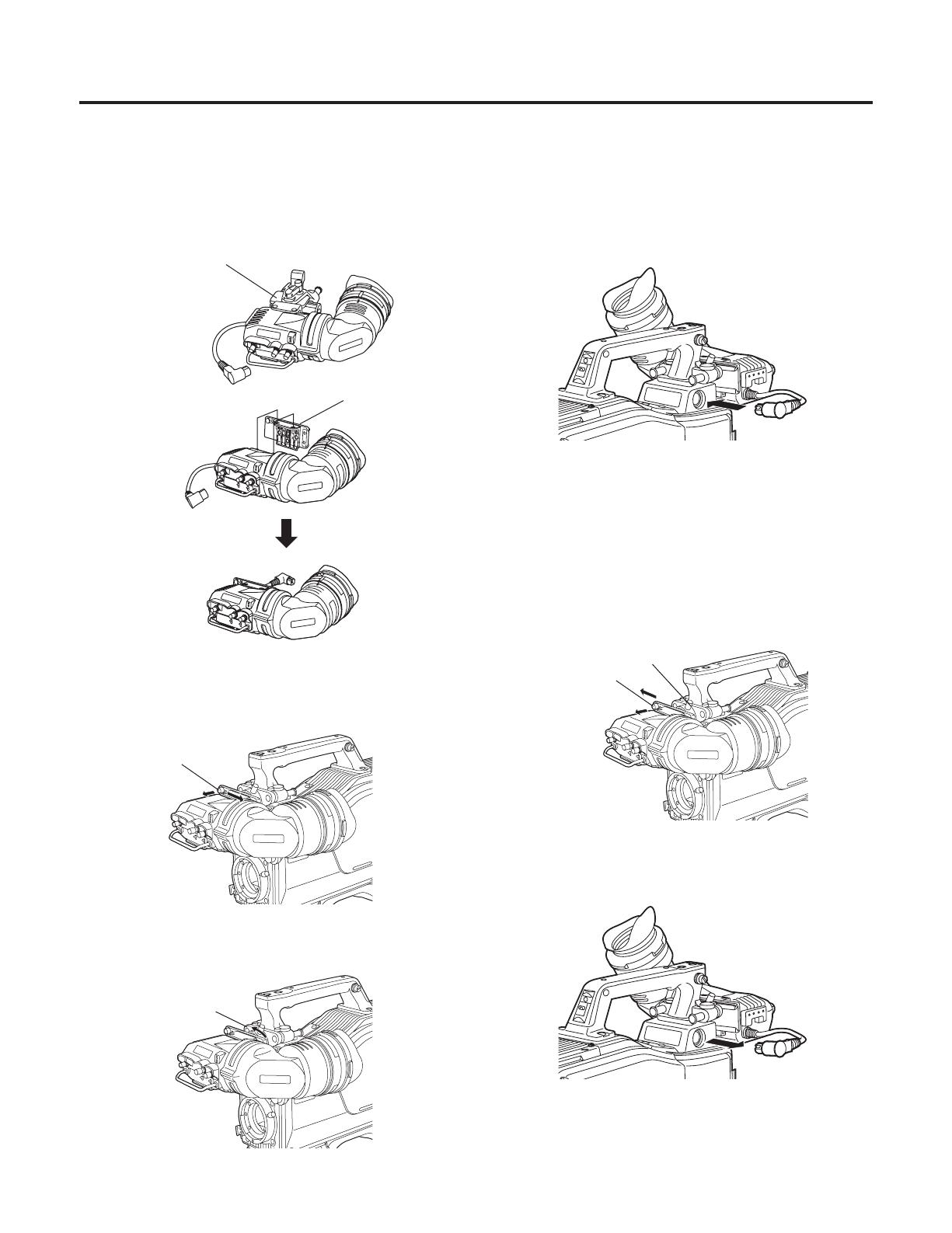
Attaching the viewfinder
Stopper screw
1 Check that the camera’s POWER switch is at the OFF
position.
2 Attach the accessory mounting plate to the viewfinder.
5 Connect the plug to the viewfinder’s connector.
<Note>
When connecting the plug to the viewfinder’s connector,
ensure that it is fully and securely inserted.
3 Pull up the knob on the mounting plate and slide the
plate to attach the viewfinder.
4 Tighten the stopper screw securely.
Detaching the viewfinder
1 Check that the camera’s POWER switch is at the OFF
position.
2 Loosen the stopper screw, pull up the knob on the
mounting plate and slide the viewfinder along and off the
plate.
3 Disconnect the plug from the viewfinder cable connector.
Remove mounting
plate from the
viewfinder.
Mounting
plate
supplied to
AK-HC931BP
Pull up the knob.
Stopper screw
Pull up the knob.
Performing the viewfinder adjustments
(The viewfinder is an optional accessory.)

14
Left or right position adjustment
1 Loosen the stopper screw.
2 Move the viewfinder to the left or right to adjust its position.
3 Tighten the stopper screw.
1 Rotate the viewfinder forward/backward position fixing
lever towards the outside to release it from the locked
position.
2 Move the viewfinder forward or backward to adjust its
position.
3 Rotate the viewfinder forward/backward position fixing
lever in the opposite direction until it locks.
Lever
Viewfinder
Forward or backward position adjustment
Viewfinder
Stopper screw
Stopper screw
Performing the viewfinder adjustments
(The viewfinder is an optional accessory.)
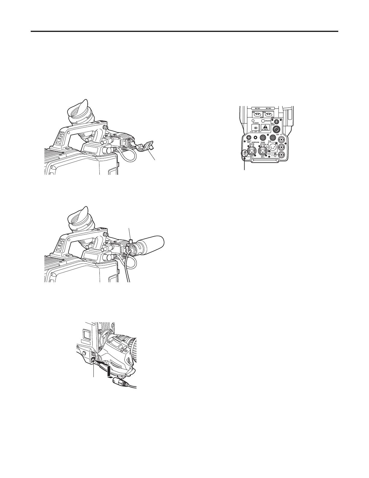
15
1 Open the microphone holder.
2 Mount the microphone and tighten up the clamp screw.
3 Connect the microphone cable to the MIC IN connector
on the camera.
When the microphone is mounted on the
viewfinder (optional accessory) for use
The microphone of the microphone kit AJ-MC700P (optional
accessory) can be mounted on the viewfinder.
MIC IN connector
Microphone
holder
Clamp screw
4 If the audio channel whose signals are to be recorded so
requires, set the AUDIO IN switch to F.
AUDIO IN switch
Connecting the microphone
16
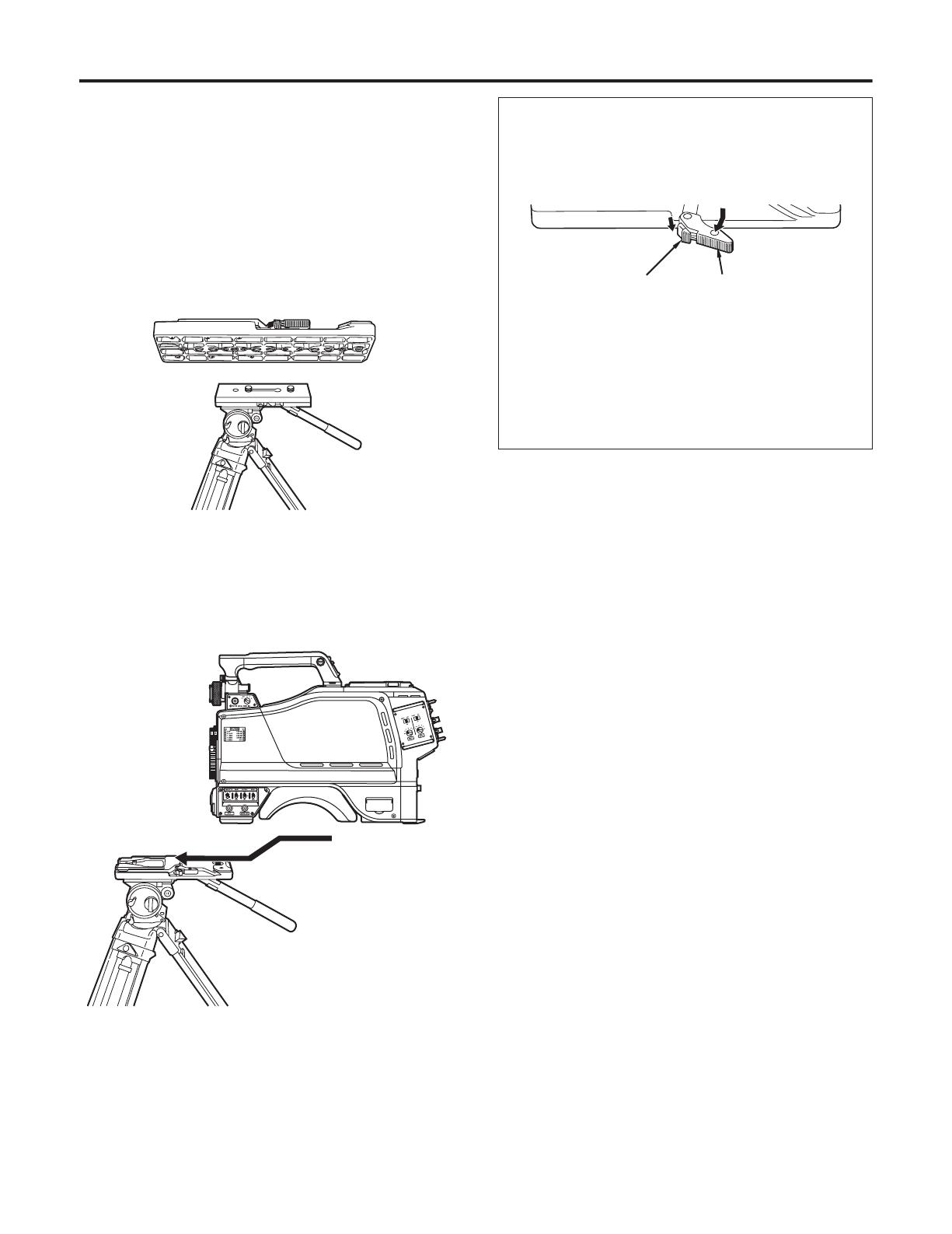
1 Mount the tripod attachment on the tripod.
<Note>
Consider the center of gravity of the camera and tripod
together when selecting the holes for attaching the
camera. Check that the diameter of the selected holes
match the diameter of the screws on the tripod platform.
2 Mount the camera on the tripod attachment. Slide the
camera toward the front along the groove until a click is
heard.
Use the tripod attachment, available as an optional
accessory, to mount the camera on a tripod.
Tripod platform
Tripod attachment
Detaching the camera from the tripod attachment
While pushing the red lever, move the black lever in the
direction of the arrow, and slide the camera toward the
back.
<Note>
If the pin of the tripod attachment fails to return to its
original position after the camera has been detached,
push the red lever again and simultaneously move the
black lever in the direction of the arrow to return the pin to
its original position.
Bear in mind that the camera cannot be mounted if the pin
still remains at the center.
Red lever
Tripod attachment
Black lever
Mounting the camera on a tripod
17
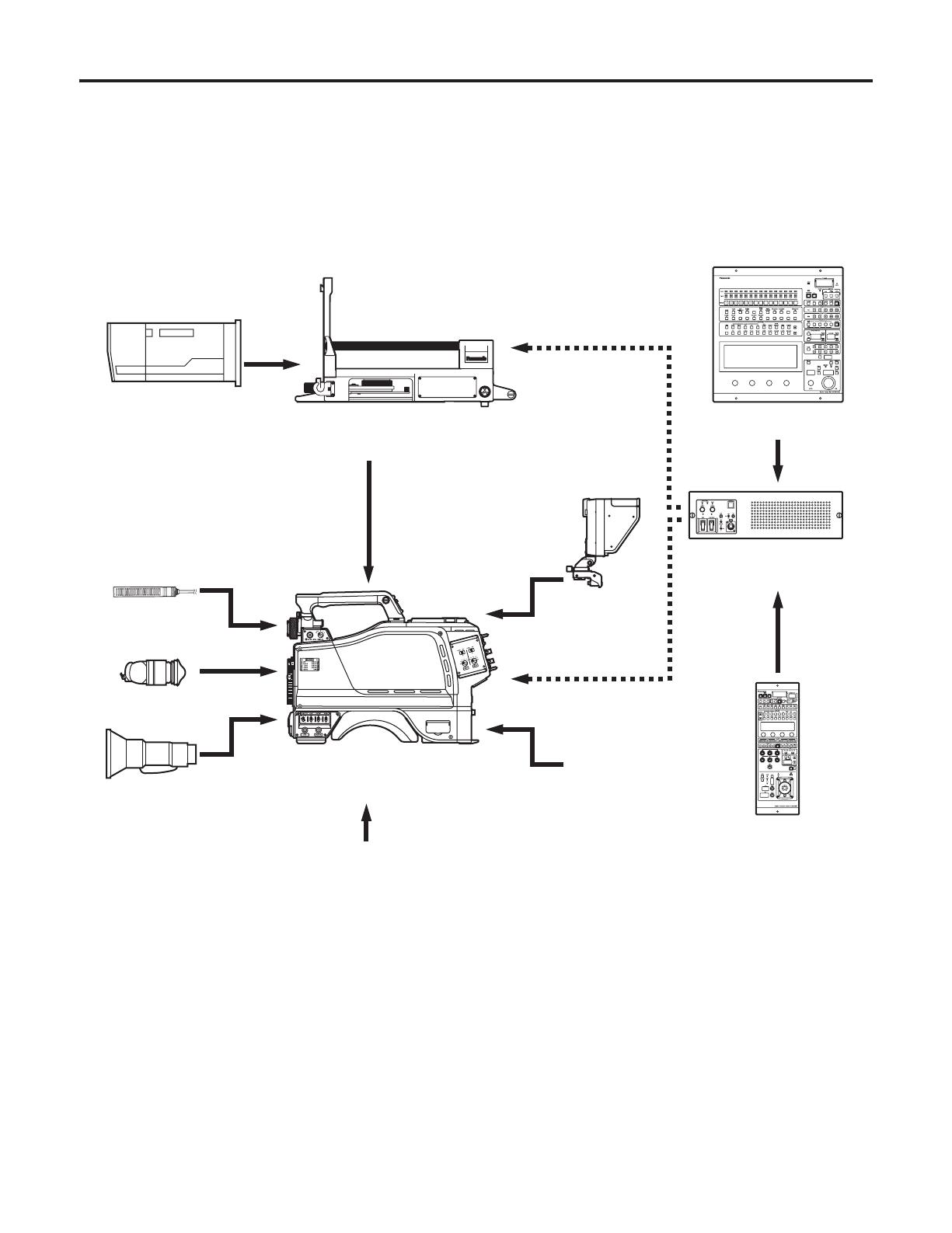
An example of the standard system consisting of the multi-format camera (AK-HC931BP) and peripheral components is
described below and shown on the following page. The MSU (AK-MSU930P) is not required unless a multiple number of
cameras are to be controlled.
The basic system configuration includes the lens, multi-format camera, 2
viewfinder, camera control unit (CCU) and remote
operation panel (ROP).
System block diagram
2 black-and-white
viewfinder
AJ-HVF20P
Build-up unit
AK-HBU931P
Large lens
Microphone kit
AJ-MC700P
Handy lens
Multi-format camera
AK-HC931BP
Tripod attachment
SHAN-TM700
SD memory card
RP-SD008B
Master setup unit
AK-MSU930P
8 LCD viewfinder
AK-HVF931P
Remote operation panel
AK-HRP931P
Camera control unit
AK-HCU931P
ROP cable
Component system configuration

18
Outline of peripheral components
1 Camera control unit (CCU: AK-HCU931P)
This is the multi-format camera’s camera control unit. It
is connected to the multi-format camera using an optical
fiber cable (optional accessory).
As a standard feature, it supports SD video input and
output, and it can also support HD video input and
output by connecting the HD output unit (AK-HHD931P).
2 Remote operation panel (ROP: AK-HRP931P)
The ROP is connected to the CCU using the ROP cable
(optional accessory), and enables the camera, CCU and
lens to be operated by remote control.
3 Master setup unit (MSU: AK-MSU930P)
When a multiple number of cameras and CCUs are
used, the MSU can operate up to 15 units either
separately or simultaneously by remote control. It can be
operated together with the ROP.
4 2 viewfinder (2VF: AJ-HVF20P)
This is the viewfinder for the multi-format camera.
5 Build-up unit (AK-HBU931P)
This is an adapter used to mount a larger lens (optional
accessory) on the multi-format camera. Thereby, it
affords the same level of operability as that provided by a
larger camera.
6 LCD viewfinder (LCD VF: AK-HVF931P)
This is the LCD viewfinder for the multi-format camera. It
can be used at the same time as the 2 viewfinder. It can
still be operated when the system is built up.
Component connections in an SD system
1 Component connections
Refer to pages 19 to 21 for the component connections.
After all the components have been connected (the
monitor system may be connected afterward), set the
CCU’s main power switch to the ON position. Then turn
on the camera’s power switch.
Component system configuration

19
Before proceeding with the connections, set the CCU power switch to the OFF position.
Connect the multi-format camera to the CCU.
Connect the ROP cable to the CCU and ROP.
When the camera power switch is set to ON after the CCU main power switch has been set to ON, the camera can be
controlled using the ROP.
Upon completion of shooting, set the CCU camera power switch and main power switch to OFF.
2 viewfinder
AJ-HVF20P
Lens
Multi-format camera
AK-HC931BP
ROP cable
Remote operation panel
AK-HRP931P
Camera control unit
AK-HCU931P
System connections 1 (with multi-format camera)
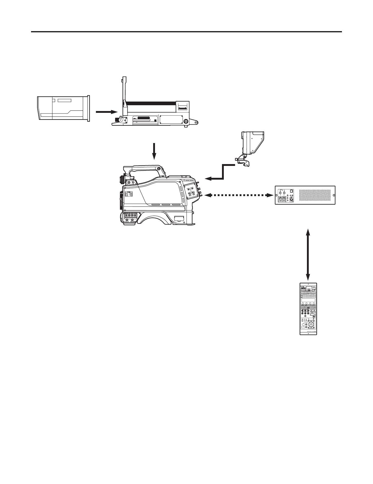
20
Large lens
Build-up unit
AK-HBU931P
8 LCD viewfinder
AK-HVF931P
Multi-format camera
AK-HC931BP
Remote operation panel
AK-HRP931P
Camera control unit
AK-HCU931P
ROP cable
System connections 2 (with build-up unit)
/