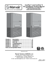
MODELS AVP 24-30-36-42-48-60
ModPac II™
Vertical Modular Wall-Mount
Air Conditioners
Installation and Operation Manual
1. Description ........................................ 5
2. Installation ........................................
8
3. Start-Up ...........................................
19
4. Troubleshooting ................................
20
5. Ratings&Specications ....................
24
6. Maintenance .....................................
27
7. Warranty ..........................................
28
Exploded Views & Parts Lists ...................29
P/N 81021 9/09-15
supersedes manual dated 2/08-14
Supporting Member of
Manufactured By:
Marvair
®
Division of AIRXCEL
®
, Inc.
P.O. Box 400 • Cordele, Georgia 31010
156 Seedling Drive • Cordele, Georgia 31015
(229) 273-3636 • Fax (229) 273-5154
E-mail: marvairtech@airxcel.com • Internet: www.marvair.com
The most current version of this manual can be found at www.marvair.com.

2
ModPac II, 9/09-15
Specicationssubjecttochangewithoutnotice.
© 9/09 Marvair
®
How To Use This Manual
This manual is intended to be a guide to Marvair's MODPac
™
line of vertical air conditioners. It contains
installation, troubleshooting, maintenance, warranty, and application information. The information
contained in this manual is to be used by the installer as a guide only. This manual does not supersede
or circumvent any applicable national or local codes.
If you are installing the MODPac
™
unit, rst read Chapter 1 and scan the entire manual before begin-
ning the installation as described in Chapter 2. Chapter 1 contains general, descriptive information and
provides an overview which can speed up the installation process and simplify troubleshooting.
If a malfunction occurs, follow this troubleshooting sequence:
1. Make sure you understand how the MODPac
™
unit works (Chapters 1 & 3).
2. Identify and correct installation errors (Chapter 2).
3. Refer to the troubleshooting information in Chapter 4.
If you are still unable to correct the problem, contact the Factory at 1-800-726-2734 for additional
assistance.
Please read the following “Important Safety Precautions” before beginning any work.
Important Safety Precautions
1. USE CARE when LIFTING or TRANSPORTING equipment.
2. TRANSPORT the UNIT UPRIGHT. Laying it down on its side may cause oil to leave the compres
-
sor and breakage or damage to other components.
3. TURN ELECTRICAL POWER OFF AT THE breaker or fuse box BEFORE installing or working
on the equipment. LINE VOLTAGES ARE HAZARDOUS or LETHAL.
4. OBSERVE and COMPLY with ALL applicable PLUMBING, ELECTRICAL, and BUILDING
CODES and ordinances.
5. SERVICE may be performed ONLY by QUALIFIED and EXPERIENCED PERSONS.
* Wear safety goggles when servicing the refrigeration circuit
* Beware of hot surfaces on refrigerant circuit components
* Beware of sharp edges on sheet metal components
* Use care when recovering or adding refrigerant
6. Use COMMON SENSE - BE SAFETY-CONSCIOUS
This is the safety alert symbol . When you see this symbol on the MODPac unit and in the
instruction manuals be alert to the potential for personal injury. Understand the signal word
DANGER, WARNING and CAUTION. These words are used to identify levels of the serious
-
ness of the hazard.
Failure to comply will result in death or severe personal injury and/or
property damage.
Failure to comply could result in death or severe personal injury and/or
property damage.
Failure to comply could result in minor personal injury and/or property
damage.
IMPORTANT
is used to point out helpful suggestions that will result in improved installation,
reliability or operation.
!
DANGER
!
WARNING
!
CAUTION

3
ModPac II, 9/09-15
Table of Contents
ModPac II™ A/C Description & Specs
1.1 General Description ....................................................................................................................... 5
1.2 General Operation ......................................................................................................................... 6
1.3 Electrical Diagrams ....................................................................................................................... 6
Installation
2.1 Equipment Inspection .................................................................................................................... 8
2.2 Installation Requirements .............................................................................................................. 8
2.3 Installation Materials ...................................................................................................................
11
2.4 Porting and Duct Work ................................................................................................................
12
2.5 Fresh Air Hood Installation ......................................................................................................... 13
2.6 "V" Damper Installation .............................................................................................................. 14
2.7 Bracket Installation ..................................................................................................................... 14
2.8 Mounting the Unit .......................................................................................................................
15
2.9 Electrical Connections .................................................................................................................
16
Start-Up
3.1 Check-Out of Cooling Cycle .......................................................................................................19
3.2 Check-Out of Heating Cycle ........................................................................................................19
Troubleshooting
4.1 Overview ......................................................................................................................................20
4.2 Failure Symptoms Guide ..............................................................................................................21
4.3 Compressor Troubleshooting .......................................................................................................22
4.4 Electric Heat Controls ..................................................................................................................23
Ratings & Specications
5.1 Ratings & Specications .............................................................................................................24
5.2 Dimensional Data .........................................................................................................................25
WARNING
• If the information in these instructions are not followed exactly, a re may result
causing property damage, personal injury or loss of life.
• Read all instructions carefully prior to beginning the installation. Do not begin
installation if you do not understand any of the instructions.
• Improper installation, adjustment, alteration, service or maintenance can cause
property damage, personal injury or loss of life.
• Installation and service must be performed by a qualied installer or service
agency in accordance with these instructions and in compliance with all codes
and requirements of authorities having jurisdiction.
INSTALLER: Affix the instructions on the inside of the building adjacent to the
thermostat.
END USER: Retain these instructions for future reference.

4
ModPac II, 9/09-15
Periodic Maintenance Requirements
6.1 Scheduled Maintenance ............................................................................................................... 27
Warranty Information
7.1 Warranty Statement ......................................................................................................................28
Exploded Views & Parts Lists .............................................................................................................29
Illustrations
Figure 1. Typical Electric Schematic ........................................................................................... 7
Figure 2. Damper Air Path ......................................................................................................... 10
Figure 3. Fresh Air Hood Adjustment ........................................................................................
13
Figure 4. "V" Damper Installation.............................................................................................. 14
Figure 5. Wall Mounting Detail - AVP24-36 .............................................................................. 15
Figure 6a. Thermostat Wiring Detail ........................................................................................... 18
Figure 6b. Thermostat Connection Diagram ................................................................................
18
Figure 7. Typical Conguration for Single Element Heater....................................................... 23
Figure 8a. ModPac II™ A/C Dimensions - AVP24-36 "N" Cong. ............................................. 25
Figure 8b. ModPac II™ A/C Dimensions - AVP42-60 "N" Cong. .............................................. 25
Figure 8c. ModPac II™ A/C Dimensions - AVP24-36 "B" Cong. ............................................. 26
Figure 8d. ModPac II™ A/C Dimensions - AVP42-60 "B" Cong. .............................................. 26
Tables
Table 1. Voltage Limitations ........................................................................................................9
Table 2. Maximum Static Pressure ............................................................................................13
Table 3. CFM @ ESP .................................................................................................................24
Table 4. Ship Weight ..................................................................................................................24
Table 5. Filter Size .....................................................................................................................24

5
ModPac II, 9/09-15
The Marvair ModPac II™ air conditioner line is a series of vertical wall-mounted air conditioning
systems that provide heating and cooling for modular construction ofces and classrooms. The
series includes three cabinet sizes and nominal cooling capacities from 24,000 to 56,000 BTUH.
Resistance heating elements are available in various wattages.
The ModPac II™ models are designed for easy installation and service. Major components are
accessible for service beneath external panels.
ModPac II™ A/C Description & Specs
1.1 General Description
Model Identication
Air Source Vertical Package
Nominal Cooling
24 = 24,000 BTUH 42 = 42,500 BTUH
30 = 29,400 BTUH 48 = 48,000 BTUH
36 = 36,000 BTUH 60 = 56,000 BTUH
System Type - Air Conditioner
Power Supply
A = 208/230V,1ø,60 Hz
C = 208/230V,3ø,60 Hz
D = 460V,3ø,60 Hz
Electric Heat
000 = No Heat 090 = 9 kW
040 = 4 kW 100 = 10 kW
050 = 5 kW 150 = 15 kW
080 = 8 kW
Conguration - M = ModPac II
AVP • AC • • M • •
Ventilation
N = 0-15% Fresh Air
B = Motorized Two Position Damper -
Capable of up to 450 cfm of outside
air (maximum of 40% of rated air
ow)
U = Scroll Compressor
A = January J = September L = 2000 V = 2008
B = February K = October M = 2001 Y = 2009
C = March L = November N = 2002 Z = 2010
D = April M = December P = 2003 A = 2011
E = May R = 2004
F = June S = 2005
G = July T = 2006
H = August U = 2007
Serial Number Date Code

6
ModPac II, 9/09-15
1.3 Electrical Diagrams
The compressor incorporates an internal PTC crankcase heater that functions as long as primary
power is available. The heater drives liquid refrigerant from the crankcase and prevents loss of
lubrication caused by oil dilution. Power must be applied to the unit for 24 hours before starting
the compressor. The compressor is energized with a contactor controlled by a 24 VAC pilot signal
(see Figure 1). The evaporator blower motor is cycled by the blower time delay relay.
NOTE: The ModPac II™ A/C models incorporate a 90 second purge cycle that runs the evapora-
tor blower after the thermostat is satised.
IMPORTANT
1.2 General Operation
Refrigerant Cycle (Cooling Mode)
The ModPac II™ A/C uses R-22 refrigerant in a conventional vapor-compression refrigeration
cycle to transfer heat from air in an enclosed space to the outside. A double blower assembly
blows indoor air across the evaporator. Liquid refrigerant passing through the evaporator is boiled
into gas by heat removed from the air. The warmed refrigerant gas enters the compressor where
its temperature and pressure are increased. The hot refrigerant gas condenses to liquid as heat is
transferred to outdoor air blown across the condenser by the condenser fan. Liquid refrigerant is
metered into the evaporator through capillary tubes to repeat the cycle.
Heating Mode
A wall-mounted thermostat controls the heating cycle of models which incorporate resistance
heating elements. On a call for heat, the thermostat closes the heat relay to energize the indoor
fan and the resistance elements.
Ventilation Options
• Manual damper capable of up to 15% of rated airow of outside air; eld adjustable, no pressure
relief. (Standard - Ventilation Conguration N)
• Motorized, two position damper (open and closed) capable of 0 to 450 cfm (maximum of 40%
of rated airow) of outside air; includes pressure relief. A 24-volt actuated motor controls the
damper from an external input such as: a time clock, CO2 sensor, energy management system
or manual switch. (Optional - Ventilation Conguration B)
• Manual damper capable of 15 to 450 cfm of outside air (up to a maximum of 40% of rated air
ow). No pressure relief. An external, eld installed front panel replaces standard front panel.
(Optional - “V” Damper )

7
ModPac II, 9/09-15
Figure 1. Typical Electric Schematic for Models AVP24-60

8
ModPac II, 9/09-15
Installation
2.1 Equipment Inspection
Concealed Damage
Inspect all cartons and packages upon receipt for damage in transit. Remove cartons and check
for concealed damage. Important: keep the unit upright at all times. Remove access panels
and examine component parts. (Note: the bottom brackets for Models AVP24-60 are stored in
the condenser air compartment. Remove them before replacing the side screen). Inspect refriger-
ant circuit for fractures or breaks. The presence of refrigerant oil usually indicates a rupture. If
damage is apparent, immediately le a claim with the freight carrier.
Units that have been turned on their sides or tops may have concealed damage to compressor mo-
tor mounts or to the oil system. If the unit is not upright, immediately le a claim for concealed
damages and follow these steps:
1. Set unit upright and allow to stand for 24 hours with primary power turned on.
2. Attempt to start the compressor after 24 hours.
3. If the compressor will not start, makes excessive noise, or will not pump, return the unit to
the freight carrier.
2.2 Installation Requirements
General
1. Inspect unit for completeness. Check for missing parts (e.g. hardware). Refer to the
installation kit information in section 2.3.
2. Remove access panels and check for loose wires. Tighten screw connections if necessary.
3. Complete and mail the warranty registration card.
You must consider all of the following when choosing the installation site:
1.
Noise. Install the unit so that the least amount of noise will be transmitted to inhabited
spaces.
2. Condensate Drainage.
Condensate produced during operation must be discharged to a suit-
able drain.
3.
Placement.
A) Place the unit in a shaded area, if possible.
B) Install it above ground for protection against ooding.
WARNING
Failure to observe and follow Warnings and Cautions and these Instructions could
result in death, bodily injury or property damage. Read this manual and follow its
instructions and adhere to all Cautions and Warnings in the manual and on the
Marvair unit.

9
ModPac II, 9/09-15
C) The unit exhausts air. Be sure that the airow is not impeded by shrubbery or other ob-
structions.
4.
Airow Requirements. Note the minimum CFM requirements (section 2.4). Keep duct
lengths as short as possible. Do not obstruct airow through the unit.
Applications using duct work should be designed and installed in accordance with
all applicable
safety codes and standards. Marvair
®
strongly recommends referring to the current edition of
the National Fire Protection Association Standards 90A and 90B before designing and installing
duct work. The duct system must be engineered to insure sufcient air ow through the unit to
prevent over-heating of the heater element. This includes proper supply duct sizing, sufcient
quantity of supply registers, and adequate return and lter areas. Duct work must be of correct
material and must be properly insulated. Duct work must be constructed of galvanized steel
with a minimum thickness of .019". Duct work must be rmly attached, secured, and sealed
to prevent air leakage. See section 2.4 for additional duct work requirements.
5. Clearances. Clearances around the MODPac II™ air conditioner are required for service
access and for proper operation of the unit. For service, the minimum clearance from either
side and the front is 30". The minimum clearance from the top is 24".
For proper operation, especially during warm ambient temperatures, proper condenser air is
essential. The condenser air is brought into the condenser compartment through grilles on each
side of the unit. The condenser air is discharged through the coil at the front of the unit. It is
important that the inlet air not be restricted and that the discharge air not be "short circuited"
back into the side intakes.
6. Codes. Make sure your installation conforms to all applicable electrical, plumbing, building,
and municipal codes. Some codes may limit installation to single story structures.
7. Electrical Supply. The power supply must have the appropriate voltage, phase, and ampacity
for the model selected. Voltage must be maintained above minimum specied values listed
below. Refer to the data sticker on the unit for ampacity requirements.
Table 1. Voltage Limitations
Electrical Rating Designations* A C D
Nominal Voltage 208/230 208/230 460
Phase and Hertz 1/60 3/60 3/60
Minimum Voltage 197 187 414
Maximum Voltage 253 253 506
*Lettersrefertothesystemelectricalratinginthemodelnumberidentication.
Refer to page 5.
8. Ventilation System Set-Up:
Manual Fresh Air System (Conguration N). This is the standard ventilation system in
the ModPac™ air conditioner. Fresh air ventilation by means of a damper can provide up to
15% of rated air ow of outside air. The damper has four positions corresponding to 0, 5, 10
and 15% of rated air ow of outside air.
The damper only opens when the indoor fan is operating. Position the screw on the side of
the damper hood for the desired air ow.

10
ModPac II, 9/09-15
Motorized Damper - 0 to 450 cfm of Outside Air and Pressure Relief (Conguration B)
The settings of the damper require a balometer and a thermometer for measuring internal and
external temperatures.
a. Measure the total supply air with a balometer. If the supply air is controlled by a manual
fan speed controller, make certain that the air ow is in accordance with Table 3, Air Flow
(CFM) at Various Static Pressures. This CFM is referred to as "C" in the illustration and
equation below.
b. "A" is the quantity of outside air expressed as a percentage of "C". For example, if the sup-
ply air is 1,220 CFM and 300 CFM of outside air is required, "A" is 25% (300 CFM/1,220
CFM)
Measure the temperature of the outside air.
Multiply the temperature by "A".
c. "B" is the quantity of return air expressed as a percentage of "C". "A" and "B" must equal
100%.
Measure the temperature of the indoor return air.
Multiply the temperature of the indoor air by "B".
d. Calculate what the Tmix should be with the desired quantity of outside air.
Measure the actual temperature of Tmix at the inlet to the supply air blower.
Adjust the damper blade until the measured value of the Tmix equals the calculated or
desired value of Tmix. To adjust the damper, loosen the set screw
on the damper rod and move the rod as required. When the adjust-
ment is complete, tighten the set screw.
The motorized damper, Conguration B, can be controlled by an
optional relay that allows additional external control with a choice
of 24, 120 or 240V coils to regulate fresh air ventilation in response
to a control located remote from the ModPac™ air conditioner.
Figure 2. Damper Air Path

11
ModPac II, 9/09-15
2.3 Installation Materials
Installation Kits
All ModPac II™ A/C units have built-in side anges that function as side brackets. All models
require and are shipped with a bottom mounting bracket. There is also an air intake hood factory
installed behind the lower front panel.
Standard Kit Components - Models AVP24-60:
1. One 12 Ga. "L"-shaped bottom bracket
Accessories:
The package may include other factory-supplied items (optional) as follows:
Part # Description
50121 Digital thermostat. 1 stage heat, 1 stage cool. Non-programmable. Fan switch: Auto
& On. Manual changeover system switch: Cool-Off-Heat. Low temperature protec-
tion. °F or °C.
50123 Digital thermostat. 1 stage heat, 1 stage cool. 7 day programmable. Fan switch: Auto
& On. Auto-change over. Keypad lockout. Non-volatile program memory.
80674 VPG-20S, 20 x 8" Adjustable, Aluminum Double Deection Supply Grille for
AVP 24
80675 VPG-30S, 28 x 8" Adjustable, Aluminum, Double Deection Supply Grille for
AVP 30-36
80676 VPG -40S, 30 x 10" Adjustable, Aluminum, Double Deection Supply Grille for
AVP 42-48-60
80677 VPG -20R, 20 x 12" Aluminum Return Grille for AVP 24
80678 VPG -30R, 28 x 14" Aluminum Return Grille for AVP 30-36
80679 VPG -40R, 30 x 16" Aluminum Return Grille for AVP 42-48-60
80671* VPG -20RF, 20 x 12" Aluminum Return Filter Grille for AVP 24
80672* VPG -30RF, 28 x 14" Aluminum Return Filter Grille for AVP 30-36
80673* VPG -40RF, 30 x 16" Aluminum Return Filter Grille for AVP 42-48-60
*Use when outside air is not required. Remove and discard lter in unit.
Additional Items Needed:
Additional hardware and miscellaneous supplies (not furnished by Marvair
®
) are needed for instal-
lation. For example, the list below contains approximate quantities of items typically needed for
mounting a unit on a wood frame wall structure. Concrete or berglass structures have different
requirements.
10 3/8" mounting bolts for side brackets. The length needed is typically the wall thickness
plus one inch.
20 3/8" washers
10 3/8" hex nuts
6 3/8" x 2-1/2" lag screws for bottom bracket
• Silicone Sealer to seal around cracks and openings
• 4-conductor low voltage multi-colored wire cable (i.e. thermostat wire)

12
ModPac II, 9/09-15
• Appropriate electrical supplies such as conduit, electrical boxes, ttings, wire connec-
tors, etc.
• High voltage wire, sized to handle the MCA (minimum circuit ampacity) listed on the data
plate.
• Over-Current Protection Device sized in accordance with the MFS (maximum fuse size)
listed on the unit data plate.
Duct materials usually are also needed in addition to the mounting hardware. To save time, design
the duct work before mounting the unit.
2.4 Porting and Duct Work
General Information
Note: The following instructions are for general guidance only. Due to the wide variety of instal-
lation possibilities, specic instructions will not be given. When in doubt, follow standard and
accepted installation practices, or contact Marvair
®
for additional assistance.
Wall Openings and Duct Clearance
Measure the dimensions of the supply and return openings on the ModPac II™ air conditioner .
Minimum Airow Requirements
Ducting
Extensions should be cut ush with the inside wall for applications without duct work.
Applications using duct work should be designed and installed in accordance with the current
edition of the National Fire Protection Association codes and standards 90A and 90B. The duct
WARNING
FIRE HAZARD
Improper adjustment, alteration, service, maintenance or installation could cause
serious injury, death and/or property damage.
Installation or repairs made by unqualied persons could result in hazards to you
and others. Installation MUST conform with local codes or, in the absence of local
codes, with codes of all governmental authorities have jurisdiction.
The information contained in this manual is intended for use by a qualied service
agency that is experienced in such work, is familiar with all precautions and safety
procedures required in such work, and is equipped with the proper tools and test
instruments.
WARNING
Cut the supply opening in the exterior wall for the supply and return. IMPORTANT:
All units must have one inch clearance on all four sides of the supply outlet duct
ange on the unit. The one inch clearance must extend on all sides of the supply
duct for the rst three feet from the unit.
WARNING
The duct system must be engineered to assure sufcient air ow through the
ModPac II™ A/C, even under adverse conditions such as dirty lters, etc. Use Table
2 below and Table 3 - CFM at External Static Pressure (Wet Coil) in section 5.1.

13
ModPac II, 9/09-15
Figure 3. Fresh Air Hood Damper
2.5 Fresh Air Hood
The fresh air hood is located on the inside, behind the slots on the bottom front panel. To ac-
cess the hood, remove the screws that hold the front panel. The air ow can be adjusted from no
(0%) fresh air to approximately 15% of rated air ow of fresh air, in 5% increments. The hood
is shipped from the factory in the closed position (no fresh air). To provide fresh air, remove the
two screws on either side of the hood and reposition as desired..
Table 2. Maximum Static Pressure
Basic Model Maximum Total Static Minimum Filter Area
24 .40 2.25 sq. ft.
30/36 .40 3.00 sq. ft.
42/48/60 .50 3.90 sq. ft.
system must be engineered to insure sufcient air ow through the unit to prevent over-heating
of the heater element. This includes proper supply duct sizing, sufcient quantity of supply regis-
ters, adequate return and lter area. Duct work must be of correct material and must be properly
insulated. Duct must be constructed of galvanized steel with a minimum thickness of .019" for
the rst three feet. Duct work must be rmly attached, secured and sealed to prevent air leakage.
Do not use duct liner on inside of supply duct within four feet of the unit.
Galvanized metal duct extensions should be used to simplify connections to duct work and grilles.
Use fabric boots to prevent the transmission of vibration through the duct system. The fabric
must be U.L. rated (UL-181) to a minimum of 197°F.

14
ModPac II, 9/09-15
2.7 Bracket Installation
1. The ModPac II™ air conditioners have built-in mounting anges. See Figure 5.
2. Refer to Figure 5. Attach the bottom support bracket to the wall using appropriate 3/8" diameter
hardware.
For example, on wooden structures, use 3/8 x 2-1/2 inch all-thread lag screws. The screws must
penetrate the center of the wall stud. Drill a pilot hole in the stud to prevent it from splitting.
Figure 4. "V" Damper Installation
2.6 "V" Damper Installation
®

15
ModPac II, 9/09-15
Figure 5. Wall Mounting Detail - Models AVP24-60
2.8 Mounting the Unit
1. For wiring into the back of unit, locate the lower of the two knock-outs on the wall side of
the ModPac II™ A/C. Drill a one inch hole in the shelter wall to match this opening. Allow
sufcient clearance to run 3/4" conduit through the hole and to the unit.
2. Apply a generous bead of silicone sealer on the wall side of the mounting brackets on the
ModPac II™ A/C. Circle the mounting holes with the silicone bead.
3.
Using an appropriate and safe lifting device, set the ModPac II™ A/C on the bottom sup-
port bracket mounted on the wall. You must stabilize the unit on the bracket with the lifting
device or by some other means - the bracket alone is not sufcient.
4. Make sure that the duct anges are properly aligned with the wall opening. Adjust as neces
-
sary.
5. Note the holes in each side bracket. Using the holes for guides, drill holes through the wall
with a 3/8" drill bit. Insert the 3/8 x 5" bolts through the brackets. Install nuts and washers
on the inside of the building. Tighten the bolts to secure the unit.
For units with electric heat, a one inch clearance is required around the
duct extensions. The duct extensions must be constructed of galvanized
steel with a minimum thickness of .019” as per the NFPA standards 90A
& 90B.

16
ModPac II, 9/09-15
6. Apply a bead of silicone where the ashing and side brackets contact the unit and the building
wall.
7. Fasten the ashing to the unit casing and the building wall using #10 x 1/2 inch sheet metal
screws.
8. On the inside of the building, install the wall sleeves in the supply and return air openings. The
sleeves may be trimmed to t ush with the inside wall. For units with electric heat, a one inch
clearance is required around the duct extensions. The duct extensions must be constructed of
galvanized steel with a minimum thickness of .019” as per the NFPA standards 90A & 90B.
9. Check the t of each sleeve to its mating ange for possible air leaks. Apply silicone sealer
to close any gaps. Install the air return and supply grilles.
2.9 Electrical Connections
IMPORTANT!
All electrical work must meet the requirements of local codes and ordinances. Work should
be done only by qualied persons.
Scroll compressors are standard on the ModPac II™ models AVP42,48 and 60. They may be
ordered as an option on the models AVP24, 30 and 36. Scroll compressors, like several other types
of compressors, will only compress in one rotational direction. The direction of rotation is not
an issue with single-phase compressors since they will always start and run in the proper direc-
tion. However, three phase compressors will rotate in either direction depending upon phasing of
power. Since there is a 50-50 chance of connecting power in such a way as to cause rotation in the
reverse direction, it is imperative to conrm that the compressor is rotating in the proper direction
at the initial eld start-up of the system. Verication of proper rotation is made by observing that
the suction pressure drops and the discharge pressure rises when the compressor is energized. An
alternate method of verication for self contained system with small critical refrigerant charges,
where the installation of gauges may be objectionable, can be made by monitoring the temperature
of the refrigerant lines at the compressor. The temperature should rise on the discharge line while
the suction line temperature decreases. Reverse rotation also results in a substantially reduced
current draw when compared to tabulated values.
There is no negative impact on durability caused by operating three phase compressors in the
reversed direction for a short duration of time, usually dened as less than one hour. However,
WARNING
ELECTRICAL SHOCK HAZARD
Failure to follow safety warnings exactly could result in serious injury, death, and/or
property damage.
Turn off electrical power at fuse box or service panel BEFORE making any electrical
connections and ensure a proper ground connection is made before connecting
line voltage.
CAUTION
ModPac II™ A/C units incorporate an internal crankcase heater for compressor
protection. The crankcase heater must be energized for at least 24 hours prior to
starting the compressor.

17
ModPac II, 9/09-15
after several minutes of operation the compressor's internal protector will trip. The compressor
will then cycle on the protector until the phasing is corrected. Reverse operation for longer than
one hour may have a negative impact on the bearings. Failure to ensure proper rotation will
void the warranty of the compressor.
High Voltage Wiring
The power supply should have the proper voltage, phase, and ampacity for the selected model.
1. Refer to electrical data stamped on the unit rating plate for eld wiring requirements. The
electrical data lists heater sizes, fuse sizes, and wire sizes for all models. Also shown are the
number for eld power circuits required for the various modes with the electric heaters.
Each unit is marked with a “Minimum Circuit Ampacity”. This means that the eld wiring
used must be sized to carry that amount of current. Use “Copper Conductions Only”. Refer
to the National Electrical Code for complete current carrying capacity data on the various
insulation grades of wiring materials.
2. Connect the wires to the input side of the internal breaker (L1 & L2 for single-phase units;
L1, L2, & L3 for three phase models).
3. Install the ground wire on the ground lug.
4. Units designed to operate on 460V have a step down transformer for 230V motors.
Low Voltage Wiring
1. Pull the low voltage wiring (e.g., 18 gauge 4-conductor Class 2 thermostat wire) from the
ModPac II™ A/C into the thermostat / sub-base assembly.
2. Mount the sub-base on a level plane. Use a spirit level. Connect the thermostat wire to the
ModPac II™ A/C terminal board and the thermostat as shown in Figure 6.
3. Attach the thermostat assembly to the sub-base. Check the heat anticipator settings - it should
read .40.
THE INTERNAL TRANSFORMER IS NOT DESIGNED TO POWER OTHER
EXTERNAL DEVICES.
CAUTION
Note: Power supply service must be within allowable range (+10% - 5%) of rated
voltage stamped on the unit rating plate. To operate nominal 230/208V unit at 208V,
change the transformer line tap from 240V to 208V following the instruction on
wiring label in unit.

18
ModPac II, 9/09-15
Figure 6a. Thermostat Wiring Detail
5
FIVE (5)
Figure 6b. Thermostat Connection Diagram
R G Y W C O B
O/B
R
c
R
H
G Y W C O B
R G
Y
W
C
MARVAIR
®
/SIMPLE COMFORT THERMOSTAT CONNECTION DIAGRAM
FOR MARVAIR MODPAC II™ AIR CONDITIONERS
LOW VOLTAGE
TERMINAL BOARD
THERMOSTAT
PART NUMBER
50121/
SC2010-SL
50123/
SC5011-SL
50107/
SC5811-SL
MODPAC II
R G
Y
1
W
1
C
Y
2
W
2
R
c
R
H
G Y W C O B
50124/
SC3001-SL

19
ModPac II, 9/09-15
Start-Up
Important: If your unit has a crankcase heater be sure that the crankcase heater has been energized
for at least 24 hours prior to start-up of the unit. Double check all electrical connections before
applying power. Various thermostats can be used to control the air conditioner. The thermostat
may have a fan switch with an Automatic and On positions, a system switch with Heat, Cool, and
Off positions. The spec sheets have detailed description of the various Marvair
®
thermostats.
Since other thermostats or remote control systems may be used, the following procedures should
be viewed as guidelines for standard thermostats with system and fan switches.
3.1 Check-Out of Cooling Cycle
Procedure:
1. Set the cooling temperature on the wall thermostat to a point higher than the ambient
temperature. Set the heating temperature to a temperature that is lower than the ambient.
2. Set the thermostat system switch in the AUTO position. Nothing should operate at this
time.
3. Slowly lower the thermostat's cooling temperature until the switch closes. The indoor fan
should operate.
Once the indoor fan turns on, allow approximately three minutes for the compressor to start.
Note that the outdoor fan may not come on immediately, because it is cycled by refrigerant
pressures.
Alternately, when outdoor conditions are lower than the set point, a source of heat such as a hair
dryer can be directed on the air temperature sensor to simulate warmer conditions, which will
bring on mechanical cooling and start the compressor.
4. To stop cooling, slowly raise the thermostat cooling to a temperature higher than the
ambient.
If the unit fails to operate, refer to the troubleshooting information in Chapter 4.
Follow the same procedure for additional units.
NOTE: Blower Time Delay Relay (BTR) allows the indoor fan to run for approximately 90
seconds after the compressor is off. This operation provides a small improvement in system
efciency.
3.2 Check-Out of Heating Cycle
Procedure: (Applies only to units with resistance elements.)
1. Raise the heating temperature to a setting which is higher than the ambient temperature. The
fan and electric heat should immediately cycle on.
2. Move the system switch to the "OFF" position. All functions should stop.
IMPORTANT

20
ModPac II, 9/09-15
Troubleshooting
4.1 Overview
A comprehensive understanding of the operation of the ModPac II™ air conditioner is a prereq-
uisite to troubleshooting. Please read the Chapter 1 for basic information about the unit.
Marvair
®
ModPac II™ air conditioners are thoroughly tested before they are shipped from
the factory. Of course, it is possible that a defect may escape undetected, or damage may have
occurred during transportation. However, the great majority of problems result from installation
errors.
If you experience difculties with the Mod Pac II™ A/C, please review the installation steps in
Chapter 2.
Much time can be saved by taking a thoughtful and orderly approach to troubleshooting. Start
with a visual check - are there loose wires, crimped tubing, missing parts, etc.? Begin deeper
analysis only after making this initial inspection.
The troubleshooting information in this manual is basic. The troubleshooting section contains
problem / solution charts for general problems, followed by a compressor section.
Not every problem can be anticipated. If you discover a problem that is not covered in this manual,
we would be very grateful if you would bring it to the attention of our service department for
incorporation in future revisions.
As always, please exercise caution and good judgement when servicing the ModPac II™ A/C.
Use only safe and proven service techniques. Use safety goggles when servicing the refrigeration
circuit.
WARNING
The refrigerant circuit has hot surfaces, and the electrical voltages inside of the
unit may be hazardous or lethal. SERVICE SHOULD BE PERFORMED ONLY BY
QUALIFIED AND EXPERIENCED PERSONS.
Page is loading ...
Page is loading ...
Page is loading ...
Page is loading ...
Page is loading ...
Page is loading ...
Page is loading ...
Page is loading ...
Page is loading ...
/