E-flite Allusive 2.2m User manual
- Category
- Remote controlled toys
- Type
- User manual

ARF
ALMOST-READY-TO-FLY
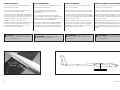
Allusive
™
2.2m
Instruction Manual
Bedienungsanleitung
Manuel d’utilisation
Manuale di Istruzioni

2
EFL Allusive 2.2m
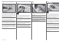
SAFETY WARNINGS AND PRECAUTIONS
Read and follow all instructions and safety precautions
before use. Improper use can result in fi re, serious injury
and damage to property.
Components
Use only with compatible components. Should any
compatibility questions exist, please refer to the product
instructions, component instructions or contact the
appropriate Horizon Hobby offi ce.
Flight
Fly only in open areas to ensure safety. It is
recommended fl ying be done at radio control fl ying
fi elds. Consult local ordinances before choosing a fl ying
location.
Propeller
Keep loose items that can become entangled in
the propeller away from the prop. This includes
loose clothing or other objects such as pencils and
screwdrivers. Keep your hands away from the propeller
as injury can occur.
Batteries
Always follow the manufacturer’s instructions when using
and disposing of any batteries. Mishandling of Li-Po
batteries can result in fi re causing serious injury and
damage.
Small Parts
This kit includes small parts and should not be left
unattended near children as choking and serious injury
could result.
SAFE OPERATING RECOMMENDATIONS
• Inspect your model before every fl ight to ensure it is
airworthy.
• Be aware of any other radio frequency user who may
present an interference problem.
• Always be courteous and respectful of other users in
your selected fl ight area.
• Choose an area clear of obstacles and large enough to
safely accomodate your fl ying activity.
• Make sure this area is clear of friends and spectators
prior to launching your aircraft.
• Be aware of other activities in the vicinity of your fl ight
path that could cause potential confl ict.
• Carefully plan your fl ight path prior to launch.
• Abide by any and all established AMA National Model
Aircraft Safety Code.
REGARDING MOTOR AND BATTERY
SELECTION
This model has been tested using the components
listed in the Power Systems section of this manual.
Using components that exceed the output of the listed
components may place excessive loads on the airframe.
This could result in the failure of the airframe in high-
speed or high-load situations.
NOTICE
All instructions, warranties and other collateral documents are subject to change at the sole discretion of Horizon
Hobby, Inc. For up-to-date product literature, visit horizonhobby. com and click on the support tab for this product.
Meaning of Special Language
The following terms are used throughout the product literature to indicate various levels of potential harm when
operating this product:
NOTICE: Procedures, which if not properly followed, create a possibility of physical property damage AND a little
or no possibility of injury.
CAUTION: Procedures, which if not properly followed, create the probability of physical property damage AND a
possibility of serious injury.
WARNING: Procedures, which if not properly followed, create the probability of property damage, collateral
damage, and serious injury OR create a high probability of superfi cial injury.
WARNING: Read the ENTIRE instruction manual to become familiar with the features of the product
before operating. Failure to operate the product correctly can result in damage to the product, personal
property and cause serious injury.
This is a sophisticated hobby product. It must be operated with caution and common sense and requires some
basic mechanical ability. Failure to operate this Product in a safe and responsible manner could result in injury
or damage to the product or other property. This product is not intended for use by children without direct adult
supervision. Do not use with incompatible components or alter this product in any way outside of the instructions
provided by Horizon Hobby, Inc. This manual contains instructions for safety, operation and maintenance. It is
essential to read and follow all the instructions and warnings in the manual, prior to assembly, setup or use, in
order to operate correctly and avoid damage or serious injury.
Age Recommendation: Not for children under 14 years. This is not a toy.
USING THE MANUAL
This manual is divided into sections to help make assembly easier to understand. Boxes () have been placed next
to each step. These help keep track of steps that have been completed.
Page is loading ...
Page is loading ...
Page is loading ...

6
EFL Allusive 2.2m
87.5 in (2.20m)
546 sq in (35.2 dm2)
43.0 in (1.10m)
48.0 oz (1.40 kg)
Electric Power Power: Power 15 Brushless
Elektro Antrieb Power: Power 15 Brushless
Moteur électrique (EP): Power 15 Brushless
Motore elettrico: Power 15 Brushless
4-channel (or greater) with 4 servos with
V-Tail mixing capability
4-Kanal (oder größer) mit 4 Servos
mit V-Leitwerksmischer
4 voies (ou plus) avec 4 servos avec
mixage pour empennage en V
a 4 canali (o più) con 4 servo e
con miscelazione per la coda a V
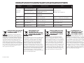
SPECIFICATIONS•SPEZIFIKATIONEN•
SPÉCIFICATIONS•SPECIFICHE
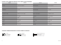
LARGE PARTS LAYOUT•BAUTEILE (OHNE KLEINTEILE)•GRANDES PIÈCES•SCHEMA DEI COMPONENTI GRANDI
ASSEMBLY SYMBOL GUIDE•MONTAGE SYMBOLE•GUIDE DES SYMBOLES POUR ASSEMBLAGE•GUIDA AI SIMBOLI DI ASSEMBLAGGIO
15
L
R
L
R
Use thin CA
Dünnfl üssigen
Sekundenkleber verwenden
Utilisez de la colle
cyanoacrylate fi ne
Usare colla ciano acrilica fi ne
Use a felt-tipped pen
Verwenden Sie einen Faserstift
Utilisez un feutre fi n effaçable
Usare un pennarello
Use 5-minute epoxy
Verwenden Sie 5 Minuten Epoxy
Utilisez de l’époxy 5 minutes
Usare una resina epossidica con
indurimento di 5 minuti
Ensure free rotation
Rotation sicherstellen
Permettez une rotation libre
Assicurarsi rotazione libera
Apply threadlock
Schraubensicherungslack verwenden
Utilisez du frein fi let
Applicare fuido threadlock
Assemble right and left
Links und rechts montieren
Assemblez à droite et à gauche
Assemblare destra e sinistra
Fully tighten
Vollständig festziehen/festschrauben
Serrez complètement
Stringere al massimo
Use hobby knife with
#11 blade
Verwenden Sie ein Hobbymesser mit
# 11 Klinge
Utilisez un Couteau: Lame numéro
11
Usare taglierino per hobbistica con
lama numero 11
1
2
5
6
7
5
5
5
6
4 4
3

7
EFL Allusive 2.2m
REPLACEMENT PARTS•ERSATZTEILE•PIÈCES DE RECHANGE•RICAMBI
Part English Deutsch Français Italiano
1. EFL492501 Right Wing Panel Tragfl äche rechts Aile droite Semiala destra
2. EFL492502 Left Wing Panel Tragfl äche links Aile gauche Semiala sinistra
3. EFL492503 Fuselage Rumpf Fuselage Fusoliera
4. EFL492504 Stabilizer Set Leitwerksset Stabilisateurs Set stabilizzatore
5. EFL492505 Hardware Pack Kleinteilepaket Sachet d’accessoires Viti e accessori
6. EFL492506 Wing Rod Set Flächenverbinder Set de clés d’aile Set baionette ala
7. EFL492507 Canopy Kabinenhaube Verrière Calotta
REQUIRED RADIO EQUIPMENT•ERFORDERLICHE RC AUSRÜSTUNG•EQUIPEMENT RADIO REQUIS•APPARECCHIATURE RADIO
SPMAR6260 AR6260 DSMX
®
6-Channel AR6260 DSMX® 6-Kanal Récepteur AR6260 6 voies DSMX AR6260 DSMX ricevitore 6 canali per
Carbon Fuselage Receiver Carbon Rumpf Empfänger pour fuselage carbone fusoliera in carbonio
SPMSA5030 (2) A5030 Mini Digital Aicraft Servo Spektrum A5030 Mini Digital Flug -Servo Mini-servo numérique A5030 pour aéronefs Servo digitale mini A5030 per aeromodelli
SPMSA7020 (2) A7020 Digital Wing Servo A7020 digitales Tragfl ächenservo Servo A7020 Digital pour aile A7020 servo digitale per ala
SPMA3051 (2) Standard Servo Extension, 6-inch Spektrum Servokabelverlängerung 150mm Rallonge servo standard, 150mm Prolunga standard per servo, 150mm
SPMA3004 (2) Standard Servo Extension, 18-inch Spektrum Servokabelverlängerung 460mm Rallonge servo standard, 460mm Prolunga standard per servo, 460mm
POWER SYSTEM•ANTRIEB•MOTORISATION•SISTEMA PROPULSIVO
EFLM4015A Power 15 Brushless Outrunner Motor, 950Kv Power 15 Brushless Außenläufer Motor, 950Kv Moteur Power 15 brushless à cage Power 15 motore brushless a cassa
tournante, 950Kv rotante, 950Kv
EFLA1040LB 40-Amp Lite Pro SB Brushless ESC (V2) 40A Lite Pro SB Brushless ESC (V2) Contrôleur brushless 40A Lite Pro (V2) 40-Amp Lite Pro SB Brushless ESC (V2)
EFLB22003S30 2200mAh 3S 11.1V 30C Li-Po 2200mAh 3S 11.1V 30C Li-Po Batterie Li-Po 3S 11.1V 2200mA 2200mAh 3S 11.1V 30C Li-Po
EFLP12080PP Plastic Propeller, 12 x 8 Kunststoff Propeller, 12 x 8 Hélice plastique 12x8 Elica in plastica, 12 x 8
EFLP12080S Spinner Assembly Spinner Cône + moyeu Gruppo ogiva
REQUIRED ADHESIVES•ERFORDERLICHE KLEBSTOFFE•TYPES DE COLLES•ADESIVI NECESSARI
PAAPT09 Thin CA Sekundenkleber dünnfl üssig Colle cyano fi ne Sottile CA
PAAPT35 15-Minute Epoxy 15 Minuten Epoxy Époxy 15 minutes Colla epoxy 15 minuti
OPTIONAL ITEMS•OPTIONALE TEILE•ELÉMENTS OPTIONNELS•ARTICOLI OPZIONALI
EFLP12080CP Carbon Propeller, 12 x 8 Carbon Propeller, 12 x 8 Hélice carbone 12x8 Elica in carbonio, 12 x 8
EFLA110 Power Meter E-fl ite Lastmessgerät Wattmètre Misuratore di potenza
EFLC3020 Celectra
™
200W DC Charger E-fl ite 200W DC Multi-Akku Ladegerät Chargeur CC 200W Celectra Celectra 200W DC Caricabatterie

8
EFL Allusive 2.2m
REQUIRED TOOLS•BENÖTIGTES WERKZEUG•OUTILS REQUIS•ATTREZZI NECESSARI
English Deutsch Français Italiano
Box wrench: 12mm Ringschlüssel: 12mm Clé plate fermée 12mm Chiave a tubo: 12mm
Clear tape Transparentes Klebeband Adhésif transparent Nastro trasparente
Drill bit: 1/16-inch, 5/64-inch Bohrer: 1,5 mm, 2mm Foret : 1,5 mm, 2mm Punte per trapano: 1,5 mm, 2mm
Electrical tape-white Isolierband weiss Ruban adhésif d’électricien blanc Nastro elettrico bianco
Felt-tipped pen Faserstift Feutre fi n effaçable Pennarello
Hemostat Klemme Pince Hemostat Pinzetta
Hex wrench: 1/16-inch Inbusschlüssel: 1/16-inch Tournevis hexagonal : 1/16-inch Chiave esag.: 1/16-inch
Hobby knife: #11 blade Hobbymesser mit # 11 Klinge Couteau : Lame numéro 11 Taglierino: #11 lama
Phillips screwdriver: #1 Phillips Schraubendreher: #1 Tournevis cruciforme: #1 Cacciavite a croce: #1
Pin vise Handbohrer Porte-forets Trapano manuale
Pliers Zange Pince Pinze
Ruler Lineal Réglet Righello
Sandpaper Schleifpapier Papier de verre Carta vetrata
Scissors Schere Ciseaux Forbici
Side cutters Seitenschneider Pince coupante Lama laterale
Toothpicks Zahnstocher Cure dents Stuzzicadenti
FASTENERS•VERBINDUNGSELEMENTE•ATTACHES•ELEMENTI DI FISSAGGIO
M
Hex Nut
Sechskantmutter
Ecrou hexagonal
Dado esagonale
Washer-Head Machine Screw
Breitkopf- Maschinenschraube
Vis à tête épaulée
Vite per metallo con rondella
Metal Clevis
Gabelkopf
Chape métallique
Forcella metallica

9
EFL Allusive 2.2m
BEFORE STARTING ASSEMBLY
• Remove parts from bag.
• Inspect fuselage, wing panels, rudder and stabilizer
for damage.
• If you fi nd damaged or missing parts, contact your
place of purchase.
If you fi nd any wrinkles in the covering, use a heat gun
(HAN100) and covering glove (HAN150) or covering iron
(HAN101) with a sealing iron sock (HAN141) to remove
them. Use caution while working around areas where the
colors overlap to prevent separating the colors.
This model has been designed to keep the weight at a
minimum. When tightening the covering, work carefully
to avoid inducing warps or changing the alignment of the
structure.
• Charge transmitter and receiver batteries.
• Center trims and sticks on your transmitter.
• For a computer radio, create a model memory for this
particular model.
• Bind your transmitter and receiver, using your radio
system’s instructions.
IMPORTANT: Rebind the radio system once all
control throws are set. This will keep the servos from
moving to their endpoints until the transmitter and
receiver connect. It will also guarantee the servo
reversal settings are saved in the radio system.
VOR DEM ZUSAMMENBAU
• Entnehmen Sie zur Überprüfung jedes Teil der
Verpackung.
• Überprüfen Sie den Rumpf, Tragfl ächen, Seiten- und
Höhenruder auf Beschädigung.
• Sollten Sie beschädigte oder fehlende Teile feststellen,
kontaktieren Sie bitte den Verkäufer.
Zum Entfernen von Falten in der Bespannung verwenden
Sie den Heißluftfön (HAN100) und Bespannhandschuh
(HAN150) oder das Folienbügeleisen (HAN141). Bitte
achten Sie bei überlappenden Farben, dass Sie diese sich
bei dem Bearbeitung nicht trennen.
Dieses Modell wurde auf geringstes Gewicht konstruiert.
Bitte beachten Sie bei dem Spannen der Bespannfolie,
dass sie nicht die Ausrichtung der Struktur verändern.
• Laden des Senders und Empfängers.
• Zentrieren der Trimmungen und Sticks auf dem
Sender.
• Sollten Sie einen Computersender verwenden,
resetten Sie einen Speicherplatz und benennen ihn
nach dem Modell.
• Sender und Empfänger jetzt nach den Bindeanweisung
des Herstellers zu binden.
WICHTIG: Wir empfehlen dringend nachdem alle
Einstellungen vorgenommen worden sind, das Modell
neu zu binden. Dieses verhindert, dass die Servos
in die Endanschläge laufen bevor sich Sender und
Empfänger verbunden haben. Es garantiert auch, dass die
Servoreverseeinstellungen in der RC Anlage gesichert sind.
AVANT DE COMMENCER
L’ASSEMBLAGE
• Retirez toutes les pièces des sachets pour les
inspecter.
• Inspectez soigneusement le fuselage, les ailes et les
empennages.
• Si un élément est endommagé, contactez votre
revendeur.
Si l’entoilage présente des plis, vous pouvez les
lisser en utilisant le pistolet à air chaud (HAN100)
et le gant (HAN150) ou le fer à entoiler (HAN101)
avec la chaussette de protection (HAN141). Agissez
soigneusement dans les zones où plusieurs couleurs
d’entoilage sont superposées afi n d’éviter de les séparer.
Ce modèle a été conçu pour obtenir une masse
minimale. Quand vous retendez l’entoilage, prenez soin
de ne pas déformer la structure.
• ll est recommandé de préparer tous les éléments du
système de la radio.
• Cela inclut, la charge des batteries comme la mise au
neutre des trims et des manches de votre émetteur.
• Si vous utilisez une radio programmable, sélectionnez
une mémoire libre afi n d’y enregistrer les paramètres
de ce modèle.
• Nous vous recommandons d’affecter maintenant le
récepteur à l’émetteur en suivant les instructions
fournies avec votre radio.
IMPORTANT: Il est hautement recommandé de
ré-affecter le système une fois que les courses seront
réglées. Cela empêchera les servos d’aller en butée lors
de la connexion du système. Cela garantit également que
la direction des servos est enregistrée dans l’émetteur.
PRIMA DI INIZIARE IL MONTAGGIO
• Togliere tutti i pezzi dalla scatola.
• Verifi care che la fusoliera, l’ala e i piani di coda non
siano danneggiati.
• Se si trovano parti danneggiate, contattare il negozio
da cui è stato acquistato.
Se si trovano delle pieghe nella ricopertura, si possono
togliere usando una pistola ad aria calda (HAN100) e
guanto per ricopertura (HAN150), oppure un ferro per
ricopertura (HAN101) con la sua calza di protezione
(HAN141). Usare cautela quando si lavora in aree del
rivestimento dove ci sono dei colori sovrapposti, per
evitare la loro separazione.
Questo modello è stato progettato per mantenere al
minimo il suo peso. Quando si tende il rivestimento,
bisogna lavorare con attenzione per non fare delle grinze
o modifi care l’allineamento delle strutture (svergolature).
• Caricare il trasmettitore e la batteria di volo.
• Centrare stick e trim sul trasmettitore.
• Con una radio computerizzata creare una nuova
memoria per questo modello.
• Facendo riferimento alle istruzioni del radiocomando,
connettere (bind) trasmettitore e ricevitore.
IMPORTANTE: Ripetere la procedura di connessione
una volta regolate le corse, per evitare che i servi vadano
a fi ne corsa. Garantirà anche che le impostazioni di
inversione del servo vengano salvate nel sistema radio.

10
EFL Allusive 2.2m
1
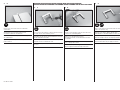
Aileron Control Horns•
Querruderhörner•Guignol des
ailerons•Squadrette per alettoni
Ruddervator Control Horns•
V-Leitwerkshörner•Guignols de
stabilisateurs•Squadrette per coda a V
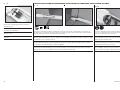
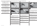
Locate the aileron and ruddervator control horn. Note
the ruddervator control horns do not have a hole where
the horn fi ts into the control surface.
Legen Sie die Querruder - und V-Leitwerkshörner
bereit. Bitte beachten Sie, dass die V-Leitwerkshörner
am Unterteil dass in die Tragfl äche gesteckt wird. kein
Loch haben.
Repérez les guignols d’ailerons et de stabilisateur. Vous
remarquerez que les guignols de stabilisateur n’ont pas
de trou au niveau de leur base.
Individuare le squadrette per alettoni e piani di coda a
V, notando che quelle per i piani di coda a V non hanno il
foro sulla parte che entra nella superfi cie di controllo.
2
L
R
L
R
Use sandpaper to lightly sand the bottom of the control
horn where it fi ts into the control surface. Remove any
dirt and oils from the control horn using a paper towel
and isopropyl alcohol.
Schleifen Sie den Teil des Ruderhorns an der
in das Ruder gesteckt wird. Entfernen Sie alle
Verschmutzungen vom Ruderhorn mit einem Papiertuch
und Reinigungsalkohol.
Utilisez du papier abrasif pour poncer la partie basse du
guignol qui entre dans la dérive. Retirez la poussière et
les traces de lubrifi ant en utilisant du papier absorbant
et de l’alcool dénaturé.
Carteggiare leggermente la parte inferiore delle
squadrette, proprio dove entrano nella superfi cie di
controllo. Pulirle da polvere ed olio usando un fazzoletto
di carta e alcool isopropilico.
3
L
R
L
R
Place low-tack tape so it is spaced 1/32 inch (1mm)
from the base of the control horn. This will prevent epoxy
from getting on the aileron surface when the control horn
is glued in place.
Kleben Sie Kreppband mit 1mm Abstand zum Ruderhorn
auf. Das verhindert dass Epoxy auf der Ruderfl äche klebt
wenn das Ruderhorn eingeklebt wird.
Placez de l’adhésif de masquage à une distance de 1mm
autour de la fente destinée au guignol. Cela permet
d’éviter de mettre de la colle sur la surface de l’aileron
quand le guignol est collé en place.
Mettere del nastro a bassa adesività in modo che sia
distanziato di 1mm dalla base della squadretta. Questo
serve ad evitare che la colla epoxy esca dalla superfi cie
di controllo quando si incolla la squadretta.
4
15
Mix a small amount of 15-minute epoxy. Use a toothpick
to apply epoxy in the slot for the control horn, and to the
area of the control horn that fi ts into the aileron. Fit the
control horn in the aileron. The horn will fi t snug in the
slot. Use a paper towel and isopropyl alcohol to remove
any excess epoxy from around the control horn. Before
the epoxy fully cures, remove the tape from around the
control horn.
Mischen Sie eine kleine Menge von 15 Minuten Epoxy
und geben den Klebstoff mit einem Zahnstocher in den
Schlitz und auf die Aufl agefl äche. Das Horn paßt saugend
in den Schlitz. Wischen Sie überschüssigen Kleber mit
einem Papiertuch und Reinigungsalkohol ab. Entfernen
Sie das Klebeband bevor der Klebstoff vollständig
getrocknet ist.
Mélangez une petite quantité de colle époxy 15 minutes.
Utilisez un cure-dent pour appliquer la colle Epoxy dans
la fente destinée à recevoir le guignol. Insérez le guignol
dans l’aileron. Le guignol doit être correctement ajusté.
Utilisez du papier absorbant et de l’alcool dénaturé pour
retirer l’excès de colle autour du guignol. Retirez l’adhésif
de masquage avant le séchage total de la colle époxy.
Miscelare una piccola quantità di colla epoxy 15 minuti.
Con uno stuzzicadenti applicarla nelle fessure per le
squadrette e sulla parte delle squadrette che entra
negli alettoni. Le squadrette si inseriscono precise
negli alettoni. Togliere gli eccessi di colla intorno
alle squadrette con un fazzoletto di carta e alcool
isopropilico. Prima che la colla sia asciutta, togliere il
nastro messo prima intorno alle squadrette.
CONTROL HORN INSTALLATION•EINBAU DER RUDERHÖRNER•INSTALLATION DES GUIGNOLS•INSTALLAZIONE DELLE SQUADRETTE

11
EFL Allusive 2.2m
5
15
Repeat steps 3 and 4 to install the ruddervator
control horns.
Wiederholen Sie die Schritte 3 und 4 um die
V-Leitwerksruderhörner zu montieren.
Répétez les étapes 3 et 4 pour installer les guignols
des stabilisateurs.
Ripetere i passi 3 e 4 per montare le squadrette dei
piani di coda a V.
1
L
R
L
R
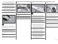
Use a pin vise and 1/16-inch (1.5mm) drill bit to enlarge
the holes for the servo mounting screws.
Vergrößern Sie mit einem 1,5mm Handbohrer die Löcher
für die Servoeinbauschrauben.
Utilisez un porte foret muni d’un foret de 1.5mm pour
agrandir les trous de fi xation du servo.
Forare con una punta da 1,5mm per le viti di fi ssaggio
dei servi.
2
L
R
L
R
Thread a servo mounting screw into each hole to cut
threads in the surrounding wood.
Drehen Sie in jede Bohrung eine Servo-
Befestigungsschraube, um ein Gewinde in das Holz
zu schneiden.
Visser une vis de fi xation de servo dans chaque trou pour
créer un fi letage dans le bois.
Avvitare una vite per il montaggio dei servo in ciascun
foro per eseguire dei fi letti nel legno circostante.
3
L
R
L
R
Apply a small amount of thin CA to harden the threads
made in the previous step.
Geben Sie einen kleinen Tropfen dünnfl üssigen
Sekundenkleber in die Gewindelöcher um diese zu härten.
Appliquer une petite quantité de colle cyano fi ne pour
durcir les fi letages faits lors de l’étape précédente.
Mettere una piccola quantità di colla CA nei fori, per
indurire il fi letto fatto nel passaggio precedente.
AILERON SERVO INSTALLATION•EINBAU DER QUERRUDERSERVOS•
INSTALLATION DES SERVOS D’AILERONS•INSTALLAZIONE SERVO DELL’ALETTONE
Page is loading ...

13
EFL Allusive 2.2m
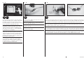
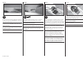
7
L
R
L
R
Tie the string located inside the wing around the end
of the servo extension. Wrap a piece of low-tack tape
around the end, and form it into a point. This will guide
the end of the extension easily through the wing.
Knoten Sie die Schnur aus der Tragfläche um die
Servoverlängerung. Wickeln Sie etwas Kreppband
um das Ende und formen es zu einer Spitze. Das
hilft dabei das Ende der Verlängerung durch die
Tragfläche zu führen.
Nouez la fi celle située dans l’aile autour de la rallonge
de servo, entourez l’extrémité de la rallonge d’adhésif de
masquage. Cela vous permettra de glisser facilement la
rallonge dans l’aile.
Legare lo spago collocato all’interno dell’ala al connettore
della prolunga. Avvolgere del nastro a bassa adesività
per arrotondare il terminale e poterlo far scorrere
meglio all’interno dell’ala.
10
L
R
L
R
x2
M2
x2
M
Use a 1
1
/
2
-inch (38mm) pushrod and the hardware listed
to assemble the aileron linkage. Adjust the clevis so the
aileron is centered when the servo is centered using the
radio system. Slide the retainer over the forks of the
clevis to secure it to the control horn. Tighten the nut
against the clevis.
Montieren Sie die Anlenkung mit dem 38mm langen
Gestänge. Justieren Sie den Gabelkopf so, dass das
Querruder mit zentriertem Servo ebenfalls zentriert ist.
Schieben Sie das Sicherungsgummi über die Gabeln und
drehen die Mutter fest.
Utilisez la tringlerie de 38mm et les accessoires listés
pour assembler la commande de l’aileron. Réglez la
chape de façon à centrer l’aileron quand le servo est au
neutre. Glissez le morceau de durite sur les fourches de
la chape pour sécuriser la liaison. Serrez l’écrou contre
la chape.
Usare un rinvio da 38mm con le sue forcelle per
collegare il servo all’alettone. Regolare la forcella in
modo che l’alettone sia centrato quando il servo viene
centrato con il radiocomando. Far scorrere il fermo sulla
forcella per bloccarla sulla squadretta. Stringere il dado
contro la forcella.
11
L
R
L
R
Use hobby scissors to trim the aileron servo cover.
The cover is attached to the wing using clear tape.
Make sure the cover is trimmed and positioned so the
linkage does not bind on the cover when the aileron
servo is in operation.
Schneiden Sie mit einer Hobbyschere die
Querruderservoabdeckung zurecht und kleben diese
mit klarem Klebeband fest. Bitte stellen Sie sicher,
dass die Abdeckung korrekt positioniert ist und das
Querruderservo im Betrieb nicht behindert.
Utilisez des ciseaux à Lexan pour découper le carénage
de servo d’aileron. Le carénage se fi xe sur l’aile à l’aide
de ruban adhésif transparent. Contrôlez que le carénage
est correctement découpé et ajusté autour du passage
de la tringlerie afi n d’éviter tout risque de blocage durant
le fonctionnement du servo.
Rifi lare il coperchio del servo alettoni con forbici da
hobby e fi ssarlo all’ala con nastro adesivo trasparente.
Verifi care che nel movimento del servo non ci siano
attriti con il coperchio.
8
L
R
L
R
Use the string to pull the extension through the wing.
The tape can be removed once the extension is through
the wing.
Ziehen Sie mit der Schnur die Verlängerung durch
die Tragfl äche. Danach können Sie das Kreppband
wieder abnehmen.
Tirez sur la fi celle pour tirer la rallonge à travers l’aile.
Retirez l’adhésif de masquage une fois que la rallonge
est sortie de l’aile.
Usare lo spago per tirare la prolunga attraverso l’ala.
Fatto questo si può togliere il nastro adesivo.
9
L
R
L
R
Secure the servo in the mount using the screws provided
with the servo.
Schrauben Sie das Servo mit den Schrauben aus dem
Lieferumfang fest.
Fixez le servo au support en utilisant les vis fournies
avec le servo.
Fissare il servo sul supporto usando le sue viti.

14
EFL Allusive 2.2m
1
L
R
L
R
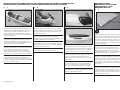
Slide the two stabilizer pins into the stabilizer sockets.
Schieben Sie die beiden Leitwerksstifte in das Leitwerk.
Glissez les 2 clés dans les fourreaux des stabilisateurs.
Inserire le due baionette dello stabilizzatore nelle
loro sedi.
2
L
R
L
R
Fit the stabilizer to the fuselage with the control horn
facing the top of the fuselage.
Schieben Sie das Leitwerk in den Rumpf. Die
Ruderhörner zeigen dabei nach oben.
Glissez le stabilisateur dans le fuselage, le guignol doit
être orienté vers le dessus du fuselage.
Allineare uno stabilizzatore alla fusoliera con la
squadretta rivolta verso l’alto.
3
15
Fit the remaining stabilizer to the fuselage. Once fi t, remove the stabilizers and pins. Apply a small amount of epoxy
on the pins and into the holes in the stabilizers. Place the pins in the stabilizers. Place a small amount of epoxy in
the holes in the fuselage, then reposition the stabilizers so they fi t tightly against the fuselage. Use a small piece of
low-tack tape to hold the stabilizers against the fuselage until the epoxy fully cures. Use a paper towel and isopropyl
alcohol to remove any excess epoxy before it cures.
Setzen Sie die zweite Leitwerkshälfte in den Rumpf. Ist diese ausgerichtet nehmen Sie beide heraus. Geben Sie eine
kleine Epoxy Menge auf die Stifte und in die Öffnungen im Leitwerk. Setzen Sie die Stifte in das Leitwerk. Geben Sie
eine kleine Menge Epoxy in die Löcher im Rumpf und passen dann das Leitwerk an den Rumpf an, so dass es sauber
am Rumpf ansitzt. Sichern Sie das Leitwerk mit Kreppband bis der Klebstoff vollständig ausgehärtet ist. Wischen Sie
überschüssigen Klebstoff mit einem Papiertuch und Isopropylalkhohol weg bevor der Kleber getrocknet ist.
Glissez le deuxième stabilisateur dans le fuselage. Retirez les deux stabilisateurs. Appliquez de la colle époxy dans
les fourreaux des stabilisateurs pour coller les clés. Appliquez de la colle époxy dans les trous du fuselage, puis
repositionnez les stabilisateurs sur le fuselage, ils doivent être parfaitement plaqués contre le fuselage. Utilisez de
l’adhésif de masquage pour maintenir les stabilisateurs en position durant le séchage de la colle époxy.
Allineare anche l’altro stabilizzatore alla fusoliera. Fatto questo togliere gli stabilizzatori e le loro baionette. Mettere
un po’ di colla epoxy sulla baionetta e nella sua sede sullo stabilizzatore e poi riposizionare il tutto allineandolo alla
fusoliera. Usare un pezzettino di nastro a bassa adesività per tenere lo stabilizzatore contro la fusoliera intanto che la
colla si asciuga. Con un fazzoletto di carta e alcool isopropilico togliere gli eccessi di colla prima che si indurisca.
STABILIZER INSTALLATION•MONTAGE DES HÖHENRUDERS•
INSTALLATION DU STABILISATEUR•INSTALLAZIONE DELLO STABILIZZATORE

15
EFL Allusive 2.2m
1
Use the radio system to center the ruddervator servos.
Install the servo arm on the servo, trimming it so it won’t
interfere with the side of the fuselage when installed. The
linkage will connect to the hole of the arm that is 5/16
inch (8mm) from the center of the servo.
Zentrieren Sie das Leitwerk mit der Fernsteuerung .
Setzen Sie den Arm auf das Servo auf und schneiden den
Arm so zurecht, dass er im Rumpf ohne Behinderung
laufen kann. Das Gestänge wird an das Loch
angeschlossen dass 8mm von der Mitte entfernt ist.
Utilisez la radio pour placer les servos au neutre. La
tringlerie sera reliée au trou situé à une distance de
8mm du centre. Coupez le bras de servo de manière qu’il
ne frotte pas le côté du fuselage durant son mouvement.
Usare il radiocomando per centrare i servi dei piani di
coda a V. Montare le squadrette sui servi tagliandole
quanto basta in modo che non tocchino la fi ancata della
fusoliera. Il rinvio si collega al foro che sta a 8mm dal
centro della squadretta.
3
Use a pin vise and a 1/16-inch (1.5mm) drill bit to drill
the holes for the servo mounting screws through the
mounting plate.
Bohren Sie mit einem 1,5mm Bohrer die Löcher für die
Servoschrauben durch die Montageplatte.
Utilisez un porte foret muni d’un foret de 1.5mm pour
percer les trous de fi xation des servos dans la platine.
Con una punta da 1,5mm praticare sul sopporto i fori
per le viti di fi ssaggio del servo.
4
Thread a servo mounting screw into each hole to cut
threads in the surrounding wood. Apply a small amount
of thin CA to harden the threads made by the screws.
Secure the servo in the fuselage using the screws
provided with the servo. The output shaft of the servo
faces toward the rear of the fuselage.
Drehen Sie eine Servobefestigungsschraube in jedes
Loch um ein Gewinde zu schneiden. Geben Sie dann
einen Tropfen dünnfl üssigen Sekundenkleber in das
Loch um das Gewinde zu härten. Schrauben Sie dann
das Servo mit den Schrauben aus dem Lieferumfang
fest. Der Abtrieb des Servos zeigt dabei nach hinten
zum Heck des Flugzeuges.
Visser une vis de fi xation de servo dans chacun des
trous. Redevisser les vis et appliquez une goutte de colle
CA pour durcir les fi lets. Fixez le servo dans le fuselage
en utilisant les vis fournies avec le servo. La tête du
servo doit être orientée vers l’arrière du fuselage.
Avvitare una vite in ciascun foro e poi, dopo averla tolta,
mettere un po’ di colla CA per indurire la fi lettatura
fatta nel legno. Fissare il servo in fusoliera usando le
sue viti. L’albero di uscita del servo deve essere rivolto
verso la coda.
2
Place the servo in the fuselage with the servo output
facing the rear of the fuselage. Slide the servo as far
to the side as possible, then mark the locations for the
servo mounting screws.
Setzen Sie das Servo in den Rumpf mit dem Abtrieb nach
hinten ein. Schieben Sie das Servo so weit wie möglich
nach rechts und markieren dann die Schraublöcher für
die Servoschrauben.
Placez le servo dans le fuselage, la tête du servo doit
être orientée vers l’arrière du fuselage. Glissez le servo
au maximum possible sur le côté, puis marquez les
emplacements des vis de fi xation.
Mettere il servo nella fusoliera con l’albero di uscita
rivolto verso la coda e il più distante possibile dalla
fi ancata. Poi segnare la posizione delle viti di fi ssaggio.
SERVO INSTALLATION•SERVOEINBAU•INSTALLATION DES SERVOS•INSTALLAZIONE SERVO

16
EFL Allusive 2.2m
5
Repeat steps 1 through 4 to install the remaining
ruddervator servo.
Wiederholen Sie die Schritte 1 bis 4 um das zweite
V-Leitwerksservo einzubauen.
Répétez les étapes de 1 à 4 pour installer le
deuxième servo.
Ripetere i passi da 1 a 4 per montare l’altro servo
della coda.
2
L
R
L
R
Center the ruddervator control surface and ruddervator
servo. Use a felt-tipped pen to mark the pushrod where
it crosses the outer hole of the servo arm.
Zentrieren Sie die beiden V-Leitwerksservos. Markieren
Sie das Gestänge mit einem Faserstift dort wo das
äußere Loch den Servoarm kreuzt.
Placez les gouvernes et les servos au neutre. Utilisez
un feutre pour effectuer une marque sur la tringlerie à
l’emplacement du trou du bras de servo.
Centrare le superfi ci di controllo della coda e i servi
ad esse collegati. Segnare le barrette nel punto in cui
incrociano il foro esterno della squadretta del servo.
1
x2
M2
x2
M
Prepare the ruddervator pushrods by threading the nut and clevis on the brass fi tting. Make sure the threads of
the fi tting can be seen between the forks of the clevis. Slide the pushrods into the pushrod tubes located inside the
fuselage. Connect the clevises to the ruddervator control horns.
Bereiten Sie das Gestänge durch aufdrehen das Gabelkopfes und der Mutter vor. Bitte achten Sie darauf, dass das
Gewinde zwischen den Gabeln zu sehen ist. Schieben Sie das Gestänge in die Röhrchen im Rumpf. Schließen Sie dann
die Gabelköpfe an die V-Leitwerksruder an.
Préparez les tringleries en vissant les chapes et les écrous sur l’embout en laiton. Vissez les chapes, l’extrémité de
l’embout fi leté doit tangenter le point de jonction des fourches de la chape. Glissez les tringleries dans les gaines
situées dans le fuselage. Connectez les chapes aux guignols.
Preparare le barrette di rinvio per i comandi di coda avvitando i dadi e le forcelle sugli adattatori di ottone. Verifi care
che la parte fi lettata dell’adattatore si veda in mezzo alle forcelle. Inserire le barrette dei comandi nei loro tubetti
guida già montati in fusoliera. Collegare le forcelle alle squadrette dei piani di coda.
LINKAGE INSTALLATION•GESTÄNGEEINBAU•INSTALLATION DES TRINGLERIES•INSTALLAZIONE DEI RINVII

17
EFL Allusive 2.2m
3
L
R
L
R
Disconnect the clevis from the ruddervator control horn.
Use pliers to bend the pushrod 90 degrees at the mark
made in the previous step.
Trennen Sie den Gabelkopf vom Ruderhorn und biegen
den Draht mit einer Zange 90° nach oben wo er das
äußere Loch kreutzt.
Déconnectez les chapes des guignols. Utilisez une pince
pour couder la tringlerie à 90° au niveau de la marque
précédemment tracée.
Scollegare le forcelle dalle squadrette della coda. Piegare
la barretta a 90° con una pinza nel punto segnato prima.
4
L
R
L
R
x2
Remove the servo arm from the servo. Use a pushrod
connector to attach the pushrod to the servo arm.
Nehmen Sie den Servoarm vom Servo ab und setzen den
Sicherungsclip auf den Servoarm.
Retirez le bras du servo. Utilisez un connecteur pour
assurer la liaison de la tringlerie au bras de servo.
Togliere la squadretta dal servo. Poi collegarle la
barretta usando un apposito sistema di fi ssaggio
(vedi fi gura).
6
Repeat steps 2 through 5 to connect the second
ruddervator to the ruddervator servo.
Wiederholen Sie die Schritte 2 bis 5 um das zweite
Leitwerksservo anzuschließen.
Répétez les étapes de 2 à 5 pour installer la commande
de la deuxième gouverne.
Per l’altro semielevatore, ripetere i passi da 2 a 5.
5
L
R
L
R
With the servo centered, reinstall the servo arm. Use the
screw provided with the servo to secure the arm to the
servo. Check to make sure the portion of the pushrod above
the connector does not rub against the side of the fuselage.
If it does, use side cutters to trim the excess wire.
Setzen Sie den Arm auf das zentrierte Servo wieder
auf und sichern diesen mit der Schraube aus dem
Lieferumfang. Bitte prüfen Sie dass der Draht nicht
am Rumpf scheuert, falls doch kürzen Sie ihn mit
einem Seitenschneider.
En ayant le servo au neutre, replacez le bras de servo
sur le servo. Utilisez la vis fournie avec le servo.
Contrôlez que l’extrémité coudée de la tringlerie
n’entre pas en contact avec le fl anc du fuselage. Si
c’est le cas, utilisez une pince coupante pour couper
la longueur excédante.
Con il servo centrato, rimettere le squadrette fi ssandole
con la loro vite. Verifi care che la porzione di barretta
al di sopra del connettore non strisci contro la fi ancata
della fusoliera. Se si dovesse verifi care questo problema,
con un tronchesino tagliare la barretta in eccesso.

18
EFL Allusive 2.2m
7
L
R
L
R
With the radio system on and servo centered, adjust
the clevises so the ruddervators are centered. Once the
linkage length has been set, tighten the nuts against the
clevises to prevent them from vibrating loose.
Justieren Sie mit zentrierter Fernsteuerung die
Gabelköpfe so, dass die Ruder zentriert sind. Drehen Sie
nach der Einstellung die Muttern gegen die Gabelköpfe
damit diese sich nicht lösen können.
En utilisant votre radio pour placer les servos au
neutre, réglez les chapes pour centrer les gouvernes.
Une fois que le réglage de longueur est effectué, serrez
l’écrou contre la chape pour éviter son desserrage par
les vibrations.
Con il radiocomando centrare i servi e regolare il
centraggio dei piani di coda agendo sulle forcelle. Una
volta regolate le barrette di comando, stringere i dadi
contro le forcelle per evitare che si allentino a causa
delle vibrazioni.
2
x4
M3 x 12
Fit the motor in the fuselage. Take your time to align the
mounting holes in the motor with those in the mount at
the front of the fuselage. Use the four screws listed to
secure the motor in the fuselage.
Passen Sie den Motor in den Rumpf ein. Bitte nehmen
Sie sich Zeit um die Schraublöcher mit den Löchern der
Motorbefestigung auszurichten.
Verwenden Sie die vier gelisteten Schrauben um den
Motor zu befestigen.
Sistemare il motore nella fusoliera avendo cura di
allineare bene i fori del motore con quelli del supporto
fi ssato alla fusoliera. Usare le 4 viti indicare per
fi ssare il motore.
3
Connect the leads from the speed control to those from
the motor. Cut a piece of hook and loop tape the length
of the speed control. Place the loop portion of the tape
on the bottom of the speed control. Place the hook
portion of the tape in the fuselage to secure the speed
control. Route the wiring for the motor so it will not
interfere with the operation of the motor.
Schließen Sie die Kabel vom Regler an den Motor an.
Schneiden Sie ein Stück Klettband auf der Länge des
Reglers zurecht. Kleben Sie die Hakenseite in den Rumpf,
die Klettseite an den Regler. Führen Sie die Motorkabel
so, dass Sie den Motorbetrieb nicht stören.
Connectez les câbles du contrôleur aux câbles du
moteur. Coupez un morceau de bande auto-agrippante
de la longueur du contrôleur. Placez la partie douce de
la bande auto-agrippante sous le contrôleur et placez la
partie dure dans le fuselage pour maintenir le contrôleur.
Guidez les câbles du moteur de façon qu’ils n’interfèrent
pas dans son fonctionnement.
Collegare i cavi del regolatore di velocità con quelli del
motore. Tagliare un pezzo di nastro a strappo che abbia
la lunghezza del regolatore e applicarne una parte ad
esso per fi ssarlo, applicando l’altra parte alla fusoliera.
Sistemare bene i cavi in modo che non vadano a
interferire con la rotazione del motore.
1
Use the instructions to reverse the motor shaft so it
can be attached to the propeller. Make sure to use
threadlock when installing the setscrews.
Reversieren Sie die Motorwelle nach Anleitung
so dass der Propeller montiert werden kann.
Verwenden Sie bei der Montage der Madenschrauben
Schraubensicherungslack.
Consultez la notice de votre moteur pour inverser la
sortie de l’axe moteur. N’oubliez pas le frein fi let quand
vous replacez les vis sans tête.
Seguire le istruzioni per invertire l’albero motore in modo
da poterlo collegare all’elica. Usare del frenafi letti per
bloccare i grani.
EP MOTOR INSTALLATION•E-MOTOR EINBAU•INSTALLATION DU MOTEUR EP•INSTALLAZIONE DEL MOTORE ELETTRICO

19
EFL Allusive 2.2m
Î The following shows the installation of
the EFLP12080PP (Plastic Propeller, 12 x
8) or EFLP12080CP (Carbon Propeller, 12
x 8) and EFLP12080S (Spinner Assembly).
These items must be purchased separately
as they are not included with the model.
Î Die folgenden Abbildungen zeigen die
Montage des EFLP12080PP (Kunststoff Propeller,
12 x 8) oder EFLP12080CP (Carbon Propeller,
12 x 8) und EFLP12080S (Spinner). Dieser
gehört nicht zum Lieferumfang des Modells
und muss separat erworben werden.
Î Les instructions suivantes montrent l’installation
de la référence EFLP12080PP (Hélice plastique
12x8) ou de la référence EFLP12080CP (Hélice
carbone 12x8) et de la référence EFLP12080S (Cône
avec moyeu). Ces éléments ne sont pas fournis
avec le modèle, ils sont vendus séparément.
Î Di seguito viene indicata l’installazione
dell’articolo EFLP12080PP (elica in plastica,
12 x 8) o EFLP12080CP (elica in carbonio,
12 x 8) e EFLP12080S (gruppo ogiva). Questi
articoli non sono inclusi nella confezione del
modello e sono da acquistare separatamente.
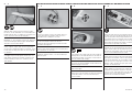
2
Once the blades fi t the yoke, use the pins and clips to
secure the blades to the yoke. Make sure the front of the
blades are facing toward the side of the yoke that has
the notch as shown in the previous step.
Passen die Blätter in das Zentralstück sichern Sie
diese mit den Pins und Clips. Stellen Sie bitte sicher,
dass die Vorderseite zu der Markierung aus dem
letzten Schritt zeigt.
Installez les pales sur le moyeu à l’aide des axes et
des clips. La face avant des pales doit être orientée du
côté des rainures (fl èches noires sur photo de l’étape
précédente) du moyeu.
Quando le pale sono ben adattate al supporto, fi ssarle
con i perni e le clips. Verifi care che la parte anteriore
delle pale sia rivolta verso il lato del supporto che ha la
tacca (vedi fi gura precedente).
3
Slide the yoke over the tapered spinner adapter. The
assembly can then be placed on the motor shaft. Thread
the nut on the adapter. Check that the yoke can rotate
freely and not contact the front of the fuselage during
its operation. Use a 12mm wrench to tighten the nut,
securing the yoke and adapter.
Schieben Sie den Propelleradapter über den Mitnehmer
und dann auf die Motorwelle. Drehen Sie eine Mutter
auf den Adapter. Überprüfen Sie ob der Mitnehmer frei
drehen kann und den Rumpf während des Betriebes
nicht berührt. Ziehen Sie die Schraube mit einem 12
Ringschlüssel fest.
Glissez le moyeu sur l’adaptateur et placez l’ensemble sur
l’axe du moteur. Contrôlez que le moyeu tourne librement
et qu’il n’entre pas en contact avec l’avant du fuselage
lors de sa rotation. Utilisez une clé de 12mm pour serrer
l’écrou afi n de sécuriser l’adaptateur et le moyeu.
Inserire il mozzo sull’adattatore conico e poi tutto
l’insieme sull’albero del motore. Avvitare il dado
sull’adattatore stringendolo con una chiave da 12mm
e accertandosi che il mozzo dell’elica possa girare
liberamente senza toccare la fusoliera.
1
Check the fi t of the propeller blades to the yoke. The
blade will move freely when the pin is installed. If not,
lightly sand the blades where they contact the yoke to
allow free movement.
Prüfen Sie die Passung des Propellers im Zentralstück.
Das Blatt sollte sich bei eingesetztem Stift frei
bewegen können. Falls nicht, schleifen Sie das Blatt
vorsichtig an den Kontaktstellen ab um eine freie
Bewegung zu ermöglichen.
Contrôlez l’ajustement des pales sur le moyeu. L’hélice
doit pouvoir pivoter librement quand l’axe est installé. Si
ce n’est pas le cas, poncez légèrement les pales au point
de contact avec le moyeu pour libérer le mouvement.
Verifi care che le pale dell’elica entrino perfettamente nel
supporto e che si possano muovere liberamente quando si
infi la il perno. In caso contrario carteggiare leggermente le
pale per farle entrare più facilmente nel supporto.
PROPELLER INSTALLATION•MONTAGE DES PROPELLERS•INSTALLATION DE L’HÉLICE•INSTALLAZIONE DELL’ELICA

20
EFL Allusive 2.2m
Î Use extreme caution around the propeller,
and check transmitter switch and throttle stick
positions before connecting the motor battery.
Î Sein Sie bitte extrem aufmerksam und
vorsichtig im Umgang mit dem Propeller.
Prüfen Sie die Position von Schaltern und dem
Gashebel bevor Sie den Akku anschließen.
Î Soyez très prudent autour de l’hélice et
contrôlez l’interrupteur et la position du manche
des gaz avant de connecter la batterie.
Î Usare estrema attenzione quando si lavora
attorno all’elica, e verificare la posizione del comando
motore prima di collegare la sua batteria.
4
Install the spinner, making sure it fi ts into the notches
in the propeller yoke. Use the screw provided with the
spinner and a #1 Phillips screwdriver to secure the
spinner to the adapter.
Montieren Sie den Spinner und achten bitte darauf dass
der Spinner korrekt auf dem Mitnehmer sitzt.
Installez le cône, prenez soin de bien le caler dans les
encoches du moyeu. Utilisez la vis fournie avec le cône
ainsi qu’un tournevis cruciforme #1 pour fi xer le cône à
l’adaptateur.
Montare l’ogiva accertandosi che si adatti bene al mozzo
e fi ssandola con la sua vite per mezzo di un cacciavite a
stella #1.
2
L
R
L
R
Route the 6-inch (150mm) servo leads through the
rectangular openings in the side of the fuselage.
Führen Sie die 150mm langen Servoakabel durch die
quadratischen Öffnungen auf der Rumpfseite.
Guidez une rallonge de 150mm par l’ouverture
rectangulaire située sur le côté du fuselage.
Far passare il cavo del servo da 150mm attraverso
l’apertura rettangolare sul fi anco della fusoliera.
Î Use a paper towel and isopropyl alcohol to
clean the area for the remote receiver before
installing it in the fuselage. This will remove
any debris or oils that may interfere with
the adhesion of the hook and loop tape.
Î Reinigen Sie die Klebefläche des
Satellitenempfängers mit einem Papiertuch
und Reinigungsalkohol bevor Sie ihn einkleben.
Das verhindert dass Verschmutzungen die
Haltekraft des Klettband beeinflussen.
Î Utilisez du papier absorbant et de l’alcool
dénaturé pour nettoyer la zone de fixation du
récepteur satellite. Cela permet d’assurer le
collage optimal de la bande auto-agrippante.
Î Per avere una adesione perfetta,
usare un fazzoletto di carta con alcool per
pulire l’area del ricevitore satellite su cui
andrà incollato il nastro a strappo.
3
Use hook and loop tape to attach the remote receiver
inside the fuselage. Make sure the receiver is back
far enough to allow clearance for the canopy mounting
retainer when the canopy is installed.
Befestigen Sie die Satellitenempfänger mit Klettband
im Rumpf. Bitte achten Sie darauf dass der Empfänger
weit genug nach hinten befestigt wird um den
Kabinenhaubenverschluss nicht zu behindern.
Utilisez de la bande auto-agrippante pour fi xer le
récepteur satellite dans le fuselage. Le récepteur
doit être suffi samment en arrière pour permettre
l’installation de la bulle et de sa languette de fi xation.
Sempre con nastro a strappo attaccare il ricevitore
satellite all’interno della fusoliera. Accertarsi che il
ricevitore sia abbastanza indietro per lasciare spazio
al montaggio del fermo per la capottina, quando si
dovrà fare.
1
Connect the leads and extensions to the receiver.
Schließen Sie die Kabel und die Verlängerungen an den
Empfänger an.
Connectez les fi ls et les rallonges au récepteur.
Collegare i cavi e le prolunghe al ricevitore.
RECEIVER INSTALLATION•EMPFÄNGEREINBAU•INSTALLATION DU RÉCEPTEUR•INSTALLAZIONE DEL RICEVITORE

21
EFL Allusive 2.2m
1
Using the remaining hook and loop tape and attach the
loop portion to the bottom of the battery. Do not cover
safety warnings with hook and loop tape. Place the
battery in the fuselage. The hook and loop strap goes
through the plastic fi tting, then loops back over the strap
to secure the battery.
Kleben Sie das verbleibene Klettband mit der Hakenseite
in den Rumpf und das Gegenstück auf die Unterseite
des Akkus. Überkleben Sie keine Warnhinweise. Die
Klettschlaufe wird durch die Kunststoffhalter geführt und
dann oben auf dem Akku zusammengeführt.
Utilisez la partie restante de bande auto-agrippante,
attachez sa partie douce sous la batterie. Ne recouvrez
pas les étiquettes de sécurité avec la bande auto-
agrippante. Glissez la batterie dans le fuselage. Les
sangles auto-agrippantes passent à travers la platine,
puis repassent sur la batterie pour assurer sa fi xation.
Usando il rimanente nastro a strappo, applicarne una
parte alla batteria. Non coprire le avvertenze per la
sicurezza. Mettere la batteria nella fusoliera. La fascetta
a strappo si avvolge intorno alla batteria comprendendo
anche il suo supporto in plastica.
2
Place the canopy on the fuselage. The tab at the front
of the canopy will fi t under the lip of the canopy opening.
Slide the canopy forward until the tab clears the lip at
the rear of the opening.
Setzen Sie die Kabinenhaube auf dem Rumpf. Der Stift
unter der Vorderkante der Haube passt unter den
vorderen Rumpfausschnitt. Schieben Sie die Kabinenhaube
zum Öffnen nach hinten bis der Stift frei ist.
Placez la bulle sur le fuselage. La languette située à
l’avant de la bulle se glisse sous le rebord de l’ouverture
du fuselage. Glissez la bulle vers l’avant pour dégager le
passage de la languette arrière.
Mettere la capottina sulla fusoliera, facendo in modo che
i riferimenti combacino e spingerla in avanti.
3
Place the tab at the rear of the canopy under the lip of
the canopy opening. You may need to press it downward
with your fi nger to fi t it under the lip. Slide the canopy
back until it fi ts into the recesses of the fuselage.
Setzen Sie den Stift am hinteren Kabinenhaubenende
an. Es kann notwendig sein, dass Sie ihm mit dem
Finger unter die Kante herunterdrücken müssen.
Schieben Sie die Kabinenhaube zurück bis diese in den
Rumpf einpasst.
Glissez la languette arrière sous le rebord de l’ouverture.
Vous devrez appuyer dessus avec votre doigt pour la
passer sous le rebord. Glissez la bulle en arrière pour
placer dans son empreinte moulée dans le fuselage.
Mettere la linguetta sul retro della capottina sotto al
labbro dell’apertura spingendola leggermente. Poi tirarla
indietro fi no all’incavo della fusoliera.
WING INSTALLATION•
MONTAGE DER TRAGFLÄCHEN•
INSTALLATION DE L’AILE•
MONTAGGIO DELL’ALA
1
15
Apply a small amount of epoxy to the fi rst 1/4 inch
(6mm) of the anti-rotation pins. Apply a small amount of
epoxy in the holes at the root of the wing where the pins
will fi t into the wing. Place both pins into their respective
holes. Use a paper towel and isopropyl alcohol to remove
any excess epoxy before it cures. Allow the epoxy to fully
cure before proceeding.
Geben Sie eine kleine Menge von Epoxy auf die ersten
6mm der Verdrehsicherungen und etwas in die
Löcher. Setzen Sie dann die Stifte ein und wischen
überschüssigen Klebstoff mit einem Papiertuch
und Reinigungsalkohol ab. Lassen Sie den Klebstoff
vollständig trocknen bevor Sie weitermachen.
Appliquez de la colle époxy sur une longueur de 6mm
des tétons anti-rotation. Appliquez une petite quantité
de colle dans les trous de l’emplanture de l’aile où les
tétons seront emboîtés. Placez les 2 tétons dans leurs
trous respectifs. Utilisez du papier absorbant et de
l’alcool dénaturé pour retirer l’excès de colle époxy avant
son séchage.
Applicare una piccola quantità di colla epoxy sui primi
6mm dei perni anti rotazione e all’interno dei fori che
si trovano alla radice dell’ala. Pulire gli eccessi di colla,
prima che asciughi, con un fazzoletto di carta e alcool
isopropilico. Prima di procedere attendere che la colla
sia completamente asciutta.
MOTOR BATTERY AND CANOPY INSTALLATION•EINSETZEN DES AKKUS UND DER KABINENHAUBE•
INSTALLATION DE LA BATTERIE ET DE LA BULLE•INSTALLAZIONE BATTERIA E CAPOTTINA

22
EFL Allusive 2.2m
2
Slide the wing tube into the wing tube socket.
Schieben Sie den Flächenverbinder in die Öffnung an
der Tragfl äche.
Faire glisser la clé d’aile dans le réceptacle du tube
de l’aile.
Inserire il tubo nella sua sede nell’ala.
3
Slide the wing panel into position, guiding the extensions
from the wing into the fuselage.
Schieben Sie die Tragfl äche in die richtige Position.
Führen Sie dabei die Verlängerungen vom Flügel in
den Rumpf.
Mettre en place le panneau de l’aile en le faisant glisser
et en veillant à guider les rallonges provenant de l’aile
dans le fuselage.
Far scorrere in posizione la semiala, guidando le
prolunghe dall’ala all’interno della fusoliera.
4
Once the wing is tight against the fuselage, use white
electrical tape along the joint between the wing and
fuselage. This will hold the wing in position. Place tape on
both the top and bottom of the wing.
Liegt die Fläche sauber am Rumpf an sichern Sie die
Fläche mit einem Streifen Klebeband auf der Ober- und
Unterseite der Tragfl äche. Das sichert die Tragfl äche.
Une fois que l’aile est plaquée contre le fuselage, utilisez
du ruban adhésif blanc d’électricien pour assurer la
jonction entre l’aile et le fuselage. Placez de l’adhésif au
dessus et au dessous de l’aile.
Quando l’ala è ben contro alla fusoliera, bloccarla
avvolgendo intorno alla giuntura del nastro adesivo
bianco per tenerla in posizione. Mettere il nastro sia
sopra che sotto l’ala.
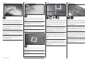
1
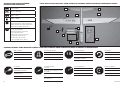
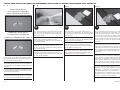
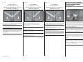
Ruddervators centered•
Leitwerk zentriert•
Gouvernes centrées•
Coda a V centrata
An important step in confi guring your model is to make
sure the ruddervators are operating correctly. Use the
following photos to check the mixing at your transmitter
to make sure the ruddervators move appropriately with
the control inputs.
Ein wichtiger Schritt in der Konfi guration des Modells
ist, dass die Ruder korrekt arbeiten. Nutzen Sie
die folgenden Fotos um den Sendermischer und die
Funktionen zu überprüfen.
Une des étapes les plus importantes est la confi guration
des commandes de l’empennage en “V”. Basez-vous sur
les photos suivantes pour contrôler les mouvements des
gouvernes en fonction des commandes.
Un punto importante nella confi gurazione del
modello, è quello di verifi care che i piani di coda a V
funzionino correttamente. Usare le immagini seguenti
per controllare che le miscelazioni impostate sul
trasmettitore siano corrette.
2
Up Elevator•
Höhenruder nach oben•
Manche de profondeur vers le bas•
Elevatore verso l’alto
Both the right and left ruddervators move up with an up
elevator input at the transmitter.
Beide Ruder bewegen sich nach oben mit der
Steuereingabe Höhenruder nach oben.
Les deux gouvernes doivent s’incliner vers le haut.
Entrambi i semi piani si devono muovere verso
l’alto quando si dà il comando corrispondente sul
trasmettitore.
RUDDERVATOR CONTROL THROW DIRECTIONS•RUDERAUSSCHLÄGE
UND RICHTUNGEN•DÉBATTEMENT ET DIRECTION DES GOUVERNES•
CONTROLLO CORSE ELEVATORE

23
EFL Allusive 2.2m
3
Down Elevator•
Höhenruder nach unten•
Manche de profondeur vers le haut•
Elevatore verso il basso
Both the right and left ruddervators move down with an
down elevator input at the transmitter.
Beide Ruder Ruder bewegen sich nach unten mit der
Steuereingabe Höhenruder nach unten.
Les deux gouvernes doivent s’incliner vers le bas.
Entrambi i semi piani si devono muovere verso
il basso quando si dà il comando corrispondente
sul trasmettitore.
4
Right Rudder•
Seitenruder rechts•
Manche de dérive vers la droite•
Timone verso destra
The right ruddervator moves down and the left
ruddervator moves up with a right rudder input
at the transmitter.
Bei der Funktion rechtes Seitenruder bewegt sich
das rechte V-Leitwerksruder nach unten, das linke
V-Leitwerksruder nach oben.
La gouverne de droite s’incline vers le bas et la gouverne
de gauche s’incline vers le haut.
Il semi piano di destra si muove verso il basso e quello
di sinistra verso l’alto quando, sul trasmettitore, si dà
comando timone verso destra.
5
Left Rudder•
Seitenruder links•
Manche de dérive vers la gauche•
Timone verso sinistra
The right ruddervator moves up and the left ruddervator
moves down with a left rudder input at the transmitter.
Bei der Funktion linkes Seitenruder bewegt sich
das rechte V-Leitwerksruder nach oben, das linke
V-Leitwerksruder nach unten.
La gouverne de droite s’incline vers le haut et la
gouverne de gauche s’incline vers le bas.
Il semi piano di destra si muove verso l’alto e quello di
sinistra verso il basso quando, sul trasmettitore, si dà
comando timone verso sinistra.
SETTING THE CONTROL THROWS•
EINSTELLEN DER RUDERAUSSCHLÄGE•
CONTRÔLE DU DÉBATTEMENT
DES GOUVERNES•
IMPOSTARE LE CORSE DEI COMANDI
1
Use scissors to trim the control throw tool from Page
34. Glue the tool to a piece of card stock and use the
tool to measure the control throws. Make sure the tool
is resting fl at on both the fi xed and movable surfaces
when setting the control throws.
Schneiden Sie die Einstellehre auf Seite 34 mit einer
Schere aus und kleben diese auf ein Stück Karton. Setzen
Sie die Lehre auf die feste und bewegliche Ruderfl äche
auf und stellen dann die Ausschläge danach ein.
Utilisez des ciseaux pour découper l’outil de mesure
du débattement situé à la page 34. Collez cet outil sur
de la carte plastique et utilisez l’outil pour contrôler le
débattement. L’outil doit être parfaitement à plat sur la
surface fi xe et la surface mobile quand vous effectuez le
contrôle.
Con le forbici ritagliare dalla pagina 34 l’attrezzo per il
controllo delle corse e incollarlo su di un cartoncino per
poterlo usare. Quando si fa la misura, accertarsi che
l’attrezzo sia ben appoggiato sia alla parte mobile che a
quella fi ssa delle superfi ci mobili.

24
EFL Allusive 2.2m
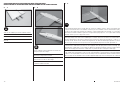
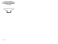
CENTER OF GRAVITY
An important part of preparing the aircraft for fl ight is
properly balancing the model.
1. Your model should be fl ight-ready with the battery
secured in the fuselage before balancing.
2. The recommended Center of Gravity (CG) location for
your model is 2
1
/
2
inches (65mm) back from the leading
edge of the wing against the fuselage as shown. Mark
the location of the CG on the bottom of the wing.
3. When balancing your model, make sure it is
assembled and ready for fl ight. Support the plane upright
at the marks made on the wing with your fi ngers or
a commercially available balancing stand. This is the
correct balance point for your model.
DER SCHWERPUNKT
Ein sehr wichtiger Teil in der Flugvorbereitung ist es das
Flugzeug richtig auszubalancieren.
1. Das Modell sollte vor dem Einstellen des
Schwerpunktes fl ugfertig mit montiertem Akku
ausgerüstet sein.
2. Der empfohlene Schwerpunkt (CG) des Modells
befi ndet sich 65mm von der vorderen Tragfl ächenkante
nach hinten gemessen wie abgebildet. Markieren Sie die
Position auf der Unterseite der Tragfl äche.
3. Das Modell muß bei dem Ausbalancieren fl ugfertig
ausgerüstet sein. Halten Sie das Modell aufrecht auf
ihren Fingerspitzen auf dem markierten Schwerpunkt
oder nutzen Sie dazu eine geeignete Schwerpunktwaage.
CENTRE DE GRAVITÉ
Une des étapes importantes de la préparation d’un
modèle est son équilibrage.
1. Votre modèle doit être en état de vol avec la batterie
installée pour effectuer le centrage du centre de gravité.
2. La position recommandée du Centre de Gravité (CG)
pour votre modèle se situe, comme illustré, entre 65mm
en arrière du bord d’attaque de l’aile. Marquez la position
du CG sur le dessous de l’aile.
3. Quand vous équilibrez votre modèle soyez sûr qu’il
est correctement assemblé et en ordre de vol. Soulevez
l’avion au niveau des marques à l’aide de vos doigts ou
d’un équilibreur vendu dans le commerce. C’est le point
d’équilibre correct pour votre modèle.
CENTRO DI GRAVITA’ (BARICENTRO)
Un punto importante per preparare l’aereo al volo è
quello di fare un centraggio corretto.
1. Il vostro modello dovrebbe essere pronto al volo con la
batteria fi ssata alla fusoliera prima del bilanciamento.
2. La posizione del baricentro consigliata si trova a
65mm dietro al bordo di entrata dell’ala nel punto in cui
si unisce alla fusoliera. Segnare la posizione del CG nella
parte superiore dell’ala.
3. Quando si fa il bilanciamento bisogna essere certi che
il modello sia completamente montato e pronto al volo.
Tenere sospeso l’aereo appoggiando le dita o un attrezzo
per il bilanciamento in corrispondenza del punto segnato
prima. Questo è il punto giusto per bilanciare questo
modello.
CAUTION: You must adjust your aircraft’s
center of gravity and balance your model properly
before attempting fl ights.
ACHTUNG: Der Schwerpunkt muß vor dem
Erstfl ug korrekt ausbalanciert sein.
ATTENTION: le centre de gravité de votre
modèle doit être parfaitement ajusté avant de
tenter un vol.
ATTENZIONE: prima di andare in volo è
necessario regolare accuratamente la posizione
del Baricentro (CG).
Page is loading ...
Page is loading ...
Page is loading ...
Page is loading ...
Page is loading ...
Page is loading ...
Page is loading ...
Page is loading ...
Page is loading ...
Page is loading ...
Page is loading ...
Page is loading ...
-
 1
1
-
 2
2
-
 3
3
-
 4
4
-
 5
5
-
 6
6
-
 7
7
-
 8
8
-
 9
9
-
 10
10
-
 11
11
-
 12
12
-
 13
13
-
 14
14
-
 15
15
-
 16
16
-
 17
17
-
 18
18
-
 19
19
-
 20
20
-
 21
21
-
 22
22
-
 23
23
-
 24
24
-
 25
25
-
 26
26
-
 27
27
-
 28
28
-
 29
29
-
 30
30
-
 31
31
-
 32
32
-
 33
33
-
 34
34
-
 35
35
-
 36
36


E-flite Allusive 2.2m User manual
- Category
- Remote controlled toys
- Type
- User manual
Ask a question and I''ll find the answer in the document
Finding information in a document is now easier with AI
in other languages
- italiano: E-flite Allusive 2.2m Manuale utente
- français: E-flite Allusive 2.2m Manuel utilisateur
- Deutsch: E-flite Allusive 2.2m Benutzerhandbuch
Related papers
-
E-flite Mystique EFL4905 User manual
-
arf PA-20 Pacer 10e Owner's manual
-
E-flite MLP6DSM User manual
-
-
-
E-flite J-3 Cub 450 User manual
-
-
-
-
E-flite Carbon-Z Cub User manual
Other documents
-
Horizon Hobby Mystique RES 2.9m ARF User manual
-
 Hangar 9 HAN6030 Owner's manual
-
Spektrum SPMA3060 Owner's manual
-
HobbyZone Faze RTF User manual
-
-
Black Horse Model Heinkel He 111 User manual
-
Evolution EVOE10GX User manual
-
Blade Pico QX RTF User manual
-
-
 Hangar 9 HAN5065 Owner's manual

