NEC LCD205WXM User manual

Category
TVs & monitors
Type
User manual
TCO’03
Congratulations!
The display you have just purchased carries the TCO’03 Displays
label. This means that your display is designed, manufactured and
tested according to some of the strictest quality and environmental
requirements in the world. This makes for a high performance
product, designed with the user in focus that also minimizes the
impact on our natural environment.
Some of the features of the TCO’03 Display requirements:
Ergonomics
Good visual ergonomics and image quality in order to improve the working environment for
the user and to reduce sight and strain problems. Important parameters are luminance,
contrast, resolution, reflectance, color rendition and image stability.
Energy
Energy-saving mode after a certain time – beneficial both for the user and the environment
Electrical safety
Emissions
Electromagnetic fields
Noise emissions
Ecology
The product must be prepared for recycling and the manufacturer must have a certified
environmental management system such as EMAS or ISO 14 001
Restrictions on:
- chlorinated and brominated flame retardants and polymers
- heavy metals such as cadmium, mercury and lead.
The requirements included in this label have been developed by TCO Development in co-operation
with scientists, experts, users as well as manufacturers all over the world. Since the end of the
1980s TCO has been involved in influencing the development of IT equipment in a more user-
friendly direction. Our labelling system started with displays in 1992 and is now requested by users
and IT-manufacturers all over the world.
For more information, please visit
www.tcodevelopment.com
00_Cover 6/6/07, 8:36 AM2
Manufacturers Recycling and Energy Information
NEC DISPLAY SOLUTIONS is strongly committed to environmental protection and sees recycling
as one of the company’s top priorities in trying to minimize the burden placed on the environment.
We are engaged in developing environmentally-friendly products, and always strive to help define
and comply with the latest independent standards from agencies such as ISO (International
Organisation for Standardization) and TCO (Swedish Trades Union).
Disposing of your old NEC product
The aim of recycling is to gain an environmental benefit by means of re-use, upgrading,
reconditioning or reclamation of material. Dedicated recycling sites ensure that environmentally
harmful components are properly handled and securely disposed. To ensure the best recycling of
our products, NEC DISPLAY SOLUTIONS offers a variety of recycling procedures and gives
advice on how to handle the product in an environmentally sensitive way, once it has reached the
end of its life.
All required information concerning the disposal of the product and country-specific information on
recycling facilities can be found on our following websites:
http://www.nec-display-solutions.com/greencompany/ (in Europe),
http://www.nec-display.com (in Japan) or
http://www.necdisplay.com (in USA).
Energy Saving
This monitor features an advanced energy saving capability. When a VESA Display Power
Management Signalling (DPMS) Standard signal is sent to the monitor, the Energy Saving mode is
activated. The monitor enters a single Energy Saving mode.
WEEE Mark (European Directive 2002/96/EC)
Within the European Union
EU-wide legislation, as implemented in each Member State, requires that waste
electrical and electronic products carrying the mark (left) must be disposed of
separately from normal household waste. This includes monitors and electrical
accessories, such as signal cables or power cords. When you need to dispose of
your NEC display products, please follow the guidance of your local authority, or
ask the shop where you purchased the product, or if applicable, follow any
agreements made between yourself and NEC.
The mark on electrical and electronic products only applies to the current European Union Member
States.
Outside the European Union
If you wish to dispose of used electrical and electronic products outside the European Union, please
contact your local authority so as to comply with the correct disposal method.
Mode Power consumption LED color
Normal Operation Approx. 45W (LCD205WXM) Green
Approx. 48W (LCD225WXM)
Energy Saving Mode Less than 2W Orange
Off Mode Less than 1W Unlit
00_Cover 6/6/07, 8:36 AM3
Chinese RoHS-information relevant for Chinese market
00_Cover 6/6/07, 8:36 AM4
English-1
English
Declaration of the Manufacturer
We hereby certify that the color monitor MultiSync LCD205WXM
(L206T8)/MultiSync LCD225WXM (L226T9) are in compliance with
Council Directive 73/23/EEC:
– EN 60950-1
Council Directive 89/336/EEC:
– EN 55022
– EN 61000-3-2
– EN 61000-3-3
– EN 55024
RISK OF ELECTRIC SHOCK • DO NOT OPEN
TO PREVENT FIRE OR SHOCK HAZARDS, DO NOT EXPOSE THIS UNIT TO RAIN OR MOISTURE. ALSO, DO NOT USE THIS UNIT’S
POLARIZED PLUG WITH AN EXTENSION CORD RECEPTACLE OR OTHER OUTLETS UNLESS THE PRONGS CAN BE FULLY INSERTED.
REFRAIN FROM OPENING THE CABINET AS THERE ARE HIGH VOLTAGE COMPONENTS INSIDE. REFER SERVICING TO QUALIFIED
SERVICE PERSONNEL.
WARNING
CAUTION: TO REDUCE THE RISK OF ELECTRIC SHOCK,
DO NOT REMOVE COVER (OR BACK). NO USER
SERVICEABLE PARTS INSIDE. REFER SERVICING
TO QUALIFIED SERVICE PERSONNEL.
This symbol warns user that uninsulated voltage
within the unit may have sufficient magnitude to cause
electric shock. Therefore, it is dangerous to make any
kind of contact with any part inside this unit.
This symbol alerts the user that important literature
concerning the operation and maintenance of this
unit has been included. Therefore, it should be read
carefully in order to avoid any problems.
CAUTION
and marked with
NEC Display Solutions, Ltd.
4-13-23, Shibaura,
Minato-Ku
Tokyo 108-0023, Japan
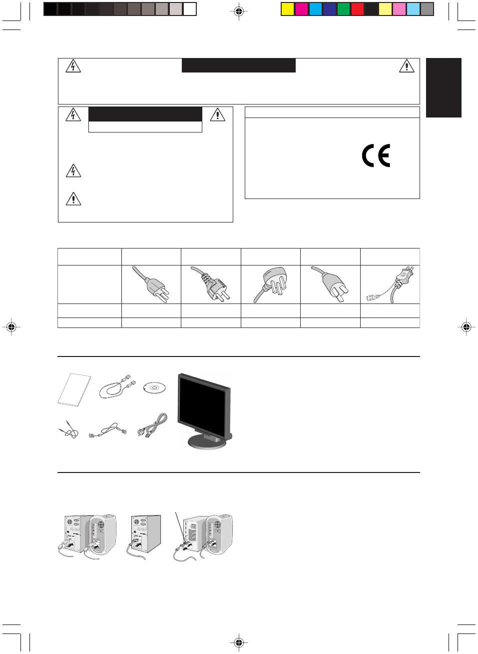
Contents
Your new NEC MultiSync LCD monitor box* should contain the
following:
MultiSync LCD monitor with tilt base
Audio Cable
Power Cord
•Video Signal Cable (15-pin mini D-SUB male to 15-pin mini
D-SUB male)
•Video Signal Cable (DVI-D to DVI-D) (for Europe)
User’s Manual
CD-ROM
*
Remember to save your original box and packing material to transport or ship
the monitor.
User’s
Manual
Audio
Cable
Power Cord*
15-pin mini D-SUB
male to 15-pin mini
D-SUB male
DVI-D to DVI-D
(for Europe)
MultiSync LCD monitor
Quick Start
To attach the MultiSync LCD monitor to your system, follow these
instructions:
1. Turn off the power to your computer.
2. For the PC or MAC with DVI digital output: Connect the DVI-D
signal cable (not included for the U.S. and China) to the connector of
the display card in your system (Figure A.1). Tighten all screws.
For the PC with Analog output: Connect the 15-pin mini D-SUB
signal cable to the connector of the display card in your system
(Figure A.2). Tighten all screws.
For the MAC: Connect the MultiSync Macintosh cable adapter
(not included) to the computer. Attach the 15-pin mini D-SUB signal
cable to the MultiSync Macintosh cable adapter (Figure A.3).
Tighten all screws.
NOTE: Some Macintosh systems do not require a Macintosh cable
adapter.
Figure A.1 Figure A.2
Macintosh Cable Adapter (not included)
CD-ROM
Figure A.3
User’s
Manual
* Type of power cord included will depend on the where the LCD monitor is to be shipped.
CAUTION: Please use the power cord provided with this display in accordance with the table below. If a power cord is not supplied with this
equipment, please contact your supplier. For all other cases, please use a power cord that matches the AC voltage of the power outlet and has
been approved by and complies with the safety standard of your particular country.
Plug Type North America
European Continental
U.K. Chinese Japanese
Plug Shape
Country
Voltage
U.S.A./Canada U.K. China JapanEU (except U.K.)
120*
230 220 100230
* When operating the MultiSync LCD205WXM/LCD225WXM monitor with its AC 125-240V power supply, use a power supply cord that matches
the power supply voltage of the AC power outlet being used.
NOTE: This product can only be serviced in the country where it was purchased.
01_English 6/6/07, 8:36 AM1
English-2
English
Figure C.1
Power Button
Figure TS.1
Figure R.1
Non-abrasive surface
Figure R.2
Figure R.3
4-SCREWS (M4)
MAX depth: 8.5mm
If use other screw,
check length of screw.
Weight of LCD assembly: 6.0 kg (MAX) (LCD205WXM)
6.3 kg (MAX) (LCD225WXM)
Specifications
Replace screws
Tighten all
screws
100 mm
Thickness
of Bracket (Arm)
2.0 ~ 3.2 mm
3. Remove the Cable management cover (Figure A.4).
4. Connect all cables to the appropriate connector on the back of the
monitor (Figure B.1). Connect Headphones
(not included) to the appropriate connector at the rear side of the
monitor, if desired (Figure B.1).
5. Connect one end of the power cord to the monitor and the other
end to the power outlet. Position the Video Signal Cable, Audio
cable and power cord between the holes on the Stand.
6. To attach the Cable management cover, insert the tabs of the
Cable management cover into the holes on the Stand and slide
the Cable management cover downward into place (Figure B.1)
making sure that the tabs are completely secure.
NOTE: Adjust the position of the cables that are placed under the
Cable management cover to avoid damaging the cable or
monitor.
NOTE: Please refer to the Caution section of this manual for proper
selection of power cord.
7. Turn on the monitor with the front power button and the computer
(Figure C.1).
8. No-touch Auto Adjust automatically adjusts the monitor to optimal
settings upon initial setup for most timings (Analog input only).
For further adjustments, use the following OSD controls:
Auto Contrast
Auto Adjust
Refer to the Controls section of this User’s Manual for a full
description of these OSD controls.
NOTE: If you have any problem, please refer to the
Troubleshooting section (CD-ROM).
Raise and Lower Monitor Screen
The monitor may be raised or lowered. To raise or lower screen, place
hands on each side of the monitor and lift or lower to the desired
height (Figure RL.1).
NOTE: Handle with care when raising or lowering the monitor
screen.
Tilt and Swivel
Grasp both sides of the monitor screen with your hands and adjust
the tilt and swivel as desired (Figure TS.1).
NOTE:
Handle with care when tilting and swivelling the monitor screen.
Remove Monitor Stand for Mounting
To prepare the monitor for alternative mounting purposes:
1. Disconnect all cables.
2. Place monitor face down on a non-abrasive surface (Figure R.1).
3. Remove the 4 screws connecting the monitor to the stand and
remove the stand as indicated (Figure R.2). The monitor is now
ready for mounting in an alternative manner.
4. Connect all cables to the back of the monitor (Figure R.3).
5. Reverse this process to re-attach stand.
NOTE: Use only VESA-compatible alternative mounting method.
NOTE: Handle with care when removing monitor stand.
Connecting a Flexible Arm
This LCD monitor is designed for use with a flexible arm.
Please use the attached screws (4pcs) as shown in the picture when
installing. To meet the safety requirements, the monitor must be
mounted to an arm which guaranties the necessary stability under
consideration of the weight of the monitor. The LCD monitor shall only
be used with an approved arm (e.g. GS mark).
100 mm
Figure RL.1
Base
Stand
Cable management cover
Figure A.4
Power Cable
Cable
management
cover
Connect to Computer
audio output
Figure B.1
Input (VGA)
Input (Audio)
Input (DVI)
Headphone
01_English 6/6/07, 8:36 AM2
English-3
English
Controls
OSD (On-Screen-Display) control buttons on the front of the monitor function as follows:
1. Basic function at pressing each key
Showing OSD. Shortcut to Brightness
adjust Menu.
Button
At No OSD
showing
Shortcut to Volume adjust
Menu.
At OSD showing
(Icon selection stage)
Go to Adjustment stage. Cursor goes to left. Cursor goes to right.
At OSD showing
(Adjustment stage)
Go to Icon selection stage. Adjust value decrease or
Cursor for adjust goes to
left.
Adjust value increase or
Cursor for adjust goes to
right.
SELECT
+
Input signal select.
Reset operation.
Mute off/on switch on
Volume adjustment Menu.
1<->2 / RESET
Sub Menu
(Icon Select)
Press
“–” or “+”
Sub Menu (Adjust)
Press “SELECT” key
Press
“–” or “+”
Example Tool:
Press “SELECT” key
Press “SELECT” key
Main Menu
(Icon Select, Analog Input)
Main Menu (Adjust)
Press
“SELECT”
key
Press
“SELECT”
key
Press “SELECT” key
Adjust by using
“–” or “+”
Adjust by using
“–” or “+”
VOLUME
Control the sound volume of speakers and headphone.
To mute the speaker sound, press the 1<->2/RESET key.
BRIGHTNESS
Adjusts the overall image and background screen brightness.
CONTRAST
Adjusts the image brightness in relation to the background.
AUTO CONTRAST (Analog Input only)
Adjusts the image displayed for non-standard video inputs.
AUTO ADJUST (Analog Input only)
Automatically adjusts the Image Position, the H. Size and
Fine setting.
LEFT/RIGHT (Analog Input only)
Controls Horizontal Image Position within the display area of
the LCD.
DOWN/UP (Analog Input only)
Controls Vertical Image Position within the display area of the
LCD.
H. SIZE (Analog Input only)
Adjusts the horizontal size by increasing or decreasing this
setting.
FINE (Analog Input only)
Improves focus, clarity and image stability by increasing or
decreasing this setting.
COLOR CONTROL SYSTEMS
Five color presets (9300/7500/sRGB/USER/NATIVE) select
the desired color setting.
The sRGB and NATIVE, color presets are standard and
cannot be changed.
COLOR RED
Increase or decreases Red. The change will appear on
screen.
COLOR GREEN
Increase or decreases Green. The change will appear on
screen.
COLOR BLUE
Increase or decreases Blue. The change will appear on
screen.
TOOL
Selecting TOOL allows you to get into the sub menu.
FACTORY PRESET
Selecting Factory Preset allows you to reset all OSD control
settings back to the factory settings. The RESET button will
need to be held down for several seconds to tage effect.
Individual settings can be reset by highlighting the control to
be reset and pressing the RESET button.
EXIT
Selecting EXIT allows you exit OSD menu/ sub menu.
LANGUAGE
OSD control menus are available in nine languages.
OSD TURN OFF
The OSD control menu will stay on as long as it is in use. In
the OSD Turn OFF submenu, you can select how long the
monitor waits after the last touch of a button to shut off the
OSD control menu. The preset choices are 10 - 120 seconds
by 5 seconds step.
2. OSD structure
01_English 6/6/07, 8:37 AM3
English-4
English
OSD LOCK OUT
This control completely locks out access to all OSD control
functions without Volume, Brightness and Contrast. When
attempting to activate OSD controls while in the Lock Out
mode, a screen will appear indicating the OSD are locked
out. To activate the OSD Lock Out function, press “1<->2/
RESET”, then “+” key and hold down simultaneously. To de-
activate the OSD Lock Out, press “1<->2/ RESET”, then “+”
key and hold down simultaneously.
RESOLUTION NOTIFIER
If ON is selected, a message will appear on the screen after
45 seconds, notifying you that the resolution is not at optimal
resolution.
MONITOR INFO
Indicates the model and serial numbers of your monitor.
EXPANSION
Selects the zoom mode.
FULL: The image is expanded to 1680 x 1050, regardless of
resolution.
ASPECT: The image is expended without changing the
aspect ratio.
DDC/CI
Turns ON or OFF the two way communication and control of
the monitor.
INPUT RESOLUTION (Analog Input Only)
Sets of the resolution of input signal to one of the following:
When vertical active size is 768, you can select resolution
from 1024 x 768, 1280 x 768, 1360 x 768.
When vertical active size is 1050, you can select resolution
from 1400 x 1050, 1680 x 1050.
OSD Warning
OSD Warning menus disappear with SELECT button.
NO SIGNAL: This function gives a warning when there is no
signal present. After power is turned on or when there is a
change of input signal or video is inactive, the No Signal
window will appear.
RESOLUTION NOTIFIER: This function gives a warning of
use with optimized resolution. After power is turned on or
when there is a change of input signal or the video signal
doesn’t have proper resolution, the Resolution Notifier
window will open. This function can be disabled in the TOOL
menu.
OUT OF RANGE: This function gives a recommendation of
the optimized resolution and refresh rate. After the power is
turned on or there is a change of input signal or the video
signal doesn’t have proper timing, the Out Of Range menu
will appear.
01_English 6/6/07, 8:37 AM4
Printed in China
Part Number: 1E505392
Printed on recycled paper
xx_Back 6/6/07, 8:38 AM2
  • Page 1 1
  • Page 2 2
  • Page 3 3
  • Page 4 4
  • Page 5 5
  • Page 6 6
  • Page 7 7
  • Page 8 8
  • Page 9 9
  • Page 10 10
  • Page 11 11
  • Page 12 12
  • Page 13 13
  • Page 14 14
  • Page 15 15
  • Page 16 16
  • Page 17 17
  • Page 18 18
  • Page 19 19
  • Page 20 20
  • Page 21 21
  • Page 22 22
  • Page 23 23
  • Page 24 24
  • Page 25 25
  • Page 26 26
  • Page 27 27
  • Page 28 28
  • Page 29 29
  • Page 30 30

NEC LCD205WXM User manual

Category
TVs & monitors
Type
User manual

Ask a question and I''ll find the answer in the document

Finding information in a document is now easier with AI