Page is loading ...

UNITY/I
UT3K, UT4K, UT5K, UT8K
Single-Phase Uninterruptible Power Systems
Systèmes d’alimentation monophasée sans interruption
Sistemas monofásicos de suministro ininterrumpido de energía
User Manual
Manuel d’utilisation
Manual del usuario
MLS-0350C
Copyright 1994-1997, Best Power. All rights reserved.
®

1
Table of Contents
Introduction . . . . . . . . . . . . . . . . . . . . . . . . . . . . . . . . . . . . . . . . . . . . . . . . . . . . . . . . . . . . . . . . . . . . . . . . . . . . . . . . . .3
001 Storing the UNITY/I UPS . . . . . . . . . . . . . . . . . . . . . . . . . . . . . . . . . . . . . . . . . . . . . . . . . . . . . . . . . . . . . . . . .3
002 If You Have a Question . . . . . . . . . . . . . . . . . . . . . . . . . . . . . . . . . . . . . . . . . . . . . . . . . . . . . . . . . . . . . . . . . . .3
100 Starting the UNITY/I UPS . . . . . . . . . . . . . . . . . . . . . . . . . . . . . . . . . . . . . . . . . . . . . . . . . . . . . . . . . . . . . . . . . . . .3
101 Startup . . . . . . . . . . . . . . . . . . . . . . . . . . . . . . . . . . . . . . . . . . . . . . . . . . . . . . . . . . . . . . . . . . . . . . . . . . . . . . . .4
102 Setting the Time and Date . . . . . . . . . . . . . . . . . . . . . . . . . . . . . . . . . . . . . . . . . . . . . . . . . . . . . . . . . . . . . . . . .6
200 Operation . . . . . . . . . . . . . . . . . . . . . . . . . . . . . . . . . . . . . . . . . . . . . . . . . . . . . . . . . . . . . . . . . . . . . . . . . . . . . . . . .7
201 Front Panel Lights . . . . . . . . . . . . . . . . . . . . . . . . . . . . . . . . . . . . . . . . . . . . . . . . . . . . . . . . . . . . . . . . . . . . . . .7
202 Front Panel Keys and Display . . . . . . . . . . . . . . . . . . . . . . . . . . . . . . . . . . . . . . . . . . . . . . . . . . . . . . . . . . . . . .7
203 Inside the Front Door . . . . . . . . . . . . . . . . . . . . . . . . . . . . . . . . . . . . . . . . . . . . . . . . . . . . . . . . . . . . . . . . . . . . .8
204 Alarms: What They Mean and What to Do About Them . . . . . . . . . . . . . . . . . . . . . . . . . . . . . . . . . . . . . . .9
205 If You Have an Extended Power Outage . . . . . . . . . . . . . . . . . . . . . . . . . . . . . . . . . . . . . . . . . . . . . . . . . . . . .12
206 Shutting Down the UNITY/I UPS . . . . . . . . . . . . . . . . . . . . . . . . . . . . . . . . . . . . . . . . . . . . . . . . . . . . . . . . . .12
300 Parameters . . . . . . . . . . . . . . . . . . . . . . . . . . . . . . . . . . . . . . . . . . . . . . . . . . . . . . . . . . . . . . . . . . . . . . . . . . . . . . .13
301 Displaying Parameters . . . . . . . . . . . . . . . . . . . . . . . . . . . . . . . . . . . . . . . . . . . . . . . . . . . . . . . . . . . . . . . . . . .13
302 Changing Parameter Values . . . . . . . . . . . . . . . . . . . . . . . . . . . . . . . . . . . . . . . . . . . . . . . . . . . . . . . . . . . . . . .13
303 Parameter Table . . . . . . . . . . . . . . . . . . . . . . . . . . . . . . . . . . . . . . . . . . . . . . . . . . . . . . . . . . . . . . . . . . . . . . . .14
400 Maintenance and Service . . . . . . . . . . . . . . . . . . . . . . . . . . . . . . . . . . . . . . . . . . . . . . . . . . . . . . . . . . . . . . . . . . . .18
401 Regular Maintenance . . . . . . . . . . . . . . . . . . . . . . . . . . . . . . . . . . . . . . . . . . . . . . . . . . . . . . . . . . . . . . . . . . . .18
402 Worldwide Service . . . . . . . . . . . . . . . . . . . . . . . . . . . . . . . . . . . . . . . . . . . . . . . . . . . . . . . . . . . . . . . . . . . . . .18
403 Accessing the Alarm and System Logs . . . . . . . . . . . . . . . . . . . . . . . . . . . . . . . . . . . . . . . . . . . . . . . . . . . . . .18
500 Specifications . . . . . . . . . . . . . . . . . . . . . . . . . . . . . . . . . . . . . . . . . . . . . . . . . . . . . . . . . . . . . . . . . . . . . . . . . . . . .20
600 Options.. . . . . . . . . . . . . . . . . . . . . . . . . . . . . . . . . . . . . . . . . . . . . . . . . . . . . . . . . . . . . . . . . . . . . . . . . . . . . . . . . .23
Appendix A: Remote Emergency Power Of (EPO) . . . . . . . . . . . . . . . . . . . . . . . . . . . . . . . . . . . . . . . . . . . . . . . . . . . .24
Appendix B: Attaching the Stabilizer Bracket . . . . . . . . . . . . . . . . . . . . . . . . . . . . . . . . . . . . . . . . . . . . . . . . . . . . . . . .25
Warranty. . . . . . . . . . . . . . . . . . . . . . . . . . . . . . . . . . . . . . . . . . . . . . . . . . . . . . . . . . . . . . . . . . . . . . . . . . . . . . . . . . . . .25
This manual is for units with ROM version 2.02.
º
CAUTION!
All uninterruptible power systems (UPS) units contain dangerous voltages.
The unit can provide power from its batteries. To avoid possible personal injury or equipment damage,
assume that hazardous voltage is present at the unit’s output any time AC input power or DC battery voltage
is applied. To make certain there is no output voltage, turn the unit off, unplug the unit, and disconnect all
DC sources.
For units with line cords, the power supply cord is intended to serve as the disconnect device. The socket-out-
let shall be near the equipment and shall be easily accessible.
Before maintenance or repair, all connections must be removed. Before maintenance, repair, or shipment, the
unit must be completely switched off and unplugged or disconnected.
E
N
G
L
I
S
H

2
IMPORTANT SAFETY INSTRUCTIONS
SAVE THESE INSTRUCTIONS
This manual contains important instructions for your UNITY/I UPS.
The installation and use of this product must comply with all national, federal, state, municipal or local codes that apply. If
you need help, please have your UPS model and serial number and call Best Power’s Worldwide Service at 1-800-356-5737
(U.S.A. or Canada) or 1-608-565-2100. Outside of the U.S.A. and Canada, you can also call the nearest Best Power office
for more information.
Best Power
P.O. Box 280
Necedah, Wisconsin 54646 U.S.A.
Telephone: 1-608-565-7200
Toll-free (U.S.A. and Canada): 1-800-356-5794
FAX: 1-608-565-2221
International Fax: 1-608-565-7675
E-mail: [email protected]
Best Power Technology Mexico, S.A. de C.V.
Golfo de Riga, 34
Colonia Tacuba
Mexico D.F. 11410
MEXICO
Telephone: (52) 5-527-8009
Toll-free (in Mexico): 1-800-711-8978
FAX: (52) 5-399-1320
E-mail: [email protected]
Best Power Technology, Pte. Ltd.
19 Neyhal Road
SINGAPORE 628584
Telephone: (65) 265-6866
FAX: (65) 265-6636
E-mail: [email protected]
Sola Australia Ltd.
13 Healey Road
Dandenong Victoria 3175
AUSTRALIA
Telephone: (61) 3-9706-5022
FAX: (61) 3-9794-9150
E-mail: [email protected]
Best Power Technology Limited
BEST House
Wykeham Industrial Estate
Moorside Road
Winchester, Hampshire
SO23 7RX
ENGLAND
Telephone: (44) 1962-844414
Toll-free (in England): 0800-378444
FAX: (44) 1962-841846
E-mail: [email protected]
Best Power Technology Germany, GmbH
Am Weichselgarten 23
D-91058 Erlangen
GERMANY
Telephone: (49) 9131-77700
Toll-free (in Germany)i: 0130-84-7712
FAX: (49) 9131-7770-444
E-mail: [email protected]
Borri Elettronica Industriale Srl
Via dei Lavoratori, 124
20092 Cinisello Balsamo (Mi)
Milan, ITALY
Telephone: (39) 2-6600661-2
FAX: (39) 02-6122481
IF THE UPS IS SOUNDING AN ALARM and you need to know what the alarm means and how to respond, turn to
Section 204. To silence the audible alarm, press the [CANCEL] key. Silencing the audible alarm does not correct the con-
dition that caused the alarm.
E
N
G
L
I
S
H

3
Introduction
The UNITY/I™ UPS is easy to start and operate. Once you start the UPS, it provides continuous, computer-grade
power to your equipment. The UPS keeps you informed of its status with its front panel lights, four-digit display, and
audible signals (beeper). Using the display and front panel keys, you can display UPS information and program some
features.
This manual tells you how to start and operate the UNITY/I UPS. Begin with Section 100, “Starting the UNITY/I
UPS,” which will help you determine whether you need to do any installation before you start the UPS.
001 Storing the UNITY/I UPS
If you are not going to use the UPS right away, store it between -20° and +40° Celsius (-4° to +104° F). If you remove
the batteries and store them separately, you can store the UPS at -20° to +60° Celsius (-4° to +140° F). Batteries have a
longer shelf life if you store them below 25° Celsius (77° F). Recharge stored batteries every 90 to 120 days.
002 If You Have a Question
Best Power is committed to outstanding customer service. Worldwide Service is happy to help you with your problems
or questions. A service technician is available 24 hours a day, 365 days a year. Just call Worldwide Service or the
nearest Best Power office, or send a fax to the Worldwide Service fax number. Please have your unit’s serial number
available when you call; this number is inside the front door of the UPS.
If you prefer to contact Best Power via computer, you can use Best Power’s World Wide Web site to get more product
information.
Best Power’s toll-free Fax-on-Demand service is also available 24 hours a day to give you access to technical notes and
product information.
Worldwide Service: 1-800-356-5737 (U.S., Canada) or 1-608-565-2100
Worldwide Service FAX: 1-608-565-7642 or 1-608-565-2509
World Wide Web Site: http://www.bestpower.com
Sales Fax on Demand: 1-800-487-6813 (U.S. and Canada)
Service Fax on Demand: 1-608-565-9499 ext. 9000
100 Starting the UNITY/I UPS
If your UNITY/I UPS does not have an input line cord and plug, it is a hardwired unit and must be installed by a
qualified electrician (see the UNITY/I Installation Manual). After a qualified electrician has installed the UPS, or if the
UPS has an input plug, follow the instructions in this section to start the unit.
Make sure that the UPS is near the equipment it will protect. Leave at least 4 inches (100 mm) space on top of and
behind the UPS for ventilation. Do not put the UPS near a source of heat.
Make sure that the temperature is 0° to 40° Celsius (32° to 104° Fahrenheit) and the relative humidity is 0 to 95%
without condensation. The air must be free of dust, chemicals that corrode or other contaminants. Air must be free to
move around the unit. The batteries’ service life is longer if the operating ambient temperature stays below 25° C
(77° F).
E
N
G
L
I
S
H

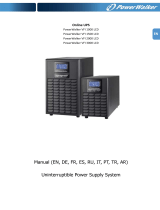
Front View* Back View*
101 Startup
1
If you have a UT3K, UT4K or UT5K: Attach the stabilizer bracket to the back of the
UPS (see Appendix B).
2
Open the UPS’ front door by pulling the top of the door toward you (see Figure 1 to find
the door). Make sure that the keyswitch inside the front door is turned to “Off” (see
Figure 2).
3
If your UNITY/I has an input line cord and plug: Plug in the UPS. If the plug does not
match the wall outlet, have a qualified electrician install the proper wiring and outlet.
If your UNITY/I is hardwired (does not have an input line
cord and plug), an electrician should have installed the UPS. An
external bypass/AC disconnect switch should be mounted on the
wall nearby (see Figure 3). Turn the UPS AC LINE
DISCONNECT SWITCH to “ON” and the UPS BYPASS
SWITCH to “OFF.”
4
Output
Receptacles
(optional)
Front Panel
Lights,
Display,
and Keys
Front Door
(Keyswitch
and Serial
Number
Inside)
Serial Number
Main Output
Circuit Breaker
(some models)
Communication
Port
Line Cord
DC Port
Grounding
Terminal
Stabilizer
Bracket
Figure 2
Figure 3
Figure 1
E
N
G
L
I
S
H
* The drawings in Figure 1 show a UT3K, UT4K or UT5K. The UT8K is similar in appearance.

5
4
If you have an external battery pack(s) (see Figure 4), refer to the
installation instructions that came with your battery pack(s). Then continue
with the steps below:
a. After completing the battery pack installation, hold down the Precharge
switch on the front of the battery cabinet for five seconds (see Figure 5).
b. Insert the key into the main DC switch on the front of the battery
cabinet. Turn it clockwise, then pull the switch out toward you. The
ON-LINE light will light on the battery pack cabinet.
5
Turn the keyswitch inside the front door of the UPS to “Auto” (see Figure 6). The yellow
BATTERY light will turn on briefly, then the green LINE light will turn on.
The four-digit display will show the estimated runtime in minutes and seconds (see Figure
7). For now, the estimated runtime is high because there is no equipment drawing power
from the UPS. If the red ALARM light is on,see Section 204 before you go on.
Note: Do not continue until the green LINE light is on. The
UPS is set at the factory to automatically select its
output frequency; to do this, the UPS must run on AC
line. If the UPS does not run on AC line the first time
you start it, you must either set parameters 14 and 15 or
wait until the green LINE light comes on before you
switch on the connected equipment. To set the
parameters, see Section 302.
6
Once you switch on the unit and the LINE light comes on, the
UPS will begin to charge the batteries. If this is the first time
you have started the UPS, let the UPS run on line for at least 24 hours to charge the batteries. You may use the UPS
right away; however, its battery runtime will be reduced until it fully charges the batteries.
7
If your UNITY/I has receptacles on the back, switch off the equipment you want to connect to the UPS. Then, plug
the equipment into the receptacles on the back of the UPS and switch on the equipment. If the red ALARM light comes
on, see Section 204.
If your UNITY/I does not have receptacles on the back,the electrician who installed the UNITY/I should have
connected your equipment to it. Turn the UPS BYPASS SWITCH (see Figure 3) to “UPS.” Then, switch on the
equipment connected to the UPS. If the red ALARM light comes on, see Section 204.
The UNITY/I UPS is now providing continuous, computer-grade power to your equipment and is ready to provide
battery backup power when needed.
Note: You may occasionally hear short “clicking” sounds inside the unit; these clicks are a normal part of unit
operation.
Figure 4
Figure 5
Precharge SwitchKeyswitch
UNITY/I Battery Pack
Figure 6
Figure 7
E
N
G
L
I
S
H

6
8
If you plan to use the CheckUPS software that came with your UPS, connect the interface cable from the UPS to
the computer system, with the “UPS” end connected to the UNITY/I.
Using CheckUPS with Windows 95: Shut down your computer and insert the CheckUPS CD. Restart the
computer. Follow the instructions in the CheckUPS package.
Using CheckUPS without Windows 95: Start the computer and follow the instructions in the CheckUPS package.
9
Fill out the warranty registration card in this manual and return it to Best Power. Please return the registration card
within ten days of installation.
102 Setting the Time and Date
The UPS stores the time, date, and year in parameters that you can program (see Section 300 for more about
parameters). These parameters must be programmed correctly so that the UPS can store accurate information in its
alarm and system logs. Whenever the UPS has been shut down, you should reset the time and date after you restart the
UPS. To set the time, date, and year parameters, follow the steps below.
Note: When the unit is in parameter mode, the functions of the front panel keys change. The label inside the front door
of the unit explains what the keys do when the UPS is in parameter mode. The label also shows a
“Programming Template” with different key names for parameter mode.
1. To enter the parameter mode, hold down the [CANCEL] and [RUNTIME] keys together. Release the keys when the
display changes to P-00 (for parameter 0).
2. Enter the user password (377) by following these steps:
a. Press [CANCEL]. The display should show 0 (the value of parameter 0).
b. Use the [%LOAD] key to change the display to 377. If you accidentally scroll past 377, use the [VOUT] key
to go back.
Note: If you hold downthe [%LOAD] or the [VOUT] key, the display will scroll more quickly after a few
seconds.
c. Press [RUNTIME]. The display should show I to show you have entered the user password.
d. Press [CANCEL]. The display should show P-00.
3. Set the year (parameter 91) by following these steps:
a. Use the [%LOAD] key to change the display to P-9I.
b. Press [CANCEL]. The display should show a year.
c. Use the [%LOAD] or the [VOUT] key to change the display to the correct year.
d. Press [RUNTIME]. The display should show the correct year.
e. Press [CANCEL]. The display should show P-91.
4. Set the date (parameter 90) by following these steps:
a. Use the [VOUT] key to change the display to P-90.
b. Press [CANCEL]. The display should show a date formatted as mm.dd (month.day).
c. Use the [%LOAD] or [VOUT] key to change the display reading to the correct month and day. For example, if
the date were March 27, you should enter “0327.”
d. Press [RUNTIME]. The display should show the correct date (mm.dd).
e. Press [CANCEL]. The display should show P-90.
5. Set the time (parameter 89) by following these steps:
a. Use the [VOUT] key to change the display to P-89.
b. Press [CANCEL]. The display should show a time formatted as hh:mm (hour:minute).
c. Use the [%LOAD] or [VOUT] key to change the display reading to the correct time in 24-hour time. For times
from 1 p.m. to 11:59 p.m., add twelve to the hour. For example, 2:30 p.m. would be 14:30.
d. Press [RUNTIME]. The display should show the correct time (in 24-hour time).
e. Press [CANCEL]. The display should show P-89.
6. To escape the parameter mode, press [VLINE] twice.
E
N
G
L
I
S
H

7
200 Operation
Once you start the UNITY/I UPS, it operates automatically. The UNITY/I keeps you informed of its status with its front
panel lights and four-digit display. If you wish, you can also use the front panel keys and four-digit display to view
information about the UPS. In addition, the UPS has alarms that will alert you to UPS conditions that require your
attention.
201 Front Panel Lights
The lights on the front panel tell you several things about the operating status of the UPS. The four lights at the top of
the front panel are explained below. For an explanation of the nine small lights by the front panel keys, see Section
202.
LINE Light (Green)
When the LINE light is on, the UPS is filtering and regulating AC
line power to provide computer-grade power to your equipment.
When the LINE light is off, the UPS is not receiving adequate AC input power to run on line (because of a power
outage or a severe power problem). In most cases, when the LINE light is off, the BATTERY light will be on.
BATTERY Light (Yellow)
When the BATTERY light is on, the UPS is providing power
from its batteries.
BYPASS Light (Yellow)
When the BYPASS light is on, the unit is in internal bypass
mode. Either the front keyswitch has been turned to “Bypass,” or
parameter 63 has been enabled (see Section 300).
When the UPS is in bypass mode, it continues to power your connected equipment, but the UPS does not regulate the
AC power going to the connected equipment, and the UPS will not provide battery backup power. The UPS does
continue to provide lightning protection, noise protection, and isolated output.
Note: If the BYPASS light is on even though the UPS keyswitch is turned to “Auto” and the unit is not indicating an
A-16 alarm, the UPS may have automatically placed itself in bypass mode because it detected a problem with its
circuitry. Call Best Power’s Worldwide Service (see Section 402).
ALARM Light (Red)
When the ALARM light is on, the UPS is alerting you to an
alarm condition. See Section 204.
202 Front Panel Keys and Display
The front panel keys and four-digit display make it easy for you
to display information about the UPS. The word above each
key tells you what information the UPS will display if you
press that key. The words below the keys tell you what infor-
mation the UPS will display if you press the two keys at the
same time.
When you use the keys to display information, a small green
light near the key(s) you pressed lights to tell you what
information is currently displayed (Figure 8). The information
remains on the display until you press another key.
E
N
G
L
I
S
H
Figure 8

Table 1 explains what the keys do when the UPS is in its normal display mode. When you are displaying parameters or
alarm and system logs, the keys have different functions; see Table 3 in Section 302 and Table 6 in Section 403.
203 Inside the Front Door
The UPS’ front door is below the front panel keys (see Figure 1 in Section 100). To open the door, pull the top of the
door toward you. The keyswitch and Emergency Power Off (EPO) reset button are inside the front door. In addition,
the labels inside the door contain useful reference information. See Figure 9.
Key(s)
Pressed
Result
CANCEL Silences any alarm that is currently sounding. If the UPS detects a new alarm condition later, it will restart
the alarm beep. Silencing an alarm does not correct the condition that caused it (see Section 204).
Cancels a battery test if one is in progress.
Holding the key down for two seconds clears an alarm. The alarm will restart if the condition that caused
it still exists.
If the UPS has shut down because of an alarm condition, holding the key down for two seconds restarts the
UPS if the problem that caused the alarm has been solved and the unit is not in bypass mode.
VOUT
%LOAD
Displays the UPS output voltage.
Displays the percentage of the UPS’ total power capacity that your equipment is using.
VLINE Displays the AC input line voltage that the UPS is presently receiving.
RUNTIME Displays the estimated runtime remaining (in minutes and seconds). Note: The runtime display is most
accurate when the UPS is running on battery power.
VBATT Displays the present battery voltage (nominal is 48 V).
TEMP Displays the internal ambient temperature of the UPS in degrees Celsius.
SCAN Starts the scan mode. In scan mode, the UPS scrolls through a display of VBATT, VOUT, TEMP, %LOAD,
VLINE and RUNTIME. Each value displays for two seconds, and the small green lights tell you which value
is currently displayed.
TEST Holding down this pair of keys for two seconds starts a test of the front panel lights (except BYPASS) and four-
digit display. Note: If Parameter 77 (Test on Demand) is enabled, the unit will also test the batteries. If para-
meter 77 is enabled and parameter 62 (Nominal Input Voltage) is set, the unit will also test the BYPASS light
by briefly switching to internal bypass mode. See Section 300.
Table 1: Front Panel Key Functions (When parameters and logs are NOT displayed)
8
E
N
G
L
I
S
H
Figure 9

9
The Keyswitch
Using the keyswitch, you can put the UPS in auto mode, shut the unit off, or put the unit in internal bypass mode.
• Auto: When the keyswitch is turned to “Auto,” the UPS provides computer-grade power to your
equipment. Usually, the UPS operates on AC line power, filtering and regulating utility power.
When necessary, the UPS switches to battery power.
• Off: When the keyswitch is turned to “Off,” the UPS is off and does not provide power to the
connected equipment. See Section 206 for information on completely shutting down the UPS.
• Bypass: When the keyswitch is turned to “Bypass,” the unit provides power to your connected equipment,
but the UPS does not regulate this power, and the UPS cannot provide battery backup power.
However, the UPS does provide lightning protection, noise protection, and isolated output.
The EPO Reset Button
If the UPS shuts down because of an Emergency Power Off (EPO) signal sent to its communication port, use this
button to restart the unit. After an EPO shutdown, the UPS' four-digit display scrolls EPO. The EPO reset button
does not serve as a reset button for any other purpose. See Appendix A for more information on EPO.
204 Alarms: What They Mean and What to Do About Them
The UNITY/I alerts you to some UPS
conditions. If the UPS detects an alarm
condition, it:
• lights the red ALARM light.
• sounds an audible alarm.
• shows an alarm code on the four-digit
display (see Figure 10).
Codes A-08 (Low Battery) and A-16 (Auto
Bypass) are not alarm conditions. When
either of these codes are displayed, the red
ALARM light will not be on and the UPS
will not sound an audible alarm.
Here’s how to react:
1. If you want to silence the audible alarm, press and release the [CANCEL] key. Note that silencing the audible alarm
does not correct the condition that caused it; the ALARM light stays lit to remind you that the alarm condition still
exists. If the UPS detects a new alarm condition, it will sound a new audible alarm.
2. Read the alarm code(s) on the four-digit display. If more than one alarm condition exists, the four-digit display will
show each alarm code, one at a time. If the display shows a dot moving from right to left, press any of the front
panel keys to display the alarm code(s).
3. Find the alarm(s) in Table 2. The table tells what the alarm means and gives a possible solution. If the table tells you
to phone Best Power’s Worldwide Service, phone the nearest Best Power office (in the U.S.A. and Canada, call
1-800-356-5737). Please have the UPS serial number available when you call; you will find this number inside your
unit’s front door. Call from a telephone that is as near the UPS as possible.
E
N
G
L
I
S
H
LINE
CANCEL
VBATT TEMP SCAN TEST
VOUT %LOAD VLINE RUNTIME
BATTERY BYPASS
Alarm Code
ALARM
Alarm Light "On"
A-00
Figure 10

10
Table 2: Alarms
Phone Best Power’s Worldwide Service or the nearest
Best Power office.
Shut the unit down and restart it. If the alarm sounds
again, hold down the Cancel key for about 3 seconds.
If the alarm does not stop, phone Best Power’s
Worldwide Service or the nearest Best Power office;
the UPS must be recalibrated.
Phone Best Power’s Worldwide Service or the nearest
Best Power office.
Phone Best Power’s Worldwide Service or the nearest
Best Power office. If you have an external battery
cabinet, first make sure that the DC switch on the
battery cabinet is switched on.
If you can identify a source of heat outside of the
UPS (such as an unusually high room temperature),
correct the cause of the high temperature. Also, make
sure that nothing outside the UPS is blocking the
vents on the front and back of the unit. If the alarm
continues, phone Best Power’s Worldwide Service or
the nearest Best Power office.
The UPS will shut down. Shut off all of the
equipment connected to the UPS. Then, restart the
UPS by holding down the [CANCEL] key for two
seconds. Next, press the [%LOAD] key. Then, watch
the %LOAD display as you switch on the load
equipment one piece at a time. Once the %LOAD
reaches “100,” the unit is fully loaded and you should
not start any additional equipment connected to the
UPS. If you need help, call Best Power’s Worldwide
Service or the nearest Best Power office.
Press the [%LOAD] key. Shut off the equipment
connected to the UPS one piece at a time until the
%LOAD display shows 100 or less. Remove the
equipment that you shut off. If you need help, call
Best Power’s Worldwide Service or the nearest Best
Power office.
Battery voltage is too high. There
may be a problem with the
parameter settings, batteries, or
charging current.
On startup, the unit has failed its
automatic memory test.
The UPS has detected a possible
problem with the inverter.
The UPS has detected a possible
problem with the batteries.
The temperature inside the UPS
is high.
There is a high output
current from the UPS. This
usually happens because the
equipment connected to the UPS
is overloading it.
Your equipment is drawing more
power than the UPS is designed
to provide.
High Battery
Memory Error
Check Inverter
Check Battery
High Ambient
Temperature
Circuit Breaker
Warning/Shutdown*
Overload
A-07
A-06
A-05
A-04
A-03
A-02
A-01
Do an orderly shutdown of your equipment. You do
not need to shut off the UPS. The UPS will
automatically shut itself down, but it will leave its
microprocessor on. This means that when adequate
AC input power returns, the UPS can automatically
restart and begin to recharge its batteries (unless you
have set Parameter 03 to disable the auto restart
feature).
The UPS is running on battery
power and the runtime remaining
is low. (At the factory, the UPS is
programmed to sound this alarm
when 2 minutes of runtime are
left). The UPS display switches
between the alarm code (a-00)
and the estimated runtime.
Low Runtime
A-00
What to DoWhat It MeansAlarmAlarm
Code
E
N
G
L
I
S
H
* In this case, “Circuit Breaker” does not refer to the circuit breaker(s) on the output receptacles panels of some UNITY/I
models. Instead, the alarm refers to the UPS’ software-controlled overcurrent protection, which operates like a circuit
breaker.

Phone Best Power’s Worldwide Service or the
nearest Best Power office.
—
Phone Best Power’s Worldwide Service or the
nearest Best Power office.
If the UPS also has an A-08 alarm, see A-08,
Low Runtime, in this table.
If the UPS is in internal bypass (battery
maintenance) mode because parameter 63 has
been enabled, the UPS will display A-16 until
you reset parameter 63 to “0.”
Phone Best Power’s Worldwide Service or the
nearest Best Power office.
The UPS will shut down. Phone Best Power’s
Worldwide Service or the nearest Best Power
office.
Phone Best Power’s Worldwide Service or the
nearest Best Power office.
Phone Best Power’s Worldwide Service or the
nearest Best Power office. Note: If the UPS
begins running on battery power, monitor the
runtime so that you may do an orderly shutdown
of your equipment if runtime gets low.
The unit has detected a possible
problem with the internal power
supply.
—
The UPS has detected a possible
problem with the fuse board.
The UPS is in internal bypass
mode. If AC line is present, the
UPS continues to provide power
to the connected equipment, but
it does not regulate the power
going to the connected
equipment, and it will not
provide battery backup power.
The UPS has detected a problem
with a MOV (Metal Oxide
Varistor) inside the unit.
The UPS AC output voltage is
high.
The UPS AC output voltage is
low.
There is a problem inside the
unit.
Check Power Supply
Reserved
Check Fuse Board
Auto Bypass
(Advisory Condition)
Check MOVs
High AC Out
Warning/Shutdown
Low AC Out
Shutdown
Tap Regulator Alarm
A-19
A-18
A-17
A-16
A-15
A-14
A-13
A-12
Phone Best Power’s Worldwide Service or the
nearest Best Power office.
—
The batteries are not properly
connected.
—
Batteries Disconnected
Reserved
A-11
A-10
Phone Best Power’s Worldwide Service or the
nearest Best Power office.
The fan inside the UPS is not
functioning properly.
Check FanA-09
Before this code is displayed, you should have
received a “00” (Low Runtime) alarm to warn
you to shut down your equipment. When
acceptable AC input power returns, the UPS will
automatically restart (unless you have set
parameter 03 to disable the auto restart feature).
When the UPS restarts, it will temporarily run in
a bypass (nonregulating) mode (see A-16).
Codes A-08 and A-16 will display until the
battery voltage returns to above 48VDC for 2
minutes. Runtimes will remain low until the unit
fully recharges the batteries.
Battery voltage is too low for
the UPS to operate on battery
power.
Low Battery
(Advisory Condition)
A-08
What to DoWhat It MeansAlarmAlarm
Code
11
Table 2: Alarms (continued)
E
N
G
L
I
S
H

12
205 If You Have an Extended Power Outage
If a power outage lasts a long time, the UNITY/I continues to provide power for your equipment until it reaches the end
of its runtime. You can check how much runtime remains by pressing the [RUNTIME] key on the front panel. At a set
number of minutes before the end of the runtime (factory default is two minutes), the UPS sounds a “Low Runtime”
alarm (A-00). When the UPS gives this alarm, do an orderly shutdown of your equipment. However, do not shut off the
UPS. The UPS will shut itself down, but it will leave its microprocessor on. As soon as normal AC line power returns,
the UPS will automatically restart itself (unless you have set parameter 03 to disable the auto restart feature) and begin
recharging its batteries. If you know that the power outage will be long (for example, a day or longer), you may wish to
shut down the UPS. See Section 206.
206 Shutting Down the UNITY/I UPS
Usually, you do not need to shut down the UPS, even if your equipment will be shut down for several days. There may
be times, however, when you want to shut down the UPS, such as when you will not be using the UPS for an extended
period of time, when the UPS is being serviced, or before you move the UPS. Best Power does not recommend
shutting down the UNITY/I on a daily basis. To shut down the unit, follow the instructions below.
Note: While the UPS is shut off, recharge the batteries every 90 to 120 days. You can do this by restarting the UPS for
24 hours.
1. If your UNITY/I does not have an external bypass switch, switch off the protected equipment.
If your UNITY/I has a “Break Before Make” external bypass switch (the words above the UPS BYPASS
SWITCH read, in this order, “LINE” “OFF” “UPS”), turn off the protected equipment. Then, turn the UPS BYPASS
SWITCH to “LINE.” Switch the protected equipment back on.
If your UNITY/I has a “Make Before Break” external bypass switch (the words above the UPS BYPASS
SWITCH read, in this order, “LINE” “UPS” “OFF”): Turn the UPS BYPASS SWITCH to “LINE.”
2. Turn the keyswitch inside the unit’s front door to “Off.”
3. If your UPS does not have an external bypass switch,disconnect the UPS by shutting off its circuit breaker or by
unplugging the UPS. Shutting off the circuit breaker is preferred, but if other pieces of equipment are connected to
the same breaker, you may want to leave the breaker on and unplug the UPS.
If your UPS has an external bypass switch, turn the UPS AC LINE DISCONNECT SWITCH to “OFF.”
4. If you have an external battery pack, push in the main DC switch on the front of the cabinet.
5. When you are ready to restart the UPS, follow the entire startup procedure in Section 100.
CAUTION
Before switching an external make-before-break (MBB) bypass switch to the LINE position, the BYPASS light on
the UPS front panel must be lit. If you operate an external MBB bypass switch while the UPS is operating on line
power or on battery power, equipment damage may result. Refer to Best Power publication “TIP 410” for proper
bypass switch operating instructions.
E
N
G
L
I
S
H

13
300 Parameters
The UPS uses some of its parameters to keep track of information, operating conditions, and power conditions. Other
parameters allow you to program some of the unit’s features. This section explains how to display and change some
UNITY/I parameters.
301 Displaying Parameters
This section explains how to display parameters using the front panel keys and four-digit display. The table in
Section 303 contains more information about what many of the parameters mean.
Note: When the unit is in parameter mode, the front panel keys have different functions. See the label inside the
UPS front door for an explanation of the key functions in parameter mode. The label also shows a
“Programming Template” with different key names for parameter mode.
1. To enter the parameter mode, hold down the [CANCEL] and [RUNTIME] keys together for two seconds. Release the
keys when the four-digit display changes to P-00. P-00 is a parameter number. The first column of the
parameter table in Section 303 contains the parameter numbers.
2. Whenever a parameter number (P-XX) is displayed, you can use the following keys to go to the parameter that
you wish to display:
• Press [%LOAD] to go to the next parameter number.
• Press [VOUT] to go back to the previous parameter number.
Note: To scroll through the parameter numbers quickly, hold down the [%LOAD] or [VOUT] key.
3. Press [CANCEL] to display the parameter’s value. Example: Parameter 7 is the Low Runtime Alarm setpoint. To
display the setpoint, first display parameter 7 by following steps 1 and 2 above. Then, with P-07 on the display,
press [CANCEL] to display the value. If the value is 2, the UPS will sound a Low Runtime alarm when two
minutes of runtime are left. The parameter table in Section 303 describes the information you can find in some
UNITY/I parameters.
4. Press [CANCEL] to return to the parameter number (P-XX). Note that the [CANCEL] key allows you to switch
between the parameter number and parameter value.
5. If you wish to display additional parameters, repeat steps 2-4.
6. To escape parameter mode, press [VLINE] twice.
302 Changing Parameter Values
You can set some of the parameter values to program certain UPS features. The table in Section 303 describes many
of the parameters.
Make sure that you FULLY understand a parameter before you try to change the value. If you set certain
parameters improperly, the UPS may not operate correctly.
1. Hold down the [CANCEL] and [RUNTIME] keys at the same time for two seconds. Release the keys when the display
changes to P-00. Then, press [CANCEL]. The display should show 0.
2. As the table in Section 303 shows, you will need a password to change parameters. The user password is 377. To
enter it, follow the steps below.
a. Use the [%LOAD] or the [VOUT] key to change the display to 377.
Note: To scroll the display more quickly, hold down the [%LOAD] or [VOUT] key.
E
N
G
L
I
S
H

14
b. Press [RUNTIME] to enter the password. The display should read I (for password level 1). You may
now change parameters that require a user password. For password requirements, see the third column
of the parameter table in Section 303.
Note: If no keys are pressed for five minutes, the UPS password level goes back to level “0,” and
you must re-enter the user password.
3. Press [CANCEL] to return to the parameter number display (P-XX). Note that the [CANCEL] key lets you
switch between the parameter number and parameter value.
4. Use the [%LOAD] or the [VOUT] key to go to the parameter that you wish to change. Then press [CANCEL]
to display the parameter value.
5. Whenever a parameter value is displayed, use these keys to change the setting:
• Press [%LOAD] to increase the setting.
• Press [VOUT] to decrease the setting.
Note: In step 1, you entered the user password. If a parameter requires a higher password for changes,
the UPS will not let you change that parameter.
6. To enter the new value, press [RUNTIME]. The UPS beeps to confirm that the new value has been entered.
If you wish not to save a change that you have made, press [VLINE] and the value will remain at its
original setting.
7. If you wish to change additional parameters, repeat steps 3-6.
8. To escape parameter mode, press [VLINE] twice.
Table 3 explains what each of the keys does when a parameter number or parameter value is displayed.
Table 3: Parameter Mode Key Functions
303 Parameter Table
The parameter table, Table 4, explains many of the unit’s parameters. See Sections 301 and 302 for
information on displaying and changing parameters.
Note: Some parameters are not listed. These parameters are used only in special circumstances or are
intended to help qualified service personnel troubleshoot, adjust, and calibrate the UPS.
E
N
G
L
I
S
H
Enters the new parameter setting.This key has no function
when the parameter number
is displayed.
5
RUNTIME
Returns to the parameter number display without
saving any changes made to the parameter value.
Escapes parameter mode.ESCVLINE
Increases the parameter setting.Goes to the next parameter
number.
+%LOAD
Decreases the parameter setting.Goes back to the previous
parameter number.
—VOUT
Switches to the parameter number.Switches to the parameter
value.
#CANCEL
When a Parameter Value is DisplayedWhen a Parameter
Number is Displayed
Programming
Template Key Name
Key

Table 4: Parameters
15
Parameter
Number
Parameter
Name
Password Level
Required to
Change Setting
Sample
Parameter
Value
Parameter Description
P-26
P-17
P-16
P-15
P-14
P-13
P-00
Password None
0
Allows you to enter a password. See Section 302.
PhonTek™
Minimum
Frequency
Maximum
Frequency
Auto
Frequency
Enable
Nominal
Frequency
Frequency
P-03
Auto
Restart
User
1
When the UPS shuts itself down, this parameter determines
whether the UPS restarts automatically. If set to “1,” the UPS
restarts itself when conditions allow. If set to “0,” you must
manually restart the UPS by turning the keyswitch to “Off”
and back to “Auto.” Choices: 0 (Disable) or 1 (Enable).
User
User
User
User
User
Change not
allowed
P-05
Nominal
Output
Voltage
User
240
Sets the nominal output voltage. This setting should equal the
output voltage wired at the factory or by your electrician. Call
Best Power’s Worldwide Service or the nearest Best Power
office before you try to change this setting. Range of values:
180-260.
0
45.0
65.0
1
1
60.0
P-07
Low
Runtime
Alarm
Setpoint
User
2
If the UPS is running on battery power, it sounds a Low
Runtime alarm (A-00) when the amount of battery runtime
remaining (in minutes) is equal to or less than this value.
Range of values: 1-99.
In units with software version 1.04 or higher, this
parameter starts PhonTek transmission and sets the
number of copies to be sent. If you need to use PhonTek, Best
Power’s Worldwide Service will provide more instructions.
Range of values: 0-98 copies. 99 = continuous.
Sets the minimum input frequency for operation on AC line.
The value must be less than the nominal frequency (see
parameters 14 and 15). Range of values: 45.0-59.5. Note: If
you manually set minimum frequency, disable auto frequency
mode (parameter 15).
Sets the maximum input frequency for operation on AC line.
The value must be greater than the nominal frequency (see
parameters 14 and 15). Range of values: 50.5-65.0. Note: If
you manually set maximum frequency, disable auto frequency
mode (parameter 15).
Enables auto frequency mode if set to “1.” In auto frequency
mode, the UPS automatically selects the nominal frequency
based on the input frequency. Choices: 0 (Disable) or 1
(Enable). Note: If auto frequency mode is enabled, the unit
automatically selects the frequency, then automatically resets
the maximum frequency (parameter 16) to the auto-selected
frequency + 3 Hz and resets the minimum frequency
(parameter 17) to the auto-selected frequency – 3 Hz.
If parameter 15 = 0, this parameter allows you to choose the
unit’s nominal output frequency. If the UPS is in auto
frequency mode (parameter 15 = 1), this parameter shows the
nominal frequency that the unit has selected. Choices: 0 (50
Hz) or 1 (60 Hz).
The frequency that the UPS is now supplying to your
equipment.
E
N
G
L
I
S
H

16
Parameter
Number
Parameter
Name
Password Level
Required to
Change Setting
Sample
Parameter
Value
Parameter Description
P-128
P-93
P-92
P-91
P-90
P-89
P-63
P-62
P-50
P-37
P-36
P-35
P-34
P-33
Software
Version
System
Years
System
Hours
Year
Date
Time
Battery
Maintenance
Mode
Nominal
Input
Voltage
Beeper
Enable
kVA out
kW out
Power Factor
Percent Load
Runtime
Change not
allowed
Change not
allowed
Change not
allowed
User
User
User
User
User
User
Change not
allowed
Change not
allowed
Change not
allowed
Change not
allowed
Change not
allowed
1.08
0
1
1997
1.01
0:00
0
0
1
4.00
4.00
1.00
70
15:00
The ROM version.
The number of years the system has operated.
The number of hours the system has operated. Changes to
“0” every 8760 hours (1 year). See also parameter 93.
The year. Range of values: 1994-2130.
The date formatted as mm.dd (month.day). Range of
values: 1.01-12.31.
The time of day in 24-hour time, formatted as hh:mm
(hour:minute). Range of values: 0:00-23:59.
Setting this parameter to “1” puts the UPS into battery
maintenance mode. In this mode, the UPS continues to
power the connected equipment but does not regulate
the power going to the connected equipment and will
not provide battery backup power. The unit does
continue to provide noise protection, lightning protection,
and isolated output. See parameter 62 before setting
parameter 63. Choices: 0 (Disable) or 1 (Enable). This
parameter is meant to be used during battery maintenance.
Battery maintenance must be done by qualified service
personnel only. For help, phone Best Power’s Worldwide
Service or the nearest Best Power office.
This parameter sets the UPS for the proper nominal input
voltage when you use parameter 63. Note: If parameter
62 is set and parameter 77 is enabled, the UPS will test
the BYPASS light during a front panel key TEST (see
Section 202). Range of values: 200-240.
This parameter lets you enable or silence all present and
future audible alarms and the “on battery power” beep.
Choices: 0 (Silence) or 1 (Enable).
The total “apparent power” (in kilovolt-amperes) that
your equipment is drawing from the UPS.
The total power (in kilowatts) that your equipment is
drawing from the UPS.
The power factor of your equipment (the difference in the
way it draws voltage and current). Power factor = kW out
(parameter 36) divided by kVA out (parameter 37). Note:
If no load equipment is applied to the UPS, parameter 35
shows “0.00.”
The percent of the UPS’ total capacity that the connected
equipment is currently using.
The estimated battery runtime (in minutes and seconds).
When the UPS is running on battery power and this value
reaches a preset limit (see parameter 07), the UPS sounds
a Low Runtime alarm (A-00). Note: The estimated
runtime display is most accurate when the UPS is running
on battery power.
Table 4: Parameters (continued)
E
N
G
L
I
S
H

17
Battery Test Parameters (Parameters 73-77)
During a battery test, the UPS shuts off the battery charger, waits two seconds, and checks the battery voltage. If
the UPS detects low battery voltage, it stops the test and starts a Check Battery alarm (A-04). If battery voltage is
not low, the UPS switches itself to battery power for a set length of time (parameter 75). If the UPS detects a
possible weak battery, it switches back to AC line power and starts a Check Battery alarm (A-04). You can tell the
UPS how often to test the batteries (parameter 74) and at what time of day (parameter 73). You can also program
the UPS to “test on demand” (parameter 77), which allows you to test the batteries on demand by pressing the front
panel TEST keys. If you prefer, you can tell the UPS not to perform a periodic battery test (parameter 76). See
Sections 301 and 302 for more information on displaying and changing parameter settings.
Note: If the UPS microprocessor loses power (because, for example, the unit is switched off), the battery test
parameters will return to their factory default settings.
Table 5: Battery Test Parameters
The length of time that the UPS runs on battery power
during the battery test, expressed as a percentage of the
Low Runtime alarm setpoint (parameter 07). For
example, the default Battery Test Length is 15% of 2
minutes (P-07 default), which equals 0.3 minutes (18
seconds). Range of values: 5-25.
15
UserBattery Test
Length
P-75
The number of days between battery tests. Range of
values: 1-28.
7
UserBattery Test
Interval
P-74
The time of day (in 24-hour time) that the battery test
begins. Make sure that you also set the Time (parameter
89). Range of values: 00:00-23:59.
0.00User
If this parameter is set to “0,” it disables two parts of the
front panel key TEST: the battery test, and the internal
bypass test. If this is set to “1,” you can test the batteries
on demand by pressing the front panel TEST keys. See
Section 202 for a complete description of the front panel
key TEST. Choices: 0 (Disable) or 1 (Enable).
0UserTest on
Demand
P-77
Battery Test
Time
The date on which the first battery test will start,
formatted as mm.dd (month.day). Make sure that you
also set the Date (parameter 90). Setting parameter 76
to “0.00” disables the periodic battery test. Range of
values: 0.00 (Disable periodic battery test) or 01.01-
12.31 (Date of first test).
0.00
UserFirst Day of
Battery Test
P-76
P-73
Parameter DescriptionSample
Parameter
Value
Password Level
Required to
Change Setting
Parameter
Name
Parameter
Number
E
N
G
L
I
S
H

18
400 Maintenance and Service
This section discusses what kind of maintenance the UNITY/I UPS needs, tells how to contact Best Power’s
Worldwide Service, and explains how to read the unit’s alarm and system logs.
401 Regular Maintenance
Best Power designed the UNITY/I UPS to provide years of trouble-free operation. You will probably find that the
UNITY/I requires less maintenance than your other computer peripherals. Nevertheless, the UPS does require some
attention in order to provide you with excellent service. Best Power recommends that you schedule a Preventative
Maintenance check at least every six months. At this check, a qualified technician should inspect and clean the unit,
check the batteries, check the AC and DC meter functions, and perform a power outage test. Important safety
precautions must be observed while performing these checks. For more information on Preventative Maintenance
checks, or to schedule a Preventative Maintenance with a Best Power-authorized field service representative, call Best
Power’s Worldwide Service. We’ll be happy to help you.
402 Worldwide Service
Best Power has an outstanding customer service department. Please feel free to call or write if you have a
problem or question about your UNITY/I UPS. When you call or write, please have the following information
available:
• The UPS model number and serial number (inside the front door of the unit).
• A brief description of the problem or question.
Note: In some cases, the phone technician may ask you to access information from the unit’s software
parameters. If possible, call from a telephone that is near the UPS.
Before returning a unit for any reason, contact the nearest Best Power office for instructions and an RMA (Return
Materials Authorization) number.
In the U.S.A. and Canada, call Best Power’s Worldwide Service at 1-800-356-5737. Elsewhere, contact the
nearest Best Power office. Customers anywhere can call 1-608-565-2100 to reach Best Power’s Worldwide
Service.See the inside front cover of this manual for the telephone numbers and addresses of Best Power offices. In
the U.S.A., send correspondence to:
Worldwide Service
Best Power
P.O. Box 11
Necedah, Wisconsin 54646 U.S.A.
FAX: 1-608-565-7642
403 Accessing the Alarm and System Logs
The UNITY/I stores information in two logs: the alarm log and the system log. The alarm log stores the 16 most recent
alarm conditions. The system log stores up to 20 UPS events. You can use the logs to keep track of UPS events, and a
technician can use the logs to help troubleshoot the UPS. This section explains how to access and read the alarm and
system logs using the unit’s front panel keys and four-digit display.
Note: When you display the alarm and system logs, the front panel keys have different functions. Table 6 below
explains what the keys do when you are displaying the alarm and system logs. (The keys have similar
functions when you display parameters; see Table 3 in Section 302 and the Programming Template inside the
unit’s front door.)
E
N
G
L
I
S
H

19
Table 6: Key Functions While Displaying Alarm and System Logs
To access and read the UPS alarm and system logs, follow the instructions below.
1. Simultaneously hold down the [CANCEL] and [RUNTIME] keys. Release the keys when the display shows P-00.
2. Press [VOUT]. The display should show PI34.
3. Press [%LOAD]. The display should show AL I. (If your UPS has never had an alarm condition, the display should show
SL I.)
Notes: AL stands for “alarm log.” The unit stores a maximum of 16 alarm events.
SL stands for “system log.” The unit stores a maximum of 20 system events.
The lower the log number, the more recent the log entry. Log “1” is the most recent entry. Once the alarm or system log
is full, the newest entry is added as log number “1” and the oldest entry is dropped.
4. With the log number AL XX or SL XX displayed, you can use the [%LOAD] and [VOUT] keys to step up and down
through the log numbers. If you step past the last system log entry (to P-00), repeat steps 2 and 3 to display the logs
again.
5. Once you have accessed the log number that you wish to display (for example, SL I), press the [CANCEL] key to display
the information in that log entry. The display will scroll through the six pieces of information shown in Table 7 below.
Table 7: Information in the Alarm and System Logs
1
If an event is currently active, the log number display will show a decimal point after the “AL” or “SL” (i.e., a display of AL.
I indicates that the event recorded in Alarm Log 1 is active).
2
For alarm codes, see Section 204. For system event codes, see the table below.
3
A display of 0 means that the event duration was less than one minute. A display of ---- means that the event lasted more than
18 hours, 12 minutes (18:12).
In the table above, the sample logs read as follows:
• Alarm Log 4: The unit had an A 00 alarm beginning on January 25, 1997 (01.25 I997) at 1:21 p.m. (I3:2I). The
alarm lasted for one minute (00:0I).
• System Log 20: The unit ran on inverter (battery power) beginning on January 25, 1997 (01.25 I997) at 1:07
p.m. (I3:07). The unit ran on inverter for 15 minutes (00:I5).
6. Press [CANCEL] to return to the log number. Then, repeat steps 4 and 5 to display other log entries.
7. To escape the alarm and system logs, press [VLINE] twice.
Key Programming
Template Key Name
Key Function (while viewing alarm and system logs)
CANCEL # Switches between the log number and the information in the log entry.
VOUT — When a log number is displayed, this key goes back to the previous log number.
%LOAD + When a log number is displayed, this key goes to the next log number.
VLINE ESC Escapes to parameter 00 (P-00).
RUNTIME 5 This key has no function while the logs are displayed.
E
N
G
L
I
S
H
Sample DisplayInformation in Log Entry
Alarm Log System Log
Log number
1
AL 4 SL 20
Event code (alarm code or system event code)
2
a 00
Date that the event began (month and day, mm.dd) 01.25 01.25
Year that the event began 1997 1997
Time that the event began (in 24-hour time) 13:21 13:07
Length of the event (in hours and minutes, hh:mm)
3
00:01 00:15
/