Honeywell Thermostat TH8320ZW1000 User manual
- Category
- Thermostats
- Type
- User manual
This manual is also suitable for

TH8320ZW1000
Touch-screen Thermostat
Installation
Guide
® U.S. Registered Trademark.
US Patent No. 6,574,581, 6,975,958, 7,114,554,
7,346,467, 7,636,604, 7, 6 9 3 , 582, 7,78 8 , 9 3 6 ,
7,845,576, and other patents pending.
Copyright © 2011 Honeywell International Inc.
All rights reserved.
69-2486-03
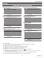
System Types
• Gas,oil,orelectricheatwithair
conditioning
• Warmair,hotwater,high
efficiency furnaces, heat
pumps, steam, gravity
• Heatonly—includingpowertoopen
and close zone valves (Series 20), and
normally open zone valves
• Heatonlywithfan
• Coolonly
• 750mVheatingsystems
This manual covers the TH8320ZW1000.
This thermostat contains a Lithium battery which may contain Perchlorate material.
PerchlorateMaterial—specialhandlingmayapply.
See www.dtsc.ca.gov/hazardouswaste/perchlorate
Need Help?
For assistance with this product please visit http://customer.honeywell.com
or call Honeywell Customer Care toll-free at 1-800-468-1502

Installation Guide
2
69-2486—03
M29481
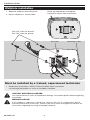
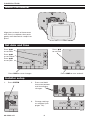
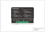
Wallplate installation
1. Separate wallplate from thermostat.
2. Mount wallplate as shown below.
MERCURY NOTICE
If this product is replacing a control that contains mercury in a sealed tube, do not
place the old control in the trash. Contact your local waste management authority for
instructions regarding recycling and proper disposal.
Grasptopandbottomofwallplate
and pull to remove from thermostat.
CAUTION: ELECTRICAL HAZARD
Can cause electrical shock or equipment damage. Disconnect power before beginning
installation.
Drill 3/16” holes for drywall.
Drill 7/32” holes for plaster.
Wallanchors
Wirehole Mounting screws
Must be installed by a trained, experienced technician
• Readtheseinstructionscarefully.Failuretofollowtheseinstructions
can damage the product or cause a hazardous condition.
+
+
+
M29480

TH8320ZW1000
3
69-2486—03
M32429
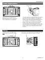
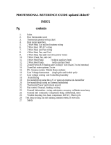
Power Requirements
Wiring
Connect the common side of
the transformer to “C” terminal.
This connection is mandatory.
Remove tab.
The thermostat is shipped from the factory
with the coin cell installed. To keep the
battery from discharging during shipment
and storage, the thermostat is shipped
with a plastic tab inserted in the battery
holder. This tab must be removed dur-
ing installation. Simply pull the plastic tab
out of the battery tray. Make sure that the
battery tray is fully inserted into the ther-
mostat.
Push excess wire back into the wall opening. Plug
wall opening with non-flammable insulation.
Remove factory-installed jumper
only for two-transformer systems.
M32431
K
K
M32430
K
K
M32428

Installation Guide
4
69-2486—03
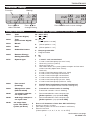
Wiring
See [notes] below
[1] Power supply. Provide disconnect means and overload protection as required.
[3] Connectionto24VACcommonatthetransformerisrequired.
[9] See"OptionalTHP9045WiringModule"on page 14 for more details.
Terminal Designations
Conventional Terminal Letters:
R Heating power. Connect to secondary
side of heating system transformer.
Rc Cooling power. Connect to secondary
side of cooling system transformer.
C Common wire from secondary side
of cooling transformer (if 2 transform-
ers).
W 1st stage heat relay.
W2 2nd stage heat relay
Y 1st stage compressor contactor.
Y2 2nd stage compressor contactor.
G Fan relay.
K OptionalTHP9045WiringModule
Terminal [9]
Heat Pump Terminal Letters:
R Heating power. Connect to secondary
side of heating system transformer.
Rc Cooling power. Connect to secondary
side of cooling system transformer.
C Common wire from secondary side of
cooling system transformer.
Y 1st stage compressor contactor.
Y2 2nd stage compressor contactor.
Aux Auxiliary heat relay.
G Fan relay.
E Emergency heat relay.
L Heat pump reset (powered continu-
ously when System is set to Em Heat;
system monitor when set to Heat,
Cool or Off).
O/B Changeover valve for heat pumps.
K OptionalTHP9045WiringModule
Terminal [9]
1H/1C System (1 transformer)
Rc Power [1]
R [R+Rc joined by jumper]
W Heat relay
Y Compressor contactor
G Fan relay
C 24VACcommon[3]
K OptionalTHP9045WiringModule
Terminal [9]
Heat Only System
Rc Power [1]
R [R+Rc joined by jumper]
W Heat relay
C 24VACcommon[3]
Heat Only System (Series 20)
Rc [R+Rc joined by jumper]
R Series 20 valve terminal “R” [1]
W Series 20 valve terminal “B”
Y Series20valveterminal“W”
C 24VACcommon[3]
2H/2C System (1 transformer)
Y2 Cool relay 2
W2 Heat relay 2
Rc Power [1]
R [R+Rc joined by jumper]
W Heat relay 1
Y Cool relay 1
G Fan relay
C 24VACcommon[3]
K OptionalTHP9045WiringModule
Terminal [9]
Wiring guide—conventional systems

TH8320ZW1000
5
69-2486—03
1H/1C Heat Pump (no auxiliary heat)
Rc Power [1]
R [R+Rc joined by jumper]
O/B Changeover valve [5]
Y Compressor relay
G Fan relay
C 24VACcommon[3]
K OptionalTHP9045WiringModule
Terminal [9]
2H/1C Heat Pump (with auxiliary heat)
L Equipment monitor [6, 7]
E Emergency heat relay [8]
Aux Auxiliary heat relay (Heat 2) [8]
Rc Power [1]
R [R+Rc joined by jumper]
O/B Changeover valve [5]
Y Compressor relay
G Fan relay
C 24VACcommon[3]
K OptionalTHP9045WiringModule
Terminal [9]
2H/2C Heat Pump (no auxiliary heat)
Y2 Compressor 2 relay
Rc Power [1]
R [R+Rc joined by jumper]
O/B Changeover valve [5]
Y Compressor 1 relay
G Fan relay
C 24VACcommon[3]
K OptionalTHP9045WiringModule
Terminal [9]
1H/1C System (2 transformers)
Rc Power (cooling transformer) [1, 2]
R Power (heating transformer) [1, 2]
W Heat relay
Y Compressor contactor
G Fan relay
C 24VACcommon[3,4]
K OptionalTHP9045WiringModule
Terminal [9]
Heat Only System With Fan
Rc Power [1]
R [R+Rc joined by jumper]
W Heat relay
G Fan relay
C 24VACcommon[3]
Cool Only System
Rc Power [1]
R [R+Rc joined by jumper]
Y Compressor contactor
G Fan relay
C 24VACcommon[3]
K OptionalTHP9045WiringModule
Terminal [9]
2H/2C System (2 transformers)
Y2 Cool relay 2
W2 Heat relay 2
Rc Power (cooling transformer) [1, 2]
R Power (heating transformer) [1, 2]
W Heat relay 1
Y Cool relay 1
G Fan relay
C 24VACcommon[3,4]
K OptionalTHP9045WiringModule
Terminal [9]
Wiring guide—heat pump systems
Wiring
See [notes] below
[1] Power supply. Provide disconnect means and overload protection as required.
[2] Remove jumper for 2 transformer systems.
[3] Connectionto24VACcommonatthetransformerisrequired.
[4] Common connection must come from cooling transformer.
[5] O/B set to control as either O or B in installer setup.
[6] If Lterminalisused,24VACcommon(terminalC)must be connected.
[7] Heat pump reset (powered continuously when thermostat is set to Em. Heat; system monitor
when set to Heat, Cool, or Off).
[8] Install field jumper between Aux and E terminals if there is no emergency heat relay.
[9] See"OptionalTHP9045WiringModule"on page 14 for more details.

Installation Guide
6
69-2486—03
SCHEDHOLD
TUE
FA N
AUTO
Inside
70
aM
6:00
SYSTEM
HEAT
DONE
20
0120
DONE CANCEL
aM
6:00
SYSTEM
HEAT
M32417
DONE
TUE
15
6
2006
DONE
TUE
PM
1:00
M29485
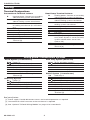
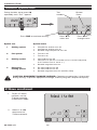
Align pins on back of thermostat
with slots in wallplate, then push
gently until thermostat snaps into
place.
Mount thermostat
Set date and time
Press st
to set time
Press st
to set date
Press st
to set month
Press st
to set year
Installer setup
Press DONE to save changes.
Press DONE to save and exit.
1. Press SYSTEM.
2. Press and hold
these two buttons
until the display
changes.
3. Change settings
as required (see
pages 7-9).
M32435

TH8320ZW1000
7
69-2486—03
DONE
20
0120
DONE
20
0120
M32427
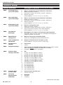
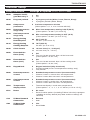
Installer setup
SettingFunction
Press DONE to exit & save settings.
Press st to
select function
Press st to
change setting
Setup functions Settings & Options (factory default in bold)
0120 Year
(rst two digits)
20 (2000-2078)
21 (2101-2178)
0130 Year
(second two digits)
10 (2010)
[Other options: 00-99]
0140 Month
6 [Other options: 1-12]
0150 Date
15 [Other options: 1-31]
0160 Schedule format
0 Nonprogrammable
4 Programmable
0165 Restore Energy
Saving Schedule
0 No
1 Yes
0170 System type
1 1 heat/1 cool conventional
2 1 heat/1 cool heat pump (no aux. heat)
3 Heat only (2-wire systems)
4 Heat only with fan
5 Hot water Series 20 system (power to open & close zone
valves/normally open zone valves)
6 Cool only
7 2 heat/1 cool heat pump (with aux. heat)
8 2 heat/2 cool multistage conventional
9 2 heat/1 cool multistage conventional
10 1 heat/2 cool multistage conventional
11 2 heat/2 cool heat pump (no aux. heat)
12 3 heat/2 cool heat pump (with aux. heat)
0180 Fan control
(heating)
0 Gas/Oil heat (equipment controls heating fan)
1 Electric furnace (thermostat controls heating fan)
0190 Changeover valve
(O/B terminal)
0 O terminal controls valve in cooling
1 B terminal controls valve in heating
0220 1st stage compres-
sor cycle rate
3 Recommended for most compressors
[Other options: 1, 2, 4, 5 or 6 CPH]
0230 2nd stage compres-
sor cycle rate
3 Recommended for most compressors
[Other options: 1, 2, 4, 5 or 6 CPH]
0240 1st stage heat
cycle rate (CPH =
cycles per hour)
5 Gas or oil furnaces of less than 90% efficiency
1 Steam or gravity systems
3 Hot water systems & furnaces of 90%+ efficiency
9 Electric furnaces
[Other options: 2, 4, 6, 7, 8, 10, 11, 12 CPH]
Continued on next page

Installation Guide
8
69-2486—03
Setup functions Settings & Options (factory default in bold)
0250 2nd stage heat
cycle rate (CPH)
5 Gas or oil furnaces of less than 90% efficiency
1 Steam or gravity systems
3 Hot water systems & furnaces of 90%+ efficiency
9 Electric furnaces
[Other options: 2, 4, 6, 7, 8, 10, 11, 12 CPH]
0260 3rd stage heat
cycle rate (CPH)
5 Gas or oil furnaces of less than 90% efficiency
1 Steam or gravity systems
3 Hot water systems & furnaces of 90%+ efficiency
9 Electric furnaces
[Other options: 2, 4, 6, 7, 8, 10, 11, 12 CPH]
0270 Emergency heat
cycle rate (CPH)
9 Electric emergency heat
1 Steam or gravity systems
3 Hot water systems & furnaces of 90%+ efficiency
5 Gasoroilfurnacesoflessthan90%efficiency
[Other options: 2, 4, 6, 7, 8, 10, 11, 12 CPH]
0280 Continuous
Backlight
0 Backlight on for approx. 45 seconds after keypress
1 Backlight always on low intensity, full bright after keypress
(requires24VACconnection)
0300 Manual/Auto
changeover
0 Manual changeover (Heat/Cool/Off)
1 Automatic changeover (Heat/Cool/Auto/Off)
0310 Auto changeover
deadband
3 Heat/cool temperature 3°F apart (1.5°C)
[Other options: 2-9 (2°F to 9°F/1°C to 5°C)])
0320 Temperature
display
0 Fahrenheit
1 Celsius
0330 Daylight savings
1 Auto-change to daylight savings time (through 2007, and for
areas that do not use the new 2008 DST calendar)
0 Daylight savings time is turned off
0500 Furnace lter
change reminder
0 Off
1 10-day run time (about 1 month)
2 30-day run time (about 3 months)
3 60-day run time (about 6 months)
4 90-day run time (about 9 months)
5 120-day run time (about 1 year)
6 180-day run time (about 1.5 years)
7 270-day run time (about 2 years)
8 365-day run time (about 3 years)
9 30 calendar days
10 60 calendar days
11 90 calendar days
12 120 calendar days
13 180 calendar days
14 365 calendar days
0502 Furnace lter
for Run time
0 Counts both heat and cool
1 Counts cool only
0520 UV Lamp
Replacement
Reminder
0 Disabled
1 365 days
2 730 days
Installer setup
Continued on next page

TH8320ZW1000
9
69-2486—03
Setup functions Settings & Options (factory default in bold)
0530 Adaptive Intelli-
gent Recovery™
1 On
0 Off
0540 Program periods
4 4 program periods (Wake, Leave, Return, Sleep)
2 2programperiods(Wake,Sleep)
0580 Compressor
protection
5 5 minute compressor off time
[Other options: 0, 1, 2, 3 or 4-minute off time]
0600 Heat temperature
range stop
90 Max. heat temperature setting is 90°F (32°C)
[Other options: 40-89°F (4°C to 32°C)]
0610 Cool temperature
range stop
50 Min. cool temperature setting is 50°F (10°C)
[Other options: 51-99°F (11°C to 37°C)]
0615 Energy Saving
Heat Setpoint
65 65°F (18.5°C)
40-90°F (4.5°C to 32°C)
0616 Energy Saving
Cooling Setpoint
78 78°F (25.5°C)
50-99°F (10°C to 37°C)
0640 Clock format
12 12-hour time (i.e., “3:30 pm”)
24 24-hour time (i.e., “15:30”)
0650 Extended fan
timer (heat)
0 Off
90 Fan runs for 90 seconds after call for heat ends
[Other options: 30, 60, 120]
0660 Extended fan
timer (cool)
0 Off
90 Fan runs for 90 seconds after call for cooling ends
[Other options: 30, 60, 120]
0670 Keypad lock
0 Keypad unlocked (fully functional)
1 Partially locked (access to temperature settings only)
2 Fully locked
0680 Heat temperature
control
2 Standard temperature control (recommended)
1 Choose if room is warmer than set temperature
3 Choose if room does not reach set temperature
0690 Cool temperature
control
2 Standard temperature control (recommended)
1 Choose if room is cooler than set temperature
3 Choose if room does not reach set temperature
0700 Temperature
display offset
0 Thermostat displays actual room temperature
[Other options: -3, -2, -1, 1, 2, 3°F offset (-1.5°C to 1.5°C)]
0710 Reset
0 No reset
1 Resetinstalleroptions(includingZ-Waveinclusion)&program
schedule to factory default (only date and time settings are
retained)
rf10 Z-Wave Network
Connection
0 Remove
1 Add
rf20 Z-Wave Node
Connection
0 Idle
1 Send Node
Installer setup

Installation Guide
10
69-2486—03
DONE
20
0120
DONE
1
0
TEST
M29488
During installer setup, press t
repeatedly until “Test” appears.
Test
number
System
status
Press t to
select test
Press t to
change status
Press DONE to terminate testing.
1 Cooling system
0 Compressor and fan turn off
1 Compressor and fan turn on
2 Second stage compressor turns on
2 Fan system
0 Fan turns off
1 Fan turns on
3 Heating system
0 Heat and fan turn off
1 Heat turns on (fan on if Function 0170 is set for heat pump,
or if Function 0180 is set to “1”)
2 Second stage heat turns on
4 Emergency
heating system
0 Em Heat and fan turn off
1 Em Heat and fan turn on
2 Second stage heat turns on (Auxiliary heat)
System test System status
CAUTION: EQUIPMENT DAMAGE HAZARD. Compressor protection is bypassed
during testing. To prevent equipment damage, avoid cycling the compressor quickly.
Installer system test
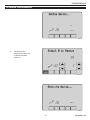
Z-Wave enrollment
1. TojoinaZ-Wave
network, set the
Z-Wavecontroller
to INCLUDE mode.
2. Select 1 to add
thermostat to
Z-Wavenetwork.
DONE
0
F
M32423A
10

TH8320ZW1000
11
69-2486—03
F
M32422
10
Wait
3. To remove the
thermostat from the
Z-Wavenetwork
select 0.
Z-Wave enrollment
F
M32425
10
DONE
1
F
M32424A
10
14

Installation Guide
12
69-2486—03
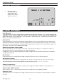
Z-Wave enrollment
4. To share the
thermostat Node
information with
additionalZ-Wave
devices select 1.
DONE
0
F20
M32421
Z-Wave messages
Add/ Remove
ThethermostatcanbeincludedorexcludedfromtheZ-Wavenetwork.Thisactionrequiresthe
controllersetininclusionmode.ThedeviceisincludedtotheZ-Wavenetworkaftersendingthe
node information to the controller. The controller is responsible for assigning the home ID and
device ID to the included device.
Association
The thermostat can be associated with other devices in the system. Being associated means
that the thermostat is able to send messages directly to any other device. During the associa-
tion process the return route is acquired from the primary controller. The thermostat then uses
this return route to access the distant node.
Enter/leave power saving mode
WhenrequestedfromtheZ-Wavecontroller,thethermostatadjustsitssetpointinorderto
decreasethepowerconsumptionoftheHVACequipment.
In addition, using an Internet gateway enables the person to control the thermostat remotely
through the Internet.
Fan Switch
The thermostat can send the message containing the actual fan switch position.
Fan Switch change
The other devices are able to change the fan switch of the thermostat. After the message is
received, the fan switch is changed to the desired value (if this value is possible).
For the thermostat the possible values are On, Auto and Circ.
Indoor temperature
The thermostat sends the indoor temperature using the Multilevel Sensor command class.
Report upon GET request
Uponrequest(GETcommand)thethermostatsendsthecorrespondingreport.
Setpoint Value
The thermostat can send the message containing the actual setpoint value based on setpoint
change.

TH8320ZW1000
13
69-2486—03
Z-Wave messages
Setpoint change
OtherZ-Wavedevicesareabletomodifythesetpointofthethermostat.Theabsolutevaluecan
be sent by the controller and thermostat will change the setpoint to this value.
System Switch
The thermostat can send the message containing the actual system switch based on system
switch change.
System switch change
Other devices (controllers) are able to change the system switch of the thermostat. After the
message is received by the thermostat, the system switch is changed to desired value (if this
value is seven).
Seven possible switch modes are available for the thermostat: Heat / Cool / Off / Auto / Energy
Saving Heat / Energy Saving Cool / Em Heat. The number of allowed system switch selection
depends on the actual configuration of the thermostat. The thermostat uses "Thermostat Mode
Supported" report command class to tell other devices the actually supported system switch
modes.
Thermostat Fan State
The thermostat can send the message containing the actual state of fan based on fan state
change. The Fan state can be either "Auto" or "On".
Thermostat Operating State
ThethermostatcansendthemessagecontainingtheactualstateoftheHVACequipment
based on equipment state change.
The thermostat provides the following operating states:
• Idle-noequipmenton
• Heating-heatingequipmenton
• Cooling-coolingequipmenton
• PendingHeat-minimumofftimeappliedtoprotecttheheatpumpcompressor
• PendingCool-minimumofftimeappliedtoprotecttheheatpumpcompressor
Time/Date
The thermostat can send the message containing the actual Time and Date.
Time/Date change
The time and date is able to be changed on the thermostat. After the report is received, the time
and/or date is changed to the desired value (if this value is possible).
Unsolicited Report Message
Sending the message is possible only if the thermostat is associated with any other node. The
thermostat will send the message using assigned node ID and return route.

Installation Guide
14
69-2486—03
Special functions
Auto Changeover(SetupFunction0300):WhensettoAuto,thethermostatautomaticallyselects
heating or cooling depending on the indoor temperature. Heat and cool settings must be at least 2
degrees apart.
Adaptive Intelligent Recovery (Setup Function 0530): Allows the thermostat to “learn” how long
the furnace and air conditioner take to reach programmed temperature settings, so the temperature is
reached at the scheduled time.
Compressor Protection (Setup Function 0580): Forces the compressor to wait a few minutes before
restarting,topreventdamage.Duringthistime,themessage“Wait”isonthedisplay.
TheTHP9045WiringModuleisdesignedtobeusedwithapplicablethermostatsin1Heat/1
Cool retrofit applications where only 4 wires are available. The K terminal on the thermostat can
be used to operate both the fan and compressor on a single wire, and the module is designed to
receive the signal from the K terminal, split that signal and reroute it to operate the compressor,
and/or fan for normal operation. See the THP9045 manual for further details.
Optional THP9045 Wiring Module
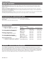
Temperature Ranges
• Heat:40°to90°F(4.5°to32°C)
• Cool:50°to99°F(10°to37°C)
Operating Ambient Temperature
• 0°to120°F(-18°to48.9°C)
Shipping Temperature
• -30°to150°F(-34°to66°C)
Operating Relative Humidity
• 5%to90%(non-condensing)
Physical Dimensions
• 4-23/25”Hx6-2/5”Wx1-19/46”D
• 125mmHx166mmWx36mmD
Electrical Ratings
Terminal Voltage(50/60Hz) RunningCurrent
WHeating 20-30Vac 0.02-1.0A
(Powerpile) 750mVDC 100mADC
W2Heating 20-30Vac 0.02-0.6A
YCooling 20-30Vac 0.02-1.0A
Y2Cooling 20-30Vac 0.02-0.6 A
AuxAuxiliaryheat 20-30Vac 0.02-1.0A
O/BChangeover 20-30Vac 0.02-0.6A
EEmergencyheat 20-30Vac 0.02-1.0A
LHeatpumpreset 20-30Vac 0.02-0.6A
Specifications
Please contact your distributor to order replacement parts.
Cover plate* ............................................................ Part Number 32003796-001
*(Use to cover marks left by old thermostats.)
Accessories & replacement parts

TH8320ZW1000
15
69-2486—03
Regulatory information
FCC Compliance Statement (Part 15.19) (USA only)
This device complies with Part 15 of the FCC Rules. Operation is subject to the following two
conditions:
1) This device may not cause harmful interference, and
2) This device must accept any interference received, including interference that may cause
undesired operation.
FCC Warning (Part 15.21) (USA only)
Changes or modifications not expressly approved by the party responsible for compliance
could void the user’s authority to operate the equipment.
FCC Interference Statement (Part 15.105 (b)) (USA only)
This equipment has been tested and found to comply with the limits for a Class B digital device,
pursuant to Part 15 of the FCC Rules. These limits are designed to provide reasonable protec-
tion against harmful interference in a residential installation. This equipment generates, uses,
and can radiate radio frequency energy and, if not installed and used in accordance with the
instructions, may cause harmful interference to radio communications. However, there is no
guarantee that interference will not occur in a particular installation. If this equipment does
cause harmful interference to radio or television reception, which can be determined by turning
the equipment off and on, the user is encouraged to try to correct the interference by one of the
following measures:
• Reorientorrelocatethereceivingantenna.
• Increasetheseparationbetweentheequipmentandreceiver.
• Connecttheequipmentintoanoutletonacircuitdifferentfromthattowhichthereceiveris
connected.
• Consultthedealeroranexperiencedradio/TVtechnicianforhelp.
Section 7.1.2 of RSS-GEN
Under Industry Canada regulations, this radio transmitter may only operate using an antenna of
a type and maximum (or lesser) gain approved for the transmitter by Industry Canada. To reduce
potential radio interference to other users, the antenna type and its gain should be so chosen that
the equivalent isotropically radiated power (e.i.r.p.) is not more than that necessary for successful
communication.
Section 7.1.3 of RSS-GEN
This Device complies with Industry Canada License-exempt RSS standard(s). Operation is sub-
ject to the following two conditions: 1) this device may not cause interference, and 2) this device
must accept any interference, including interference that may cause undesired operation of the
device.

Honeywell International Inc.
1985 Douglas Drive North
GoldenValley,MN55422
http://customer.honeywell.com
Automation and Control Solutions
® U.S. Registered Trademark.
US Patent No. 6,574,581, 6,975,958, 7,114,554,
7,346,467, 7,636,604, 7,693,582, 7,788,936, 7,845,576,
and other patents pending.
© 2011 Honeywell International Inc.
69-2486—03M.S.Rev.05-11
Printed in U.S.A.
Honeywell Limited-Honeywell Limitée
35 Dynamic Drive
Toronto,OntarioM1V4Z9
Z-WaveisaregisteredtrademarkofZensys,Inc.and/oritssubsidiaries.
-
 1
1
-
 2
2
-
 3
3
-
 4
4
-
 5
5
-
 6
6
-
 7
7
-
 8
8
-
 9
9
-
 10
10
-
 11
11
-
 12
12
-
 13
13
-
 14
14
-
 15
15
-
 16
16


Honeywell Thermostat TH8320ZW1000 User manual
- Category
- Thermostats
- Type
- User manual
- This manual is also suitable for
Ask a question and I''ll find the answer in the document
Finding information in a document is now easier with AI
Related papers
-
Honeywell TH8320ZW Installation guide
-
-
Honeywell 8000 User manual
-
Honeywell T8411R User manual
-
-
-
-
-
-
Other documents
-
Bard 8403-058 User manual
-
Trane TCONT600AF11MA Installation Instructions Manual
-
 Founten FS-STAT-32AC Installation guide
-
-
-
 RainMachine SPK3-16 Installation guide
-
Ecolink Z-Wave Smart Thermostat User manual
-
 RiteTemp 6035 User guide
-
 Honeywell Home TH6320ZW2003/U User guide
-
WarmlyYours TH8321WF1001 Installation guide


