Page is loading ...

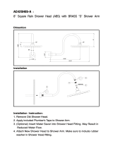
Dimensions are for reference.
Thank you for selecting American-Standard...the benchmark of fine
quality for over 100 years.
To ensure that your installation proceeds smoothly--please read these
instructions carefully before you begin.
ROUGHING-IN DIMENSIONS
Installation for Bath/Shower,
Shower only, or Valve only Trim.
Certified to comply with ANSI A112.18.1
M968289
Installation
Instructions
1
INSTALL
TRIM
When finished tiling the wall, remove PLASTER GUARD (A)
and turn off water supply.
Push CAP (1) over VALVE CARTRIDGE (2).
Mount ESCUTCHEON (3) to valve body with SCREWS (4).
Push DIAL PLATE (9) over CAP (1) and into the three alignment holes
in ESCUTCHEON (3).
Remove PIPE CAP (5) and PIPE PLUG (9) from shower pipe and
tub filler pipe.
Install SHOWER ARM (6), SHOWER HEAD (7) and TUB FILLER SPOUT
(8) by threading onto pipe nipples using teflon tape or pipe sealant.
Install HANDLE (10) onto CARTRIDGE STEM (11). Tighten SET SCREW (12)
with HEX WRENCH (13) supplied with fitting to secure HANDLE (10).
Push INDEX BUTTON (14) into set screw opening in HANDLE (10).
CAUTION: Protect finish on SHOWER ARM,
SHOWER HEAD and TUB SPOUT when installing.
BATH/SHOWER
TRIM KITS
T6280
T6281
T6282
FINISHED WALL
4"
BOTTOM OF TUB
74" FOR HEAD
CLEARANCE
5-1/8" REF.
7-1/2" REF.
18" OPTIONAL
5-5/8" REF.
1/2" NPT
1/2" NPT
7-1/8"
1" MIN.
TOP OF TUB RIM
by
COLLECTION
™
“”
THE
CARE INSTRUCTIONS:
DO: SIMPLY RINSE THE PRODUCT CLEAN WITH
CLEAR WATER. DRY WITH A SOFT COTTON
FLANNEL CLOTH.
DO NOT: CLEAN THE PRODUCT WITH SOAPS,
ACID, POLISH, ABRASIVES, HARSH CLEANERS,
OR A CLOTH WITH A COARSE SURFACE
Required Tools
Flat Blade Screwdriver
Adjustable Wrench
Channel Locks
Plumbers' Putty or Caulking
Phillips Screwdriver
6
7
3
1
11
9
2
A
5
8
9
4
10
(3) ALIGNMENT
HOLES FOR
DIAL PLATE
13
14
12

2
Remove HANDLE and TRIM. See step one and reverse assembly procedure.
TO GAIN ACCESS TO VALVE FOR SERVICING
Remove CARTRIDGE (1) by removing CARTRIDGE SCREWS (2). Remove three SCREWS (3) from FIXATION RING (4) and
pull out PRESSURE BALANCING (5) unit.
Clean SEALS (9) on base of CARTRIDGE (1). Check base of PRESSURE BALANCING UNIT (5) and clean O-RINGS (6). Remove
CAPS (7) and check O-RINGS on inside of CAPS (7) for debris. Clean inside sealing surfaces of VALVE BODY (8).
Reassemble PRESSURE BALANCING UNIT (5) and CARTRIDGE (1). Tighten all screws.
Turn on water supply. If it still leaks, replace pressure balancing unit (M952100-0070A). See step one for installing
TRIM and HANDLE.
VALVE LEAKS WHEN SHUT OFF
Remove PRESSURE BALANCE UNIT (5).
Remove CAPS (7) and clean valve thoroughly.
Examine balancing unit and check condition of O-ring on end of piston. Piston should move back and forth. Order Repair
Part M952100-0070A if balancing unit is defective.
Replace CAPS (7) and install PRESSURE BALANCE UNIT (5). Make sure inlets line up with two holes in bottom of casting.
Top flange should butt-up against top of casting.
UNABLE TO MAINTAIN CONSTANT TEMPERATURE
M968289
TEST INSTALLED FITTING
4
Turn VALVE (1) "off".
With HANDLE (2) in "off" position, turn
on water supplies and check all connections
for leaks.
Operate HANDLE (2) and flush water
lines thoroughly. Pull DIVERTER (3) up
and check SHOWER (4) for proper
operation.
Check SPOUT (5) and SHOWER (4)
connections for leaks.
1
2
3
4
5
6
7
8
9
HANDLE and TRIM
ADJUST HOT LIMIT STOP
3
1
3
2
4
"B""A"
ADJUSTMENT WHEN
WATER IS TOO HOT
PRY OUTWARD TO UNLOCK AND
ROTATE
COUNTER- CLOCKWISE
ONE CLICK.
ADJUSTMENT WHEN
WATER IS TOO COLD
PRY OUTWARD TO UNLOCK
AND ROTATE
CLOCKWISE
ONE CLICK.
By restricting HANDLE rotation and limiting the
amount of hot water allowed to mix with the cold, the
HOT LIMIT SAFETY STOP (1) reduces risk of accidental
scalding. To set the maximum hot water temperature
of your faucet, all you need to do is adjust the setting
on the HOT LIMIT SAFETY STOP (1).
Remove PLUG BUTTON (2). Loosen HANDLE SCREW (3)
and pull off HANDLE (4).
Replace CARTRIDGE CAP (5) and HANDLE (4). Tighten
HANDLE SCREW (3). Replace PLUG BUTTON (2).
Pull off CARTRIDGE CAP (5).
See "A" and "B" for HOT LIMIT STOP (1) adjustment.
5
1
1
1
2
3
5
4

MODEL NUMBER
M968289
BATH/SHOWER
M962167-YYY0A
ESCUTCHEON AND SCREWS
M907050-YYY0A
ESCUTCHEON CAP SET
078016-YYY0A
ESCUTCHEON SCREWS
M953575-YYY0A
SHOWER HEAD
M909659-0070A
DIAL PLATE
M953415-YYY0A
DIVERTER SPOUT (IPS)
M907557-YYY0A
TUB SPOUT
ESCUTCHEON
M962168-0070A
DIVERTER SPOUT
REPAIR KIT
060351-YYY0A
SHOWER ARM AND FLANGE
by
COLLECTION
™
“”
THE
CHROME
SATIN
002
295
Replace the "YYY" with
appropriate finish code
HOT LINE FOR HELP
For toll-free information and answers to your questions, call:
1-800 442-1902
Weekdays 8:00 a.m. to 8:00 p.m. EST
IN CANADA 1-800-387-0369 (TORONTO 1-905-306-1093)
Weekdays 8:00 a.m. to 7:00 p.m. EST
Product names listed herein are trademarks of American Standard Inc.
© American Standard Inc. 2003
T6280
T6281
T6282
M962240-YYY0A
INDEX HANDLE KIT
M962241-YYY0A
HANDLE KIT
/