Page is loading ...

the E-E/H programming mode as follows:
• EnterReverseModebypressingtheBoostButton
for5secondswhilethebrakepedalispresseduntil
[
.r
]
displayed.
• Whilecontinuingtohavethebrakepedalpressed,
momentarilyreleasetheBoostButtonforlessthan
onesecondandthenpressandcontinuetoholdthe
boostbuttondownforanadditional5seconds.
• Thedisplaywillnowchangefromtheboostvalue
to a flashing
[
E.
]
or
[
E.H
]
.Depressandrelease
Boostrepeatedlytoselectthedesiredmode.
• EngagetheManualKnobtoacceptthemode,or
wait10secondsforthefunctiontoautomatically
timeoutandacceptthemode.Themodeselected
willbestoredinmemoryevenwhendisconnected.
WheninElectricoverHydraulicmode,thedisplay
will change to
[
.C
]
and
[
n.C
]
.Theupper-case
“C” indicated E/H rather than the lower case “c” for
Electricmode.
(Réglage de la suralimentation – Suite)
Lorsque la suralimentation est au niveau 2, [
b
.2
],
ou lorsque la suralimentation est au niveau 3, [
b
.3
],
durantunévénementdefreinage,lapuissancedémarre
automatique-mentàenviron28%duréglagedepuis-
sanceetelleaugmenteavecladécélération.
Quelquescasoùl’utilisationduboutondesuralimenta-
tionpourraitêtresouhaitable:
• Onveutquelefreinagedelaremorque«GUIDE»
levéhiculederemorquage.
• Remorquageàpleinechargeparrapportau
remorquageàvide.
• Dégradationdelaperformancedefreinage(la
majoritédesfreinsélectriquesdoiventêtreréglés
manuellement–voirl’annexeAouconsulterle
concessionnairedanslecasd’unréglageoud’une
réparation).
REMARQUE :Ledispositifdesuralimention
n’estpasconçupourremplacerleréglageoula
réparationdesfreins.
Consulterletableauci-dessouspourconnaîtreles
réglagesdesuralimentationrecommandés(identifiéspar
unX)enregarddesrelationstypiquesentrelepoidsde
laremorqueetlepoidsduvéhicule.
Sélectionnerleréglagedelasuralimentationenfonc-
tiondessituationsderemorquageparticulières,des
préférences
enmatièredeconduiteetdel’étatdesfreins
delaremorque.
Prodigy
®
P2
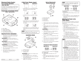
Commande électronique de frein
Pour applications de 2, 4, 6 et 8 freins
LISEZ CECI EN PREMIER :
Ilimportedelireoudesuivreattentivementtoutes
lesconsignesavantdeposeroud’utiliserla
commandedefreinProdigyP2.Cesconsignesdoi-
ventêtreconservéesaveclacommandedefreinpour
consultationfuture.
Composants de la commande de frein
A.Boutondepuissance
B.Boutondesuralimentation
C.Boutonmanuel
D.Connecteur(pourfaisceaudefils)
E.Troudemontage(1parcôté)
Faits importants à garder en mémoire
1. Nepasmonterniactionnerdesappareilsprodui-
santdesHF(téléphonescellulaires,radiosbidirec-
tionnelles)àproximité(moinsde12po)dela
commandedefrein.
2. LacommandedefreinProdigyP2utiliseun
capteurinertiel.Elledétecteladécélérationet
produitunesortiebaséesurladécélération,d’où
l’expression«freinageproportionnel».
3. LacommandedefreinProdigyP2
«RETIENDRA»laremorqueavec25%du
réglagedepuissanceàl’étatstatiqueavecla
pédaledefreinenfoncéedurantaumoins5sec-
ondes.
4. LacommandedefreinProdigyP2actionnerales
freinsproportionnellementenmarchearrière.
Elleappliqueralatensionélectriqueappropriée
enfonctiondeladécélération.
5. Pourassistancetechniqueetinformationsconcer-
nantlagarantie,prièred’appelerle1-888-785-
5832ouwww.tekonsha.com.
6. AVERTISSEMENT:Lepoidsnominalbrut
combiné(PNBC)nedoitjamaisdépasserlepoids
recommandéparlefabricantduvéhicule.
(Boost Setting continued)
[
b
.I
], duringabrakingevent,thepowerautomatically
startsoutatapproximately14%ofthepowersettingand
increaseswithdeceleration.With the boost on level 2,
[
b
.2
], or with the boost on level 3,[
b
.3
], during
abrakingevent,thepowerautomaticallystartsoutat
approximately28%ofthepowersettingandincreases
withdeceleration.
Somecaseswhereyoumightwanttousetheboostbutton:
• Youlikethetrailerbrakingto‘LEAD’thetow
vehicle’sbraking
• Towingafullvs.emptytrailer
• Degradedbrakeperformance(mostelectricbrakes
requiremanualadjustment-seeAppendixAora
dealerforadjustmentorrepair)
NOTE:Boostnotintendedtobeusedtotakeplaceof
trailerbrakeadjustmentorrepair.
Seethechartbelowforrecommended“Boost”settings
(indicatedwithX)fortypicalTrailertoVehicleweight
relationships.
Selectyourboostsettingbasedonyourtowingsituation,
drivingpreferenceandconditionofyourtrailerbrakes.
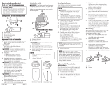
Installation Guide
TheProdigyP2canbemountedfrom0degreesto
360degreesverticallyinthedirectionoftravel.(See
DiagramforMounting the Prodigy P2).
FailuretoinstalltheProdigyP2withinthesecon-
straintsmaycauseimpairedperformance.
Wiring Brake Control
YourProdigyP2brakecontrolhasaunique
connectorlocatedatthebackofthecontrol.This
connectorallowsyoutwooptionstowireyourbrake
control.
Option 1:
UsePigtailWiringHarnessincluded.Thisharnesscan
beinstalledbyfollowingtheGenericWiringGuide.
Option 2:
Useavehiclespecificwiringharness.Ifyourvehicle
camewithafactorytowpackagethatincludeda7-way
connector,youcanpurchaseaTekonshaOEMwiring
harnesswiththeProdigyP2connectorononeendand
yourspecificvehicle’sconnectorontheother.
Display Readings after Wiring the Prodigy P2
AftersuccessfullywiringyourProdigyP2youshould
seethefollowingonthetwo-digitdisplay:
• PowertoProdigyP2withouttrailerconnected.
• PowertoProdigyP2withtrailerconnectedand
• ManualKnobActivatedwithouttrailer
• Manualknobactivated(withtrailer),5.4denotesa
hypotheticalpoweroutput.Thisvalueissetusing
thepowerknob.Rangeis0.0to13volts.Thisis
anindicationofvoltageoutputtoelectricbrakes.
• PowertoProdigyP2butdisplayisinpowersaving
mode(nomotionoractivityforatleastfifteen
minutes).
Mounting the Prodigy P2
Traditional Bracket Mount
A. MountingBracket
B. #8 X 3/8" Machine Screw with Internal Tooth
Washer
1. CAUTIONDrillingoruseoflongerscrewsmay
damageunit.
2. Securelymountbrackettoasolidsurface.
3. Insertsupplied#8 x 3/8" machine screws on each
sideintothemountingholes.
4. Adjustcontroltodesiredpositionandtighten
screwsuntilsnug.
Under Dash Pocket Mount
A. PocketMount
B. #6X1/2"SelfTappingScrews
1. SecurelymountPocket Mounttoasolidsurface
usingsupplied#6X1/2"SelfTappingScrews.
2. InsertProdigyP2Brakecontrol.
3. Pluginconnector.
NOTE:
1. FrontoftheProdigyP2mustbehorizontal(+_20
degrees),see below.
2. TheProdigyP2mustbeparalleltodirectionof
travel(+_20degrees),see below.
Automatic Leveling of the Sensor
TheProdigyP2willautomaticallyacquiretheproper
levelsetting.Itwillalsoautomaticallyadjustasyou
travelupordownhills.
Adjusting the Power to the Trailer
Brakes
(Prior to setting Boost)
Oncethecontrolhasbeensecurelymountedinthe
directionoftravel,itisnecessarytosetthepower
neededtostopthetrailerduringabrakingevent.
1. Connecttrailertotowvehicle.
2. Withenginerunningholdmanualfullleftandset
PowerKnobtoindicateapproximately6.0
3. Drivetowvehicleandtraileronadrylevelpaved
surfaceat25mphandfullyapplymanualknob.
3 Iftrailerbrakeslockup:
q Turnpowerdownusingpowerknob.
3 Ifbrakingwasnotsufficient:
q Turnpowerupusingpowerknob.
4. RepeatStep(3)untilpowerhasbeensettoapoint
justbelowwheellockuporatasufficientforceas
toachievemaximumbrakingpower.
5. Usingthebrakepedal,makeafewlowspeed
stopstocheckthepowersetting.Trailerbraking
isinitiatedandterminatedviathestoplightswitch.
Whenthebrakepedalisreleased,trailerbraking
willcease.
360˚
0˚
Di re ct io n of Trav el
Di re ct io n of Trav el
Correct
Incorrect
P/N120065-006 REVA 11/09
Reverse
Whenbackingatraileryoucancancel“BOOST”and
“HOLD”foraperiodofthreeminutes.Thiscanbe
accomplishedbypressingtheboostbuttoncontinu-
ouslyforfivesecondswiththebrakepedaldepressed.
Thedisplaywillindicate:
(If“boost”wasactive,therighthanddecimalpoint
willalsobeon.)Afterthreeminutesthe“BOOST”and
“HOLD”featureswillautomaticallyreturntoyour
previoussettings.
NOTE:
Returningtoyourprevioussettingspriortothreemin-
utescanbeaccomplishedbypressingtheboostbutton.
T y p i c a l Boost S e t t i n g s For O p t i m a l Performance
(with properly adjusted trailer brakes*)
TRAILER WEIGHT compared to VEHICLE WEIGHT
Trailer weighs LESS than Vehicle
Trailer weighs APPROXIMATELY SAME as Vehicle
Trailer weighs UP TO 25% MORE than Vehicle
Trailer weighs UP TO 40% MORE than Vehicle
Trailer weighs OVER 40% MORE than Vehicle
X X
X X X
X X X
X X
X
WARNING
Do not exceed Gross
Combined Weight Rating (GCWR)
* Increased Boost setting may be needed if trailer brakes are worn, see Appendix A or a dealer for brake adjustment or repair
.
INCREASING BOOST LEVEL
➮
BOOST “OFF”
Boost Setting
Theboostbuttonwasdesignedtoallowamoreaggressive
settingforyourtrailerbrakesandisavailableinthreelev-
els - [
b
.I
],[
b
.2
],[
b
.3
].Eachincrementalboostsetting
increasesthesensitivityoftheProdigyP2’sinertialsen-
sor,enhancingthepaticipationofthetrailerbrakesduring
abrakingevent.
Thefirstpressontheboostbuttondisplaysthecurrentset-
ting.Boostisadvancedtothenextlevelbycontinuingto
presstheboostbutton.
Fivesecondsaftersettingtheboostlevel,thedisplaywill
show
indicating Boost Onbytherightmostdecimal.
For example: With the boost off,[
b
.
], duringabrak-
ingevent,thepowertothebrakesstartsoutatzeroand
increaseswithdeceleration.With the boost on level 1,
Boost On
3. Thepowermayneedtobeadjustedfordifferent
loadweightsandroadconditions.
4. Notalltrailerbrakeswilllockupduetovarious
conditions.However,inabilitytolockupthe
brakesgenerallyindicatestheneedforaninspec-
tiontodeterminethecause.
5. Whenthepowerissetcorrectlyyoushould
feelunifiedbrakingbetweenthetrailerandtow
vehicle.
NOTE:
1. Alwayswarmthetrailer’sbrakesbefore
settingthepower.Warmtrailerbrakestendto
bemoreresponsivethancoldbrakes.Towarm
trailerbrakes,driveashortdistance(1/4mile)at
45MPHwithmanualleverengagedenoughto
causetrailerbrakingatalowlevel.
2. WARNINGThepowershouldneverbeset
highenoughtocausetrailerbrakestolockup.
Skiddingtrailerwheelscancauselossofdirec-
tionalstabilityoftrailerandtowvehicle.
Guide d’installation
LeProdigyP2peutsemonterde0à360degrésver-
ticalementdansladirectiondudéplacement.(Voirle
SchémademontageduProdigyP2).
LedéfautdeposerlacommandedefreinProdigyP2
àl’intérieurdecescontraintespeutaltérerla
performance.
Câblage de la commande de frein
LacommandedefreinProdigyP2estdotéed’un
nouveauconnecteuruniquesituéàl’arrièredelacom-
mande.Ceconnecteurestoffertavecdeuxoptionspour
câblerlacommandedefrein.
Option 1:
Utiliserlefaisceaudefilsenroulésquiestinclus.
Cefaisceaupeutêtreposéenconsultantleguidede
câblagegénérique.
Option 2:
UtiliserlefaisceaudefilsspécifiquedeFord,Dodge
ouGM.Siunensemblederemorquaged’usinecom-
prenantunconnecteurà7voiesétaitfourniavecvotre
véhicule,vouspouvezacheterunfaisceaudefils
OEMTekonshamuniduconnecteurProdigyP2àune
extrémitéetduconnecteurspécifiqueàvotrevéhiculeà
l’autreextrémité.
Affichage des mesures après le câblage de la com-
mande Prodigy P2
Aprèsavoirréussilecâblagedevotrecommandede
freinProdigyP2,vousdevriezapercevoirleséléments
suivantssurl’afficheuràdeuxchiffres:
• L’alimentationserendàlacommandeProdigyP2
etlaremorquen’estpasattelée.
• CourantentreProdigyP2etlaremorquebranchéet
• Leboutonmanuelestactivéetlaremorquen’est
pasattelée.
• Leboutonmanuelestactivé(aveclaremorque),
5.4représenteunepuissancedesortiehypothé-
tique.Cettevaleurestrégléeàl’aideduboutonde
puissance.Lafourchettedevaleurss’étendde0.0
à13volts.Ils’agitd’uneindicationdelatesionde
sortieauxfreinsélectriques.
• CourantàProdigyP2,maislecadranestenmode
économie(aucunmouvementouactivitépendant
aumoinsquinzeminutes).
Montage de la commande de frein Prodigy P2
Montage traditionnel du support
A. Supportdemontage
B. VisdemécaniqueNo.8x3/8poavecrondelleà
cransintérieurs
1. ATTENTION:Leperçageoul’utilisationdevis
pluslonguespeutendommagerl’unité.
2. Montersolidementlesupportsurunesurface
ferme.
3. InsérerlesvisdemécaniqueNo.8x3/8podans
lestrousdemontagedechaquecôté.
4. Réglerlacommandeàlapositiondésiréeetserrer
lesvisfermementmaisnonexcessivement.
Montage dans un logement
sous le tableau de bord
A. Logement
B. VisautotaraudeuseNo.6x1/2po
1. Montersolidementlelogementsurunesurface
solideàl’aidedesvisautotaraudeusesNo. 6 x 1/2
po.
2. InsérerlacommandedefreinProdigyP2.
3. Brancherleconnecteur.
REMARQUE :
1.LedevantdelacommandedefreinProdigyP2
doitêtrehorizontal(+_20degrés),voir ci-après.
2.LacommandedefreinProdigyP2doitêtreparallèle
ausensdemarche(+_20degrés),voir ci-après.
Mise à niveau automatique du capteur
LamiseàniveaudelacommandedefreinProdigyP2
s’effectueraautomatiquementdelamanièreappropriée.
Lamiseàniveaus’ajusteraaussiautomatiquement
lorsquevouscirculerezsurunterrainaccidenté.
Se ns d e ma rc he
Se ns d e ma rc he
Correct
Incorrect
Réglage de la suralimentation
Leboutondesuralimentationaétéconçudanslebutde
permettreunréglageplusagressifdesfreinsdela
remorqueetilestdisponibleselontroisniveaux-[
b
.I
],
[
b
.2
],[
b
.3
].Chaqueaugmentationduréglagedela
suralimentationaccroîtlasensibilitéducapteurinertiel,
intensifiant ainsi la participation des freins de la
remorquelorsd’unévénementdefreinage.
Lapremièrepressionsurleboutondesuralimentation
montreleréglageactuel.Lasuralimentationpasseau
niveausuivantquandoncontinueàpressersurlebouton
desuralimentation.
Cinqsecondesaprèsleréglageduniveaudesuralimenta-
tion,
l’affichageindiqueraBoost On (alimentation ouverte)
enallumantladécimalesituéeàl’extrêmedroite.
Par exemple : Lorsque la suralimentation est fermée
[
b
.
]
durantunévénementdefreinage,lapuissanceaux
freinsdémarreàzéroetelleaugmenteavecladécéléra-
tion.Lorsque la suralimentation est au niveau 1 durant
un[
b
.I
] événementdefreinage,lapuissance
démarreautomatiquementàenviron14%duréglagede
puissanceetelleaugmenteavecladécélération.
Boost On
alimentation
ouverte
Réglage de la puissance aux freins
de la remorque
(Avant le réglage de la sur-
alimentation)
Unefoislacommandefermementmontéedansla
directiondudéplacement,ilfautréglerl’alimentation
électriquenécessairepourarrêterlaremorquelorsd’un
événementdefreinage.
1. Raccorderlaremorqueauvéhiculederemor-
quage.
2. Lemoteurenmarche,maintenirleboutonManual
(manuel)àl’extrêmegaucheetréglerleboutonde
puissancedefaçonàindiquerenviron6.0.
3. Conduisezlevéhiculederemorquageetla
remorquesurunesurfaceasphaltéehorizontale
sècheà40km/hetmettezcomplètementlapoi-
gnéemanuelle.
3 Silesfreinsdelaremorqueseverrouillent:
q Réduirelapuissanceàl’aideduboutondepuis-
sance.
3 Silefreinagen’étaitpassuffisant:
q Augmenterlapuissanceàl’aideduboutonde
puissance.
4. Répéterl’étape(3)jusqu’àcequelapuissanceait
étérégléeàunpointtoutjustesousleverrouillage
desrouesouàuneforcesuffisantedemanièreà
obtenirunepuissancedefreinagemaximale.
5. Enutilisantlapédaledefrein,fairequelques
arrêtsàbassevitessepourvérifierlesréglagesde
puissance.Lefreinagedelaremorques’amorce
etsetermineparlebiaisdel’interrupteurdefeu
d’arrêt.Lorsquelapédaledefreinestrelâchée,le
freinagedelaremorquecesse.
* Un réglage de suralimentation plus élevé peut s’avérer nécessaire si les freins de la remorque sont
usés ; consulter l’annexe A ou le concessionnaire concernant le réglage ou la réparation des freins.
POIDS DE LA REMORQUE comparé au
POIDS DU VÉHICULE
Le poids de la remorque est INFÉRIEUR à celui du véhicule
Le poids de la remorque est APPROXIMATIVEMENT ÉGAL
à celui du véhicule
Le poids de la remorque est JUSQU’À 25 % SUPÉRIEUR
à celui du véhicule
Le poids de la remorque est JUSQU’À 40 % SUPÉRIEUR
à celui du véhicule
Le poids de la remorque est PLUS DE 40 % SUPÉRIEUR
à celui du véhicule
X X
X X X
X X X
X X
X
NIVEAU DE SURALIMENTATION CROISSANT
AVERTISSEMENT :
Ne pas dépasser le poids
nominal brut combiné (PNBC)
R é g l a g e typique d e la s u r a l i m e n t a t i o n pour
u n e performance o p t i m a l e
(avec des freins de remorque correctement réglés*)
SURALIMENTATION
« FERMÉE »
Prodigy
®
P2
Electronic Brake Control
For 2, 4, 6 and 8 brake applications
READ THIS FIRST:
Readandfollowallinstructionscarefullybefore
installingoroperatingtheProdigyP2.Keepthese
instructionswiththeBrakeControlforfuture
reference.
Components of the Brake Control
A.PowerKnob
B.BoostButton
C.ManualKnob
D.Connector(ForWiringHarness)
E.MountingHole(1perside)
Important Facts to Remember
1. DonotmountoractivateRFgeneratingitems
(cellphones,twowayradios)near(lessthan12")
thebrakecontrol.
2. TheProdigyP2employsaninertialsensor.It
sensesdecelerationandgeneratesanoutputthatis
basedondeceleration,thustheterm“Proportional
Braking”.
3. TheProdigyP2will“HOLD”yourtrailerwith
25%ofpowersettingwhileyouareatastandstill
withbrakepedalappliedforlongerthan5sec-
onds.
4. TheProdigyP2willbrakeproportionallyin
reverse.Itwillapplytheappropriatebrakevoltage
basedondeceleration.
5. ForTechnicalAssistanceandWarranty
Informationcall:1-888-785-5832or
www.tekonsha.com.
6. WARNINGTheGrossCombinedWeightRating
(GCWR)mustneverexceedthevehiclemanufac-
turersrecommendation.
Displaysfor15
seconds then
changes to:
Boost
feature
engaged.
Boost
featurenot
engaged.
Inscritpendant
15secondes,puis
change en:
Suraliment-
ation enga-
gée.
Suraliment-
ation non
engagée.
(Blank
Display)
(Affichage
Vide)
➮
➮ ➮
Display Situation Probable Cause
Troubleshooting Chart
Flashes 2 times a second or a Trailer is connected and Prodigy P2 loses
steady display. connection to battery ground.
Flashes 2 times per second. Prodigy P2 “sees” an overload condition during
operation.
Flashes 2 times per second. 1. Brake wire sees short during idle condition.
2. Use of some test lights or non-Tekonsha testers
can cause this problem.
Flashes for 15 seconds 1. Trailer not connected to tow vehicle.
2. Trailer connected with open circuit on brake line.
3. Trailer connector disconnected or corroded.
4. Loss of trailer brake magnet ground.
No display with manual or pedal 1. Loss of power to Prodigy P2.
activation. 2. Loss of ground to Prodigy P2.
No display until activation Prodigy P2 is in power-saving mode due to no motion
for 15 minutes.
No braking. Power control set to 0.
Flashes 2 times per second.
Power interruption while brake
pedal is depressed.
Error Brake Control is inoperative. Call technical service for
return.
(Blank
Display)
Electric Over Hydraulic Mode
TheProdigyP2willsupportmostcustomersupplied
electricoverhydraulicbrakingsystems.
Anelectricoverhydraulicsystemisasystemwhere
theBrakeControl’soutputisusedtodriveacustomer
suppliedelectricoverhydraulicbrakingsystem.The
customerwilldeterminewhichelectricoverhydraulic
systemissuitablefortheirapplication.
TheProdigyP2canbeswitchedbetweenElectric(E)
andElectricoverHydraulic(E/H)modesbyentering
Boost On
Electric Mode
(Flashing) (Flashing)
Electric/Hydraulic Mode
Boost On
(Appendix A: Trailer Brake Adjustment continued on next column)
Appendix A: Trailer Brake Adjustment**
Brakesshouldbeadjustedafterthefirst200milesof
operationwhenthebrakeshoesanddrumshave“seated”and
at3000mileintervals,orasuseandperformancerequires.The
brakesshouldbeadjustedinthefollowingmanner:
1. Jackuptrailerandsecureonadequatecapacityjack
stands.Followtrailermanufacturersrecommendationsfor
liftingandsupportingtheunit.Checkthatthewheeland
drumrotatefreely.
WARNING Do not lift or support trailer on any part of
the axle or the suspension system.
2. Removetheadjustingholecoverfromtheadjustingslot
onthebottomofthebrakebackingplate.
3. Withascrewdriverorstandardadjustingtool,rotatethe
starwheeloftheadjusterassemblytoexpandthebrake
shoes.Adjustthebrakeshoesoutuntilthepressureofthe
liningsagainstthedrummakesthewheelverydifficultto
turn.
Note: With drop spindle axles, a modified adjusting tool with
about an 80 degree angle should be used.
4. Thenrotatethestarwheelintheoppositedirectionuntil
thewheelturnsfreelywithaslightliningdrag.
5. Replacetheadjustingholecoverandlowerthewheelto
theground.
6. Repeattheaboveprocedureonallbrakes.
WARNING Never crawl under your trailer unless it is
resting on properly placed jack stands.
Followthetrailermanufacturersrecommendationsforlifting
andsupportingtheunit.Donotliftorplacesupportsonany
partofthesuspensionsystem.
**Note:TrailerBrakeAdjustmentprocedurescourtesyDexter
Axle.
(Electric Over Hydraulic continued)
360˚
0˚
(Flashing)
Trailer Connected Trailer Not Connected
Electric/Hydraulic Mode
©2009 Cequent Performance Products
/


