Page is loading ...

Model 2720A 31 MHz Function/Arbitrary Waveform Generator Instruction Manual a
TEGAM, Inc.
Model 2720A
31 MHz Function/Arbitrary Waveform Generator
Instruction Manual
PN# 2720A-901-01CD
Publication Date July 2007
REV. C
© Copyright 2007, TEGAM, Inc. All rights reserved.
NOTE: This user’s manual was as current as possible when this product was manufactured. However, products are
constantly being updated and improved. Because of this, some differences may occur between the descriptions in this
manual and the product received.

Model 2720A 31 MHz Function/Arbitrary Waveform Generator Instruction Manual b

Model 2720A 31 MHz Function/Arbitrary Waveform Generator Instruction Manual c
Table of Contents
I INSTRUMENT DESCRIPTION............................................................................1-1
Instrument Description ........................................................................... 1-3
Feature Overview .................................................................................. 1-3
Model 2720A Accessories ........................................................................ 1-4
Performance Specifications...................................................................... 1-5
Frequency Characteristics.............................................................. 1-5
Arbitrary Characteristics................................................................ 1-5
Output Characteristics................................................................... 1-5
Waveform Characteristics.............................................................. 1-6
Operating Modes..........................................................................1-6
Modulation Characteristics............................................................. 1-6
Sweep Characteristics................................................................... 1-7
Variable Phase.............................................................................1-7
Inputs and Outputs....................................................................... 1-7
Computer Interfaces..................................................................... 1-7
General Specifications................................................................... 1-8
II PREPARATION FOR USE ..................................................................................2-1
Unpacking and Inspection........................................................................ 2-3
Safety Information and Precautions .......................................................... 2-3
Servicing Safety Summary ...................................................................... 2-5
Line Voltage and Fuse Selection ............................................................... 2-6
III QUICK START INSTRUCTIONS.........................................................................3-1
Introduction .......................................................................................... 3-3
Power the Unit....................................................................................... 3-3
Create a Waveform at the Output............................................................. 3-3
Instrument Settings................................................................................ 3-4
Table 3.1 – Factory Default Settings................................................ 3-4
Using the Function Generator................................................................... 3-5
Using WaveWorks DDS to Create an Arbitrary Waveform ............................. 3-7
General Tips for Usage............................................................................ 3-8
IV OPERATING INSTRUCTIONS............................................................................4-1
General Description................................................................................ 4-3
Front Panel............................................................................................ 4-3
Figure 4.1 – Model 2720A Front Panel ............................................. 4-3
Display Window............................................................................4-4
Front Panel Controls ..................................................................... 4-4
Front Panel Output Connectors....................................................... 4-4

Model 2720A 31 MHz Function/Arbitrary Waveform Generator Instruction Manual d
Table of Contents
IV OPERATING INSTRUCTIONS CONT’D
Rear Panel ............................................................................................ 4-5
Figure 4.2 – Model 2720A Rear Panel .............................................. 4-5
Rear Panel Input Connectors.......................................................... 4-5
Rear Panel Output Connector ......................................................... 4-5
MENU Keys.................................................................................. 4-6
[PARAM] Parameter Menu.............................................................. 4-6
Figure 4.3 – Parameter Menu Tree........................................ 4-6
Frequency/Rate.................................................................. 4-6
Amplitude.......................................................................... 4-7
Table 4.1 –Waveform Amplitudes (Examples)......................... 4-7
Offset ............................................................................... 4-8
Table 4.2 – Voltage Offset Ranges ........................................ 4-8
Internal/External Reference ................................................. 4-8
[WAVE] Wave Menu...................................................................... 4-9
Figure 4.4 – Wave Menu Tree............................................... 4-9
Arbitrary Waveform Menu.................................................... 4-11
Table 4.3 – Length Limits for Predefined Waveforms................ 4-14
[MODE] Trigger Mode Menu ........................................................... 4-18
Figure 4.5 – Trigger Mode Menu Tree .................................... 4-18
[SWEEP] Sweep Menu................................................................... 4-21
Figure 4.6 – Sweep Menu Tree ............................................. 4-21
[MODUL] Modulation Menu ........................................................... 4-23
Figure 4.7 - Modulation Menu Tree........................................ 4-23
[SETUPS] Setups Menu ................................................................. 4-27
Figure 4.8 – Setups Menu Tree............................................. 4-27
Front Panel Keys.................................................................................... 4-29
[UTIL] Utility Menu....................................................................... 4-29
Figure 4.9 – Utility Menu Tree .............................................. 4-29
[ON] ON Key ............................................................................... 4-31
[◄][►] Cursor Movement Keys........................................................ 4-31
Rotary Input Knob........................................................................ 4-31
Power On Settings........................................................................ 4-31
Table 4.4 – Power On Default Settings (Location 0)........................... 4-31
Instrument Operation ............................................................................. 4-32
Impedance Matching..................................................................... 4-32
Waveform and Execution Memory................................................... 4-33
Displaying Errors.......................................................................... 4-34
Table 4.5 – Error Messages for 2720A ............................................. 4-34
Using the Model 2720A ................................................................. 4-35
Generating a Standard Waveform...................................................4-36
Creating an Arbitrary Waveform ..................................................... 4-37
Example Text File......................................................................... 4-37

Model 2720A 31 MHz Function/Arbitrary Waveform Generator Instruction Manual e
Table of Contents
IV OPERATING INSTRUCTIONS CONT’D
Examples.............................................................................................. 4-38
Creating an Arbitrary Waveform: Loading Individual Data Points ......... 4-38
Defining a Wave Segment for Execution ..........................................4-39
Creating a Complex Arbitrary Waveform.......................................... 4-40
Figure 4.10 – Sine Wave with Superimposed Noise and Glitches.......... 4-43
Setting the Frequency................................................................... 4-44
Generating a Waveform Output...................................................... 4-45
Modifying a Waveform’s Output...................................................... 4-45
Using Voltage Offset ..................................................................... 4-45
Storing and Recalling a Waveform Generator Setup........................... 4-46
Generating and Transferring Data
from WaveWorks DDS to the Model 2720A.......................................4-47
V PROGRAMMING AND INTERFACING ................................................................5-1
BNC Input and Output Connections........................................................... 5-3
Front Panel Output Connectors....................................................... 5-3
Rear Panel Input Connectors.......................................................... 5-3
Rear Panel Output Connector ......................................................... 5-4
RS-232C Programming............................................................................ 5-5
General....................................................................................... 5-5
Figure 5.1 – Cable End View ..........................................................5-5
Table 5.1 – Pin Designations for RS-232C Cable................................ 5-5
RS-232C Operation....................................................................... 5-6
GPIB Interface....................................................................................... 5-7
Overview .................................................................................... 5-7
Figure 5.2 – GPIB Connector Pin Assignments .................................. 5-7
Device State................................................................................ 5-8
Interface Function Subsets ............................................................ 5-9
Device Address ............................................................................ 5-9
Message Exchange Protocol ........................................................... 5-9
Block Data................................................................................... 5-11
Instrument Identification............................................................... 5-11
Instrument Reset ......................................................................... 5-11
Self Test ..................................................................................... 5-11
Command Syntax......................................................................... 5-12
Status Reporting .......................................................................... 5-17
Table 5.2 – Summary of Command Errors........................................ 5-19
Table 5.3 – Summary of Execution Errors ........................................ 5-20
Table 5.4 – Summary of Device Specific Errors................................. 5-20
Table 5.5 – Summary of Query Errors ............................................. 5-21
Table 5.6 – Summary of System Events .......................................... 5-21
Table 5.7 – Summary of Warnings.................................................. 5-22

Model 2720A 31 MHz Function/Arbitrary Waveform Generator Instruction Manual
f
Table of Contents
V PROGRAMMING AND INTERFACING CONT’D:
IEEE 488.2 Common Commands .............................................................. 5-23
Instrument Control Commands ................................................................ 5-28
SOURce Subsystem ........................................................................... 5-29
OUTPut Subsystem............................................................................ 5-45
TRIGger Subystem ............................................................................ 5-46
ARBitrary Subsystem......................................................................... 5-49
STATus Subsystem............................................................................ 5-60
SYSTem Subsystem........................................................................... 5-64
IEEE 488.1 Interface Messages ................................................................ 5-67
SCPI Command Trees.............................................................................5-68
Figure 5.3 - Root Node....................................................................... 5-68
Figure 5.4 - :SOURce Subsystem Tree.................................................. 5-68
Figure 5.5 - :OUTPut Subsystem Tree .................................................. 5-69
Figure 5.6 – TRIGger Subsystem Tree.................................................. 5-69
Figure 5.7 – ARBitrary Subsystem Tree ................................................ 5-70
Figure 5.8 – STATus Subsystem Tree...................................................5-71
Figure 5.9 – SYSTem Subsystem Tree.................................................. 5-72
Table 5.8 – ASCII & GPIB Code Chart................................................... 5-73
Block Transfer ....................................................................................... 5-74
GPIB Communication Protocol.................................................................. 5-75
Table 5-9 – Interface Function Subsets................................................. 5-79
V SERVICE INFORMATION..................................................................................5-1
Warranty .............................................................................................. 6-3
Warranty Limitations .............................................................................. 6-3
Statement of Calibration ......................................................................... 6-3
Contact Information ............................................................................... 6-3
Repair Parts .......................................................................................... 6-4
Troubleshooting..................................................................................... 6-5
Preparation for Repair or calibration Service............................................... 6-6
Expedite Repair and Calibration Form........................................................ 6-7
Model 2720A Performance Verification....................................................... 6-8

Instrument Description
INSTRUMENT DESCRIPTION
PREPARATION FOR USE
QUICK START INSTRUCTIONS
OPERATING INSTRUCTIONS
PROGRAMMING & INTERFACING
SERVICE INFORMATION

Model 2720A - 31 MHz Function/Arbitrary Waveform Generator Instrument Description
1-2

Model 2720A - 31 MHz Function/Arbitrary Waveform Generator Instrument Description
1-3
Instrument Description:
This manual contains information required to operate, program and test the Model 2720A
Function/Arbitrary Waveform Generator. This section covers the instrument general description,
instrument specifications and characteristics.
The Model 2720A is a versatile high performance function/arbitrary waveform generator. Arbitrary
waveforms can be programmed and generated with 12-bit resolution and up to 500K points
length. Waveforms can be output in continuous, triggered, gated or burst mode with an internal or
external reference. AM, FM and FSK modulation combined with versatile sweep capabilities make
the unit suitable for a wide range of applications.
The instrument can be remotely operated via the GPIB (IEEE-488.2) or RS-232C interfaces and is
SCPI compatible.
Feature Overview
Standard Waveforms from 10 μHz to 31 MHz
In the function generator mode, sine, cosine and square waves are available from 10 μHz
to 31 MHz. Pulse waveforms are available from 500 μHz to 10 MHz. Triangle and ramp
waveforms are available from 10 μHz to 500 kHz.
Internal/External AM, FM, or FSK functions
Model 2720A has the capability to modulate standard waveforms either internally or from
an external source. AM & FM are available from 0.01 Hz to 20 kHz. FSK is available from
0.01 Hz to 1 MHz internally and limited to 1 MHz externally.
Arbitrary Wave Creation
In addition to operating as a function generator, the 2720A may be operated in its arbitrary
waveform mode. Custom waveforms may be imported, created or edited using WaveWorks
DDS software or the instrument’s front panel.
Wave Creation Software
Windows–based, WaveWorks DDS is provided at no additional charge. The user can create,
import, edit, download/upload data to/from the instrument using WaveWorks DDS.
0.02 Hz to 50 MS/s Sampling Speed
The wide sampling range offers exceptional flexibility for wave data execution. Execution of
arbitrary wave data can be varied from .02 Hz to 50 MS/s.
500 kB of Arbitrary Wave Memory
Model 2720A offers up to 500 k points of wave memory. No other function/arbitrary
waveform generator in its class compares.
RS-232C and GPIB Interfaces
GPIB and RS-232C interfaces are included at no additional charge.
3-Year Warranty
TEGAM stands behind this product and backs it with a full 3-year warranty.

Model 2720A - 31 MHz Function/Arbitrary Waveform Generator Instrument Description
1-4
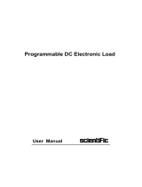
Model 2720A Accessories
1000009 – Single Unit Rack Mount Kit
Fits most standard 19” racks. Mounting
hardware included.
1000010 – Dual Unit Rack Mount Kit
Fits most standard 19” racks. Mounting
hardware included.
CBL-3102 – BNC Cable
3-ft BNC cable used for general purpose I/O
connections.
BNC-3285 – BNC (F-M-F)
BNC Tee Connector
Used for splitting 50Ω, BNC-type connections
used for trigger, main output, modulation,
and sync I/O’s.
1583-3 – 3ft Heavy Duty GPIB Cable
1583-6 – 6ft Heavy Duty GPIB Cable
1583-9 – 9ft Heavy Duty GPIB Cable
2720A-901-01– 2720A User’s Manual
Printed Version
1000030-840-01
• 2720A User’s Manual
• WaveWorks DDS Wave Creation
Software
• LabVIEW Drivers
(Included Accessories)
740565-6 - 6 ft RS-232C Cable
DB9 to DB9 F/F RS-232C, null modem cable
for 2700 series hybrid function arbitrary
waveform generators.
(Included Accessory)
161006600 – Power Cord for 120 VAC
Operation
Contact TEGAM for alternate voltages.
(Included Accessory)
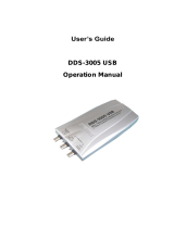
1000001 – USB to RS232 Converter
Allows serial communications between the
RS232 interface of the 2720A and the USB
port of a pc. Kit includes software driver for
Windows 98SE/ME/2000/XP, Mac 8.6/9/10,
and Linux 2.4 & higher.

Model 2720A - 31 MHz Function/Arbitrary Waveform Generator Instrument Description
1-5
Performance Specifications:
Frequency Characteristics (Standard Waveforms)
Sine - 10 μHz to 31 MHz
Square - 10 μHz to 31 MHz
Pulse - 500 μHz to 10 MHz
Triangle, Ramp - 10 μHz to 500 KHz
Frequency Accuracy - 0.002% (20 ppm)
Frequency Resolution - 10 digits or 10 μHz
Arbitrary Characteristics
Waveform length - 2 points to 500,000 points
Vertical resolution - 12 bits
Sampling rate - 20 ns to 50 s
Sampling Accuracy - 0.002% (20 ppm)
Sampling Resolution - 4 digits or 10 ps
Output Characteristics
Amplitude Range - 10 mV to 10 Vp-p into 50 Ω
Resolution - 3 digits (1000 counts)
Amplitude Accuracy - ± 1% ± 20 mV of the programmed output from 1 V-10 V
Flatness - 0.2 dB to 1 MHz
- 0.5 dB to 20 MHz
Offset Range - ± 4.5 V into 50 Ω, depending on the Amplitude
Setting
- The offset voltage has three ranges as follows:
Output Voltage Range Constraints of Amplitude + Offset
1.00 volt to 10.00 volts (Vp-p)/2 + |offset| <= 5 volts
0.100 volt to 0.999 volt (Vp-p)/2 + |offset| <= 0.5 volts
0.010 volt to 0.099 volt (Vp-p)/2 + |offset| <= 0.05 volts
Offset Resolution - 10 mV with 3 digits resolution
(1 mV resolution for Vout < 1V)
Offset Accuracy - ± 1% ± 10 mV into 50 Ω
Output Impedance - 50 Ω
Output Protection - The instrument output is protected against short circuit or
42 V maximum input voltage.
Filters - 9 pole Elliptic and 5 pole Bessel filters

Model 2720A - 31 MHz Function/Arbitrary Waveform Generator Instrument Description
1-6
Model 2720A - Specifications cont’d:
Waveform Characteristics
Harmonic Distortion - DC-100 kHz -60dBc
- 100 kHz-1 MHz -45dBc
- 1 MHz-15 MHz -35dBc
- 15 MHz-30 MHz -25dBc
Spurious - DC-1 MHz < -65dBc
Square Rise/Fall Time - < 12 ns (10% to 90%) at full amplitude into 50 Ω
Variable Duty Cycle - 20% to 80% to 5 MHz, 40% to 60% up to 20 MHz
Symmetry at 50% - < 1%
Aberrations - < 2% of p-p amplitude ± 50 mV.
Operating Modes
Continuous - Output continuous at programmed parameters.
Triggered - Output quiescent until triggered by an internal or external
trigger, then one waveform cycle is generated to
programmed parameters. Up to 10 MHz trig rate for ARB
waveforms and 5 MHz in DDS mode.
Gate - Same as triggered mode, except waveform is executed for
the duration of the gate signal. The last cycle started is
completed.
Burst - 1- 99,999 cycles
Phase - -360° to +360°, 0.1° resolution
Trigger Source - Trigger source may be internal, external or manual.
Internal trigger rate 0.01 Hz-1 MHz
Modulation Characteristics
Amplitude Modulation
- Internal: - 0.01 Hz-20 kHz sine wave, square or triangle
Variable modulation from 0% to 100%.
- External: - 5 Vp-p for 100% modulation, 10 kohms input
impedance.
Frequency Modulation
- Internal: - 0.01 Hz-20 kHz sine wave, square or triangle
- External: - 5 Vp-p for 100% deviation, 10 kohms input
impedance.
FSK
- Internal rate - 0.01 Hz-1 MHz
- External - 1 MHz max

Model 2720A - 31 MHz Function/Arbitrary Waveform Generator Instrument Description
1-7
Model 2720A - Specifications cont’d:
Sweep Characteristics
Sweep Shape: - Linear and Logarithmic, up or down
Sweep Time: - 20 ms to 500 s.
Sweep trigger - internal, external, continuous or burst
Variable Phase
Range - +360° to -360°
Resolution - 0.1°
Inputs and Outputs
Trigger In - TTL compatible.
- Maximum rate 10 MHz.
- Minimum width 50 ns.
- Input impedance 1 kΩ nominal.
Sync Out - TTL pulse at programmed frequency, 50 Ω
source impedance. (fan out =15)
Modulation IN - 5 Vp-p for 100% modulation.
- 10 kΩ input impedance.
- DC to 20 kHz minimum bandwidth.
Reference IN - 10 MHz, TTL compatible
Reference OUT - 10 MHz, TTL compatible (fan out =15)
Computer Interfaces:
GPIB - IEEE 488.2 SCPI compatible
RS-232C - 1200, 2400, 4800, 9600, 19200, 38400, 57600 or 115000
Baud, 8 data bits, 1 stop bit, no parity

Model 2720A - 31 MHz Function/Arbitrary Waveform Generator Instrument Description
1-8
Model 2720A - Specifications cont’d:
General Specifications
Settings Storage - 50 (49 programmable) full panel settings (non-volatile)
Arbitrary memory - 500 kB in flash memory (non-volatile)
Dimensions - Width = 8.4 in. (213 mm)
- Height = 3.5 in. (88 mm)
- Depth = 108 in. (275 mm)
Weight - 6.6 lbs. (3 Kg.)
Power - < 40 VA max.
Supply Voltage - 110 V/220 V (100 V to 240 VAC, ±10%)
Line Frequency - 50/60 Hz (47 Hz to 63 Hz)
Operating Temperature - 32°F to 122°F (0°C to +50°C)
Storage Temperature - -22°F to 160°F (-30°C to +71°C)
Humidity - 90% RH, 32°F to 86°F (0°C to 30°C)
EMC - According to EN55011 class B for radiated and
conducted emissions.
ESD Immunity - According to EN55082
Safety Specifications - According to EN61010
CE certified
NOTE: Specifications are verified according to the performance check procedures in the technical
manual. Specifications not verified in the manual are either explanatory notes or general
performance characteristics only.

Preparation for Use
INSTRUMENT DESCRIPTION
PREPARATION FOR USE
QUICK START INSTRUCTIONS
OPERATING INSTRUCTIONS
PROGRAMMING & INTERFACING
SERVICE INFORMATION
Model 2720A - 31 MHz Function/Arbitrary Waveform Generator Instruction Manual 2-1

2-2

2-3
Model 2720A - 31 MHz Function/Arbitrary Waveform Generator Preparation for Use
Unpacking & Inspection:
Each 2720A is put through a series of electrical and mechanical inspections before shipment to the
customer. Upon receipt of your instrument unpack all of the items from the shipping carton and
inspect for any damage that may have occurred during transit. Report any damaged items to the
shipping agent. Retain and use the original packing material for reshipment if necessary.
Upon receipt, inspect the carton for the following items:
(1) Model 2720A - 31 MHz Function/Arbitrary Waveform Generator
(1) CD: Model 2720A User’s Manual, WaveWorks DDS – Wave Creation Software, LabVIEW Drivers
(1) RS-232C Cable
(1) Power Cord
Safety Information & Precautions:
The following safety information applies to both operation and service personnel. Safety
precautions and warnings may be found throughout this instruction manual and the equipment.
These warnings may be in the form of a symbol or a written statement. Below is a summary of
these precautions. TEGAM assumes no liability for a customer’s failure to comply with these
requirements. Model 2720A is a Safety Class I instrument.
Terms in This Manual:
CAUTION statements identify conditions or practices that could result in damage to the equipment
or other property.
WARNING statements apply conditions or practices that could result in personal injury or loss of
life.
Terms as Marked on Equipment:
CAUTION indicates a personal injury hazard not immediately accessible as one reads the marking,
or a hazard to property including the equipment itself.
DANGER indicates a personal injury hazard immediately accessible as one reads the marking.
!

2-4
!
Model 2720A - 31 MHz Function/Arbitrary Waveform Generator Preparation for Use
Safety Information & Precautions Cont’d:
Symbols:
As Marked in This Manual:
!
This symbol denotes where precautionary information may be found.
As Marked on Equipment:
!
Caution – Risk of Danger
Danger – Risk of Electric Shock
Earth Ground Terminal-
l
On
O
Off
Chassis Terminal
Alternating Current
Earth Ground Terminal / Guard
Grounding the Equipment
This product is grounded through the grounding conductor of the power cord.
WARNING: To avoid electrical shock or other potential safety hazards, plug the power cord into
a properly wired receptacle before using this instrument. The proper grounding of this instrument
is essential for safety and optimizing instrument operation. The power cord must meet IEC safety
standards.
Danger Arising from Loss of Ground
WARNING: If the connection to ground is lost or compromised, a floating potential could develop
in the instrument. Under these conditions all accessible parts, including insulating parts such as
keypads and buttons could develop a hazardous voltage and put the user at risk.

2-5
!
Model 2720A - 31 MHz Function/Arbitrary Waveform Generator Preparation for Use
!
Use the Proper Fuse
To avoid fire hazard, use only the correct fuse type as specified for the AC power supply in the
“Preparation for Use”” or “Service” sections of this manual. Note that the fuse rating for 100 &
120-volt operation is different than the rating for 200 & 240-volt operation. Information about the
proper fuse type is also printed on the rear panel of the instrument.
Refer fuse replacement to qualified service personnel.
Do Not Use in Explosive Environments
WARNING: The 2720A is not designed for operation in explosive environments.
Do not Operate Without Covers
WARNING: This device should be operated with all panels and covers in place. Operation with
missing panels or covers could result in personal injury.
FOR QUALIFIED SERVICE PERSONNEL ONLY
Servicing Safety Summary:
Do Not Service Alone
Do not perform service or adjustment on this product unless another person capable of rendering
first aid is present.
Use Care When Servicing with Power On or Off
Dangerous voltages may exist at several points in this product. To avoid personal injury or
damage to this equipment, avoid touching exposed connections or components while the power is
on. Assure that the power is off by unplugging the instrument when removing panels, soldering, or
replacing components.
WARNING: The instrument power source is electronically controlled meaning that there is
power present throughout the instrument even when the instrument is in the OFF state.
Always unplug the instrument and wait 5 minutes before accessing internal components.
Power Source
This product is intended to connect to a power source that will not apply more than 256V RMS
between the supply conductors or between either supply conductor and ground. A protective
ground connection by way of the grounding conductor in the power cord is essential for safe
operation.

2-6
!
Model 2720A - 31 MHz Function/Arbitrary Waveform Generator Preparation for Use
Line Voltage & Fuse Selection:
CAUTION: DO NOT APPLY POWER TO THE INSTRUMENT BEFORE READING THIS SECTION:
Model 2720A is powered by a universal power supply. The 2720A design allows it to operate from
90 V to 264 V @ 47 Hz to 63 Hz. It is recommended that the fuse size be matched to the supply
voltage before powering the unit.
First, determine the supply voltage that the instrument will be operating under and verify that the
supply voltage does not fall outside of the allowable operating range (90 to 264 VAC). Then select
the appropriate fuse size using the table below:
FUSE SIZE
110/120
VAC 5 X 20 mm
1 A Slow Blow
250 V
220/240
VAC 5 X 20 mm 0.5A
250 V
Make sure that the proper fuse size is installed. Use a slow blow fuse UL/CSA approved for 110 V
operation and an IEC127 fuse for 220 V. The proper fuse types and ratings can be found on the
rear panel.
The instrument is ready for power up. Proceed to “Operating Instructions” to continue with setup &
operation.
/