Page is loading ...

muldoor-installaon-Print.pdf
1
Large enclosure installation
Due to shipping restrictions larger enclosures need
to be assembled once arriving. This is a fairly straight
forward process, wipe away application area, put
gasket around the edge of one of the enclosures and
then, using the included bolt pack, bolt together the
two sides to form a water tight seal.
Gasket layout
Gasket should reach from edge
to edge of enclosure.
Start at bottom
corner of enclosure
Tightly butt gasket against
gasket to keep seal.
Start with alignment holes*
(marked in red) to ensure
proper interlock alignment
.38-16x1 in. flange bolts
used for bolting sections
together. (110 -130 torque)
*Two alignment holes are located on the front side
of the enclosure. These are slightly smaller and will
ensure proper alignment during assembly.
3/16” x 1/2” strip gasket
around perimeter
Keep gasket outside hole locations!
!
!

muldoor-installaon-Print.pdf
2
Interlock installation
Hex Rod Hex Rod
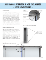
Figure D:
HEX ROD INSTALLATION
Figure E:
LATCHING DETAIL
A
INTERLOCK INSTALLATION INSTRUCTIONS
Step 1: Start by ensuring a level working area for
installation and alignment. In order for this interlock
system to work properly, proper alignment of
modular connection holes are essential. As explained
on the previous page, start with alignment holes for
proper alignment.
Step 2: Once all of the enclosures are in place and
properly aligned, loosen all of the set screws on the
hex rod adapters for all of the enclosures within this
interlock system. Shown in Figure A, adapters are
located in red.
Step 3: Slide the hex rod (shown in blue in Figure
D) horizontally inside the next enclosure, the hex
rod will then protrude approximately halfway
into the other hex rod adapter of the adjacent
enclosure. The new hex rod will now link up to the
corresponding rod just installed.
Step 4: Re-tighten all of the set screws on the
rod adapters.
Detail A:
ROD DETAIL Rod Guide
Hex Rod
Adapter
(in red)
Hex Rod
(in blue)
Set Screws
for Hex Rod
Adapter
TROUBLESHOOT
• If all doors are not engaging properly at the lock points,
adjustments can be made at the vertical rods. To do so,
loosen the set screws on the vertical rod adapters; located
above the interlock assemblies (shown in red). See Figure E.
There, you can adjust the position and grab of the interlock.
Re-tighten into place after tinkering. If problems still persist,
adjust the vertical rod adapters near the horizontal ones at
the enclosure’s ceiling (view Figure A).
Apply the same concept to these, and then re-tighten.
• For best results make sure that all intersecting points of
the hex rod and the rod guide are lubricated.
• If more help is needed please visit saginawcontrol.com
for in depth installation instructions and videos or contact
Saginaw Control.
Set Screws
(in red)
Watch an interlock adjustment video
Found at SaginawControl.com
/

