Page is loading ...

GLD Pro Gas Leak Detector
User Manual
Version 4
BR21603 October 2020


Contents
1.0 Introduction 4
2.0 Battery charging 5
3.0 Powering up 6
4.0 Zeroing the unit 6
5.0 Prior to operation 6
6.0 Detecting leaks 7
7.0 Specifications 7
8.0 Maintenance 8
9.0 Troubleshooting 8
10.0 Technology 9
11.0 Interpretation of results 10
12.0 Back label explanation 11
13.0 Case specifications 12
14.0 Service 12

Operating instructions
1.0 Introduction
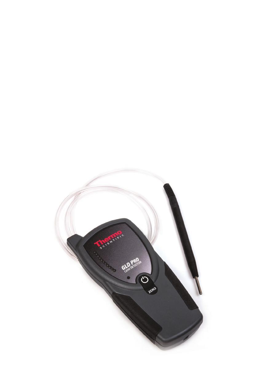
The Thermo Scientific™ leak detector is specifically designed for use with gas
chromatography (GC) systems. It detects minute leaks of any gas with a thermal
conductivity different from air. The reference gas inlet (Figure 1) draws in ambient air for
comparison to air drawn into the sample probe. A leak is indicated by both an LED light
display and an audible alarm.
If this instrument is used in any manner other than described in the manual, the CE
declaration is void.
Leak Detector LED Indicator Display and Interpretation
Unit State -
Powered
On/O
LED Color LED State Interpretation
Unit Battery
State
On Blue >
Red & Yellow
On/Blue flashes
once, red and yellow
cycle for 15 seconds/
O
Unit is powering on and running
startup sequence
On Blue On/Steady Ready for use, battery does not
require charging
On Blue On/Constant
Flashing
IMPORTANT: Unit must be
charged
Power Button
Depressed
NONE NONE Battery has fully discharged,
charge immediately
Unit Charging
State
On/O Green On/Flashing Unit is plugged in to the AC adaptor
or USB cable and is charging a very
low battery (trickle charging)
On/O Green On/Steady Unit is plugged in to AC adaptor
or USB cable and is in full charge
mode
On/O Green O Unit is plugged into AC adaptor
or USB cable and the unit is fully
charged
Unit Operation
On Red or Yellow On/Steady Unit is indicating a dierence in
thermal conductivity between probe
and reference
On Red & Yellow On/Cycling for
4 seconds/O
Zero set button has been depressed
and unit is rezeroing
4

2.0 Battery charging
The leak detector should be fully charged prior to use. Only use the AC adaptor
provided. To charge the battery, first install the correct plug for your country’s AC outlets
onto the provided AC adaptor. Insert the AC adaptor into an electrical outlet, and then
insert the barrel plug on the other end of the AC adaptor into the connector on the
bottom of the leak detector unit. The green battery charge indicator LED will illuminate.
When the battery is fully charged, the green battery charge indicator LED will go out.
When the leak detector’s charge is low, the BLUE LED located between the red and
yellow LEDs will begin to flash.
If unit is off, the BLUE LED may flash when the power button is depressed. If the battery
is fully discharged, no LED will illuminate.
NOTE: If the battery is fully discharged, no LED will illuminate.
CAUTION: For the health of the battery, it is not recommended to continuously operate
the leak detector when it is plugged in and charging. However, if your battery has been
allowed to fully discharge and will no longer hold a charge, the unit can be operated while
plugged in receiving charge directly from the power supply. To operate the leak detector
while it is plugged in, follow the instructions for regular operation, and when the blue LED
illuminates steady or flashing the unit is ready to use.
CAUTION: The leak detector contains a nickel-metal hydride (NiMH) battery. Like other
battery-operated devices, if the battery is left for long periods of time without being
charged, it can discharge to a point where the battery cannot accept a charge. We
recommend that you charge the battery at least once every 3 months. If your leak
detector is used often for routine maintenance, as recommended, more frequent
charging may be necessary.
CAUTION: Replacement of the rechargeable battery in this unit is performed at the
factory. There are no serviceable parts inside this unit. Opening the case or tampering
with the internal parts will void the factory warranty.
NOTE: Recharging a low battery can take approximately 6 hours.
NOTE: The leak detector may get warm to the touch during charging, but this is normal
and not a safety concern.
5

3.0 Powering up
Depress and hold the power button (Figure 1) until the unit responds with the wake-up
mode. The leak detector will run through a self calibration sequence for approximately
15 seconds. During this time DO NOT attempt to zero the unit.
4.0 Zeroing the unit
After the LED lights stop flashing, the unit is ready for use. The instrument may need
to be zeroed periodically between uses, especially if it is moved from room to room or
between areas of differing temperature or humidity. Do not attempt to zero the unit while
the probe is stored in the holder. The probe MUST be removed from the probe docking
station before zeroing the unit. To re-zero, press the zero set button. The unit will run a
self-calibration sequence for approximately 4 seconds. When all LED lights stop flashing
and the blue LED light is lit, the unit is ready for use.
NOTE: To avoid false readings, do not attempt to use or zero the unit while the self-
calibration sequence is in progress.
5.0 Prior to operation
Verify the operation of the leak detector before each use by sampling gas from a GC split
vent or other source of hydrogen or helium. Also, visually inspect the probe tip, reference
gas inlet, and exhaust port for obstructions (Figure 1).
IMPORTANT: Fittings being checked must be clean and dry; liquid leak detecting
agents, dust, and other debris may damage the leak detector if drawn into the probe.
The leak detector responds to almost any gas you can smell and many gases that you
can’t smell. Solvent vapors, split vent exhaust, or even strong air currents around the
probe or reference inlet can cause instability or false positive readings. Be careful not to
breathe into the reference inlet when checking for leaks or to cover/block the inlet with
your hand.
6
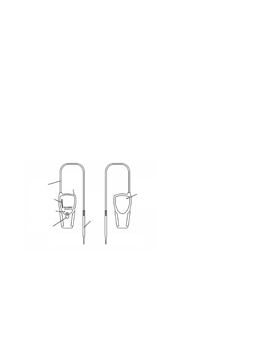
Figure 1 – Leak detector schematic

6.0 Detecting leaks
Slowly move the probe tip around fittings and other potential leak sources. If the leak
detector senses a gas other than air, the LED bar graph will begin to light, with more
lights indicating a more significant leak. On the 3rd red or 2nd yellow LED, an audible
tone will begin to beep. The more LEDs that illuminate, the faster the beep. When the
last red or yellow LED illuminates, the beep becomes a steady tone. The red LED lights
indicate a helium or hydrogen leak. The yellow LED lights indicate a nitrogen, argon, or
carbon dioxide leak. Remove the probe from the vicinity of the leak and allow the unit to
return to zero. If a large amount of gas has entered the probe, it may take a few seconds
for the instrument to clear itself. Do not attempt to zero the unit while it is clearing out
the gas from the probe. This may cause the unit to malfunction. Place the probe near
the leak again to confirm its location. The reference gas inlet (Figure 1) must not be
restricted or the unit will not operate correctly. Similarly, the exhaust port allows the gas
being tested to exit the leak detector and must remain unobstructed. The exhaust port is
located in the probe docking station.
CAUTION: This unit is designed to detect TRACE AMOUNTS of hydrogen arising
from a small leak in a nonflammable environment, e.g., laboratory
room air, etc. This unit is rated for use in a nonflammable atmosphere
where the sample gas may become sufficiently high in concentration to
become explosive.
NOTE: To disable the audible beep during leak detection, depress and hold
the zero set button for 2–3 seconds. After you hear a steady tone for 1
second, release the button; the beep function is disabled. To turn the
beep function on again, depress and hold the zero set button. The beep
function is always enabled at power up.
NOTE: The leak detector will power down after 6 minutes of operation. This
feature prevents excess battery discharge if the unit is accidentally left on.
7.0 Specifications
Power Rating: 5 volts DC, 1 A (AC adaptor & USB charging cable supplied)
Battery Rating: 12 hours normal operation
Operating Temp. Range: 50-98.6 °F (10-37 °C)
Humidity Range: 0–97%
Warranty: 1-year limited warranty
Certifications: CE (EU, Korea, Japan, Australia) CSA/UL tested, not listed
Compliance: WEEE, RoHS, China RoHS2
Altitude: Up to 2000m above mean sea level
Pollution degree: 2
Indoors Use Only
7
8.0 Maintenance
Avoid spilling liquids onto the unit, or it may malfunction. If a liquid is spilled onto the unit,
turn off the power immediately, remove heavy liquids with a dry towel, and let the unit
sit until the liquid dries. Dust and debris can enter the probe tip of the leak detector and,
over time, can clog the smallbore tubing inside the unit. To prevent this, clean the probe
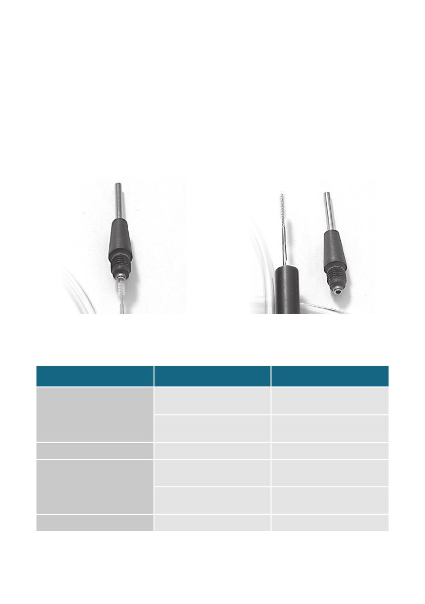
tip periodically. To clean the probe tip, unscrew the cap to expose the brush (Figures 2
and 3). Gently clean the probe using a small brush or your fingers to remove dust and
debris, then replace the cap. Do not use liquids to clean the probe. Liquids can damage
the leak detector if drawn in through the probe.
Information on where to have the unit sent for maintenance or service* is listed at the end
of this document.
9.0 Troubleshooting
8
Problem Possible Cause Suggested Solution
Sensitivity decreased
Probe clogged Clean the probe tip to remove
any debris
Probe line punctured Visually inspect probe line for
holes*
Response decreased Detector not zeroed Re-zero detector
LED bar graph stays lit
during operation
Detector re-zeroed before unit
was purged out
Allow adequate time for
detector to purge, then re-zero
Reference gas inlet covered by
hand or other object
Remove obstruction
Does not power up Batteries need to be charged Charge unit
Figure 2 – Cap unscrewed and partially
removed
Figure 3 – Cap removed, exposing probe tip
brush for cleaning.
*Contact Thermo Fisher Scientific or your local representative for return instructions for servicing a damaged
unit. Additional charges may apply if the warranty has expired or the unit is damaged due to misuse.
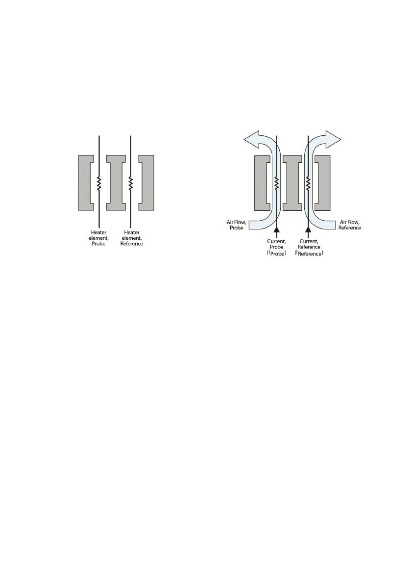
LEFT: Dual analysis is achieved with
heater elements positioned in separate
flow chambers.
RIGHT: Probe and reference air streams
are simultaneously monitored for thermal
conductivity. Differences in air composition
are indicated by differences in the heater
element currents.
10.0 Technology
The leak detector measurement is based on thermal conductivity comparisons between
the probe air and a reference air. The device employs a dual thermistor technology that
measures the ratio of [probe]:[reference] heat exchange values and displays the results on
an LED scale (Figure 4). Under ideal operating conditions, a ratio of 1:1 indicates identical
air samples for both [probe] and [reference], and therefore, no leak is present.
Because of slight differences in air temperature and/or humidity between the reference
inlet (Figure 1) and the probe tip, a small response indicated by a single red or yellow LED
light is generally insufficient to positively identify a gas leak. Small to moderate leaks are
reliably indicated with 3 red or 2 yellow LED lights and an intermittent beep. Larger leaks
are indicated with all red or yellow LED lights lit and a continuous audible alarm.
9

11.0 Interpretation of results
Figure 5 illustrates the leak detector’s LED light response range. The greater the number
of red or yellow LED lights lit correlates in general to the size of the leak. NOTE: The
leak detector is not a quantitative device, rather it is designed to detect leaks in gas line
connections commonly associated with laboratory equipment.
**CAUTION: This unit is designed to detect TRACE AMOUNTS of hydrogen and rising from a small
leak in a non flammable environment, e.g., laboratory room air, etc. This unit is rated for use in a
non flammable atmosphere where the sample gas may become sufficiently high in concentration to
become explosive.
Tip drift
Tip drift is the phenomenon when a false LED light response is registered as the unit
is quickly turned or swept in dramatic arc movements. Tip drift is inherent to all dual
thermistor leak detector technology and is based in large part on the asymmetry of the
flow cells; shaking or tipping the unit influences the air flow profiles, which impacts the
rates of heat exchange. If the device is functioning normally, the LED light signal will return
to zero in 3–5 seconds after the unit is held still. In extreme cases, the unit may require
another “zero” cycle before using. To avoid tip drift, be sure to hold the unit steady while
making measurements.
Gas Minimum Detectable
Leak Rate (atm cc / sec)
Indicating
LED Light Color
Helium 1.0 × 10⁻⁵ Red
Hydrogen** 1.0 × 10⁻⁵ Red
Nitrogen 1.4 × 10⁻³ Yellow
Argon 1.0 × 10⁻⁴ Yellow
Carbon dioxide 1.0 × 10⁻⁴ Yellow
Figure 5 – LED light response chart for the leak detector. A 1:1 ratio of I Probe : I Reference
indicates no leak present. Red LED lights indicate the presence of helium and/or hydrogen.
Yellow LED lights indicate the presence of nitrogen, argon, and/or carbon dioxide
10
Blue LED and all 3 yellow LEDs
and audible continuous alarm:
significant leak detected
Blue LED and 4 red LEDs:
small leak detected
Blue LED only:
no leak detected
Blue LED and all 7 red LEDs
and audible continuous alarm:
significant leak detected
11
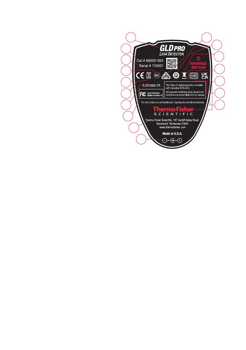
12.0 Back label explanation
1. Product name.
2. Product catalog number.
3. Product serial number.
4. Passed California Energy Commission
(CEC) Battery Charging System (BCS) testing.
5. CE mark: see Declaration of Conformity
6. KC mark - Korea Certification
7. Electrical parameters.
8. This device complies with part 15 of the FCC
Rules. Operation is subject to the following
two conditions:
1) This device may not cause harmful interference.
2) This device must accept any interference received,
including interference that may cause
undesired operation.
9. Manufacturer company name, address, and contact information.
10. AC adaptor polarity
11. RCM (Regulatory Compliance Mark) - Australia certification
12. China RoHS 2
13. Unit is WEEE compliant.
14. This Class A digital apparatus complies with Canadian ICES-003.
15. Units must be sent back to Thermo Fisher Scientific for service.
16. Unit is VCCI compliant
17. Unit is UKCA compliant
For the most up-to-date information, see our website www.thermofisher.com
1
2
3
5
8
4
6
7
9
10
11
12
13
15
14
16
17

13.0 Case specifications
14.0 Service
The Thermo Scientific leak detector carries a 1-year limited warranty from time of
purchase. Please have the leak detector serial number available when calling Thermo
Fisher Scientific with any concerns you may have. Additional charges may apply if the
warranty is expired or the damage is due to misuse.
Expected battery lifetime is 2 years from time of purchase. Customers will need to return
the unit to Thermo Fisher Scientific for battery replacement. At that time, preventative
maintenance services can also be performed on the unit. A fee will be charged for
servicing the unit.
12

13

Inhaltsverzeichnis
1.0 Einführung 16
2.0 Akku-Aufladung 17
3.0 Einschalten 18
4.0 Nullabgleich des Geräts 18
5.0 Vor der Inbetriebnahme 18
6.0 Erkennung von Lecks 19
7.0 Technische Daten 20
8.0 Wartung 20
9.0 Fehlersuche 21
10.0 Technologie 22
11.0 Interpretation der Ergebnisse 22
12.0 Erklärung des Labels auf der Rückseite 24
13.0 Spezifikationen des Gehäuses 25
14.0 Service 25

Betriebsanleitung
1.0 Einführung
Der Lecksucher von Thermo Scientific wurde speziell zur Verwendung mit
gaschromatographischen (GC) Systemen entwickelt. Er detektiert kleine Lecks von
Gasen, die eine andere Wärmeleitfähigkeit als Luft aufweisen. Der Referenzgas-Einlass
(Abbildung 1) saugt Umgebungsluft an, die dann mit dem Gas in der Probensonde
verglichen wird. Das Ausmaß der Leckage wird durch eine LED-Leuchtanzeige und durch
einen akustischen Alarm angezeigt.
Die CE-Erklärung ist hinfällig, wenn das Gerät auf eine andere Weise als in der
Bedienungsanleitung beschrieben verwendet wird.
LED-Anzeige des Lecksuchers und ihre Interpretation
Betriebszustand
des Geräts –
Ein/Aus
LED-Farbe LED Zustand Interpretation
Akkuladezustand
des Geräts
Ein Blau >
Rot und Gelb
Ein/Blau blinkt einmal,
rot und gelb blinken
abwechselnd für 15
Sekunden/Aus
Gerät schaltet sich ein und durchläuft
die Startsequenz
Ein Blau Ein/Konstant Betriebsbereit, Akku-Aufladung nicht
erforderlich
Ein Blau Ein/Konstantes
Blinken
WICHTIG: Gerät muss aufgeladen
werden
Betriebsschalter
gedrückt
KEINE KEINE Akku ist vollständig entladen.
Sofort aufladen!
Ladezustand
des Geräts
Ein/Aus Grün Ein/Blinkt Gerät ist mit dem AC-Adapter oder
mit einem USB-Kabel verbunden und
lädt einen stark entladenen Akku auf
(Erhaltungsladung)
Ein/Aus Grün Ein/Konstant Gerät ist mit dem AC-Adapter oder
mit einem USB-Kabel verbunden und
befindet sich im Modus Vollladung
Ein/Aus Grün Aus Gerät ist mit dem AC-Adapter oder
mit einem USB-Kabel verbunden und
ist voll aufgeladen
Betrieb
des Geräts
Ein Rot oder Gelb Ein/Konstant Gerät zeigt Dierenz der
Wärmeleitfähigkeit zwischen Sonde
und Referenz an
Ein Rot und Gelb Ein/4 Sekunden
langes Hin- und
Herschalten/Aus
Nullungstaste wurde gedrückt und
Gerät führt neuen Nullabgleich durch
16

2.0 Akku-Aufladung
Der Lecksucher sollte vor der Verwendung voll aufgeladen sein. Verwenden Sie
dazu bitte nur den AC-Adapter oder das USB-Kabel, die beide mit dem Gerät geliefert
werden. Um den Akku mithilfe des AC-Adapters aufzuladen, befestigen Sie bitte
zunächst den passenden Stecker für die Netzsteckdosen Ihres Landes am mitgelieferten
AC-Adapter. Stöpseln Sie den AC-Adapter in eine Netzsteckdose und stecken Sie
dann den Klinkenstecker am anderen Ende des AC-Adapters in die Anschlussbuchse
am unteren Ende des Lecksuchers. Um den Akku mithilfe des USB-Kabels aufzuladen,
schließen Sie das USB-Kabel einfach an das Gerät und an einen USB-Port an. Während
des Aufladens leuchtet die grüne LED, die anzeigt, dass der Akku geladen wird. Wenn
der Akku voll aufgeladen ist, erlischt diese LED. Wenn der Akku des Lecksuchers stark
entladen ist, fängt die blaue LED zwischen den roten und gelben LEDs an zu blinken.
Es ist wichtig, dass der Lecksucher bei Blinken der blauen LED aufgeladen wird, um die
vollständige Entladung und potenzielle Schäden des Akkus zu vermeiden.
HINWEIS: Wenn der Akku vollständig entladen ist, leuchtet keine LED.
VORSICHT: Um den Akku in optimalem Zustand zu halten, sollte der Lecksucher
während des Aufladens nicht kontinuierlich betrieben werden. Wenn Ihr Akku sich jedoch
vollständig entladen hat und keine Ladung mehr hält, kann das Gerät betrieben werden,
wenn es direkt über das Netzteil versorgt wird. Um den Lecksucher mit Netzanschluss
zu betreiben, befolgen Sie bitte die Anweisungen für den normalen Betrieb; wenn die
blaue LED konstant leuchtet oder blinkt, ist das Gerät betriebsbereit.
VORSICHT: Der Lecksucher enthält einen Nickel-Metallhydrid (NiMH)-Akku. Wie bei
anderen akkubetriebenen Geräten darf der Akku nicht über längere Zeiträume ohne
Aufladung verbleiben. Wir empfehlen, den Akku mindestens einmal alle 3 Monate
aufzuladen. Wenn Ihr Lecksucher wie empfohlen oft zur routinemäßigen Wartung
verwendet wird, kann häufigeres Aufladen erforderlich sein.
VORSICHT: Der Austausch des aufladbaren Akkus in diesem Gerät wird werkseitig
durchgeführt. Dieses Gerät enthält keine vom Anwender zu wartenden Teile. Bei Öffnen
des Gehäuses oder Manipulieren der Innenteile erlischt die werkseitige Garantie.
HINWEIS: Das Aufladen eines schwachen Akkus kann etwa 6 Stunden dauern.
HINWEIS: Der Lecksucher kann beim Aufladen handwarm werden; das ist jedoch normal
und kein Anlass zu Sicherheitsbedenken.
17
3.0 Einschalten
Drücken Sie den Betriebsschalter (Abbildung 1) und halten Sie ihn solange gedrückt, bis
das Gerät eine etwa 15 Sekunden dauernde Startsequenz einleitet; während dieser Zeit
blinken die roten und gelben LEDs. Während der Startsequenz darf das Gerät NICHT
genullt werden.
4.0 Nullabgleich des Geräts
Wenn die LEDs nicht länger blinken, ist das Gerät betriebsbereit oder kann genullt
werden. Zwischen Einsätzen muss das Gerät unter Umständen regelmäßig genullt
werden, besonders wenn es in unterschiedlichen Räumen oder in Bereichen
unterschiedlicher Temperatur oder Luftfeuchtigkeit verwendet wird. Bitte nicht versuchen,
das Gerät zu nullen, während sich die Sonde in der Halterung befindet. Vor der Nullung
MUSS die Sonde aus der Sondenhalterung herausgenommen werden. Zur erneuten
Nullung die Nullungstaste drücken. Das Gerät durchläuft eine etwa 4 Sekunden lange
Sequenz zur erneuten Nullung. Wenn alle LEDs aufhören zu blinken und die blaue LED
leuchtet, ist das Gerät betriebsbereit.
HINWEIS: Um falsche Messwerte zu vermeiden, dürfen Sie nicht versuchen, das Gerät
zu benutzen oder zu nullen, während die Nullungssequenz läuft.
5.0 Vor Inbetriebnahme
Überprüfen Sie den Betrieb des Lecksuchers vor jedem Gebrauch, indem Sie Gas aus
einem GC-Splitausgang oder aus einer Wasserstoff- oder Helium-Quelle entnehmen.
Prüfen Sie außerdem die Sondenspitze, den Referenzgas-Einlass und die Auslassöffnung
auf Blockierungen (Abbildung 1).
WICHTIG: Zu prüfende Fittings müssen sauber und trocken sein; Flüssigkeiten, Staub
und andere Verunreinigungen können den Lecksucher beschädigen, wenn sie in die
Sonde gezogen werden.
18
Abbildung 1 – Schematische Darstellung des Lecksuchers
VORDERANSICHT RÜCKANSICHT
Referenzgas-
Einlass
(Frei halten)
Spitze der
Probensonde
Sondenhalterung/
Auslassöffnung
Probensonde
LED-Leuchten
zur Leckanzeige
LED-Akkuladeanzeige
Betriebsschalter/
Nullungstaste

Der Lecksucher spricht auf praktisch jedes Gas an. Lösemitteldämpfe, Abgas aus
Splitausgängen und sogar starke Luftströme um die Sonde oder den Referenzgas-Einlass
können Instabilität verursachen oder falsche positive Messwerte liefern. Achten Sie
darauf, dass bei der Prüfung auf Lecks keine Atemluft in den Referenzeinlass gelangt und
blockieren oder decken Sie ihn nicht mit der Hand ab.
6.0 Erkennung von Lecks
Führen Sie die Sondenspitze des eingeschalteten und genullten Lecksuchers langsam um
Fittings herum und an anderen potenziellen Leckquellen vorbei. Wenn der Lecksucher ein
anderes Gas als Luft wahrnimmt, fangen die LEDs an zu leuchten, wobei mehr LEDs ein
größeres Leck anzeigen. Bei der dritten roten bzw. zweiten gelben LED wird außerdem
ein akustisches Signal ausgelöst. Je mehr LEDs leuchten, um so schneller wiederholt
sich der Piepton. Wenn die letzte rote oder gelbe LED leuchtet, geht der Piepton in einen
Dauerton über. Die roten LEDs zeigen ein Helium- oder Wasserstoffleck an. Die gelben
LEDs zeigen ein Leck von Stickstoff, Argon oder Kohlendioxid an. Entfernen Sie die
Sonde aus der Nähe des Lecks und lassen Sie das Gerät auf Null zurückgehen. Wenn
eine große Gasmenge in die Sonde eingetreten ist, kann es ein paar Sekunden dauern,
bevor das Gerät das Gas eliminiert und sich selbst zurückgesetzt hat. Bitte versuchen
Sie nicht, das Gerät zu nullen, während es das Gas aus der Sonde auslässt. Das könnte
zur Fehlfunktion des Geräts führen. Wenn das Gerät sich zurückgesetzt hat, platzieren
Sie die Sonde wieder in die Nähe des Lecks, um die Leckstelle zu bestätigen. Für den
ordnungsgemäßen Betrieb des Lecksuchers muss der Referenzgas-Einlass (Abbildung
1) frei bleiben. Ebenso muss die Auslassöffnung frei bleiben, damit das zu prüfende
Gas aus dem Lecksucher austreten kann. Die Auslassöffnung befindet sich in der
Sondenhalterung.
VORSICHT: Dieses Gerät sollte nur verwendet werden, um Spuren von Wasserstoff
aus einem kleinen Leck in einer nicht-brennbaren Umgebung
nachzuweisen, z. B. in Laborluft usw.
HINWEIS: Um den hörbaren Piepton bei der Leckerkennung zu deaktivieren,
müssen Sie die Nullungstaste drücken und 2–3 Sekunden lang
gedrückt halten. Wenn Sie einen konstanten Ton für 1 Sekunde hören,
geben Sie die Taste wieder frei; die akustische Signalfunktion ist jetzt
deaktiviert. Um sie wieder einzuschalten, müssen Sie die Nullungstaste
drücken und halten. Beim Einschalten des Geräts wird die akustische
Signalfunktion automatisch aktiviert.
HINWEIS: Der Lecksucher schaltet sich nach 6-minütigem Betrieb automatisch ab.
Diese Funktion verhindert ein übermäßiges Entladen des Akkus, wenn
das Gerät versehentlich nicht ausgeschaltet wurde.
19

7.0 Technische Daten
Nennleistung: 5 Volt DC, 1 A (AC-Adapter und USB-Ladekabel werden
mitgeliefert)
Akkuleistung: 12 Betriebsstunden
Umgebungstemperatur: 10-37 °C (50-98,6 °F)
Luftfeuchtigkeit: 0–97%
Gewährleistung: 1 Jahr
Zertifizierungen: CE (EU, Korea, Japan, Australien); CSA/UL-geprüft, nicht gelistet
Konformität: WEEE, CEC, China RoHS 2
Höhe: bis zu 2000 m über dem mittleren Meeresspiegel
Verschmutzungsgrad: 2
Nur für die Verwendung im Innenbereich.
8.0 Wartung
Vermeiden Sie das Verschütten von Flüssigkeiten auf Ihr Gerät. Andernfalls kann es zu
Störungen kommen. Bei Verschüttungen das Gerät sofort ausschalten, überschüssige
Flüssigkeit mit einem trockenen Tuch entfernen und die restliche Flüssgkeit trocknen
lassen. Staub und andere Verunreinigungen können in die Sondenspitze des Lecksuchers
gelangen und im Laufe der Zeit das Röhrchen mit kleinem Innendurchmesser im Innern
des Geräts verstopfen. Deshalb muss die Sondenspitze regelmäßig gereinigt werden.
Dazu die Verschlusskappe abschrauben, um die Bürste freizulegen (Abbildung 2 und
3). Die Bürste der Sondenspitze vorsichtig mit einer kleinen Reinigungsbürste oder
Ihren Fingern säubern, um Staub und andere Verunreinigungen zu entfernen und die
Verschlusskappe anschließend wieder anschrauben. Bitte keine Flüssigkeiten zur
Reinigung der Sonde verwenden. Durch die Sonde gezogene Flüssigkeiten könnten den
Lecksucher beschädigen.
20
/