Page is loading ...

ACU-TROL® CHEMICAL CONTROLLER
FOR POOL AND SPA
MODEL AK600
INSTALLATION AND
USER’S GUIDE
IMPORTANT SAFETY INSTRUCTIONS
READ AND FOLLOW ALL INSTRUCTIONS
SAVE THESE INSTRUCTIONS
Certied to
NS F/ ANSI Standa rd 50

SECTION 1 4
Information 4
IMPORTANT WARNING & SAFETY INSTRUCTIONS 4
Controller Installation Conguration 6
Exploded View 6
Parts List 7
Controller CHEMICAL CONTROLLER OVERVIEW 8
TECHNICAL SUPPORT
The Importance of Water Maintenance 9
SECTION 2 Installation 10
Installation Preparation 10
Installation Overview 13
Mounting the Controller 14
Plumbing Installation 15
Electrical Installation 16
Input Voltage Selection 17
Controller Installation Conguration 18
Exploded View 18
Parts List 19
Controller Inputs & Outputs 20
Chemical Feed Pump Installation 20
Solenoid Location 21
Using An Existing Main Timer 21
Erosion Feeder Location 21
Flow or Pressure Switch 21
SECTION Hardware 22
Modules 22
Sensor Modules 22
Communication Modules 23
Memory Module 23
Relay Modules 24
Remote RS485 Modules 2
SECTION AK1200 Flow Cell 26
AK1200 Flow Cell 26
Flow Cell Assembly 27
Flow Cell Mounting 27
Inlet and Exit Lines 28
Sensors 28
SECTION Sensors 29
pH and ORP Sensors 30
pH and ORP Sensor Care 30
Flow Sensors 31
Pressure Sensors 31
Finishing your Installation 31
SECTION 6 Operations 32
Introduction 32
Navigating in the Controller 32
Selecting Items 33
Changing Item Values 33
The Alphanumeric Keyboard 34
Initializing the Controller 35
SECTION 7 The System Menu 36
The Display Menu 37
The Specic Display Screen 38
The Data Display Screen 39
Program the Data Recording Interval 41
Summary Display Screen 42
MPS Timers 44
Information Screen 46
SECTION 8 The Conguration Menu 48
General Setup Screen 48
Global Alarm % 49
Global Alarm Delay 49
Overfeed Clear Times 50
Module 1, 2, or 3 Name 50
Backlight Time 50
DFL1 Backlight 51
Data Setup 51
Time Spacing 51
% Used 52
Number of Days 52
Data Line 52
Relay On Times Index 52
Event Index 52
Graphing the Event Index 53
Sensor Setup 54
The System Menu 55
Time 55
Date 55
Weekday 56
Units 56
Program Mode (Version D6 and Higher) 56
HOA 56
Serial Number 56
The System Menu Sub Menus 57
Hardware Conguration 57
Display 58
Display Setup 59
Printer Setup 61
Security 62
Entering a Password 64
Entering a Password 64
Reset Menu 65
SECTION 9 Programming 68
MPS Modules 68
Select MPS to Congure 69
Select New Conguration 70
Modifying MPS Settings Screen 71
The Wiz Button 71
Alarm Conguration 72
Automatic Set Point Alarms 72
Pager/Voice/Email Alarms 73
Communication 74
Voice Communication 76
Voice Communication Menus77
Voice Button 78
Voice system Testing 79
PVE 79
Pager Testing 80
CONTENTS

SECTION 11 Service 81
Manual MPS Operation 82
Calibration 84
pH Calibration 84
ORP Calibration 86
ORP Calibration for Large Systems 88
Calibrating Calculated PPM 89
Calibrating Temperature 90
Calibrating Digital Flow 91
Conductivity Setup 93
Entering a Cyanuric Acid Measurement 94
Entering an Alkalinity Measurement 94
Entering a Total Dissollved Solids Measurement 95
Entering a Hardness Measurement 96
Global Disable 96
Clear Overfeeds 97
Enter Password 98
Troubleshooting 98
SECTION 12 Optional Features 99
AK Color Setup 99
Overvie 99
Expansion Modules 99
Overview 100
AKColor Conguration 102
AKColor Setup 103
AKColor Diagnostic Screen 104
AKColor Start Up 106
Cleaning the Sensor 107
Loading the AKColor Reagents 108
Calibration 109
Preparation for Non-Operation 109
Troubleshooting 109
PPM Reading is 0 or 9.99 109
Internal Red LED is on Continuously 109
The Clear Voltage is Reading > 4.0 Volts 110
The Clear Voltage is Reading < 2.3 Volts 110
DPD and Clear Votage are the Same 110
Chemicals Don't Last 110
Inaccurate Readings 111
Network - AK245 112
AK245 Installation 112
Setting an AK245 Address 114
Output Signals 115
0-25MA Signals 115
4-25MA Signals 115
0-5V Signals 115
Reversing1 15
Electrical Specications 116
Controller Network - AK245 Setup116
Resetting AK245 Setup118
Controller Viewing AK245 Sensors119
Finishing and Testing120
Troubleshooting120
SECTION 13 Appendix 122
ORP Calibration Curves 122
ORP Chemical Standards 123
Calculated PPM Calibration Curve 124
Programming Command List 125
Programming Command List 126
Proportional Feed Gain 127
MPS Wizards 128
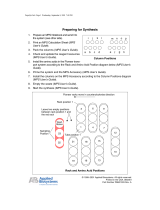
Program for Super Chlorination 128
Program for Dechlorination 129
Program for Auto Fill 130
Program for chemical Storage
Tank Auto Fill 130
Program for pH 131
Program for PPM 132
Program for Temperature 132
CONTENTS

4
ACU-TROL® AK600 Chemical Controller Installation and User's Guide
Most states and local codes regulate the construction, installation, and operation of
public pools and spas, and the construction of residential pools and spas. It is important
to comply with these codes, many of which directly regulate the installation and use
of this product. Consult your local building and health codes for more information.
SERIOUS BODILY INJURY OR DEATH CAN RESULT IF THIS PRODUCT IS NOT INSTALLED
AND USED CORRECTLY.
INSTALLERS, POOL OPERATORS AND POOL OWNERS MUST READ THESE WARNINGS AND
ALL INSTRUCTIONS BEFORE USING THIS PRODUCT.
IMPORTANT NOTICE - Attention Installer: This Installation and User’s Guide
(“Guide”) contains important information about the installation, operation and safe use
of this product. This Guide should be given to the owner and/or operator of this product.
DO NOT INSTALL THE CHEMICAL CONTROLLER WHERE IT CAN BE
READILY ACCESSIBLE TO THE PUBLIC.
Before installing this product, read and follow all warning notices and instructions in this
Guide. Failure to follow warnings and instructions can result in severe injury, death, or
property damage. Call (800) 831-7133 for additional free copies of these instructions.
BEFORE WORKING ON THE CHEMICAL CONTROLLER: Always disconnect power to
the controller at the circuit breaker before servicing. Failure to do so could
result in death or serious injury to service person, pool users or others due to electric
shock.
RISK OF ELECTRICAL SHOCK OR ELECTROCUTION:
This product must be installed by a licensed or certified electrician or a qualified pool professional in accordance
with the National Electrical Code (NEC), NFPA 70 or the Canadian Electrical Code (CEC), CSA C22.2. All
applicable local installation codes and ordinances must also be adhered to. Improper installation will create an
electrical hazard which could result in death or serious injury to pool users, installers or others due to electrical
shock, and may also cause damage to property.
Do not permit children to operate this equipment.
When mixing acid with water, ALWAYS ADD ACID TO WATER. NEVER ADD WATER TO ACID.
When adding any chemical to the pool/spa, be sure to follow the manufacturer’s instructions
thoroughly.
DO NOT MIX SODIUM HYPOCHLORITE AND MURATIC ACID
Risk of electrical shock. Connect the Chemical Controller to a ground-fault interrupter-
circuit (GFCI). Contact a qualified electrician if you cannot verify that the receptacle is protected
by a GFCI.
BE SURE TO DISCONNECT ALL SUPPLY CONNECTIONS BEFORE SERVICING.
BEFORE USING YOUR POOL, SPA OR HOT TUB, CHECK THE
pH AND SANITIZER LEVELS OF THE WATER.
DISABLING THE OVERFEED TIMERS USING THE “CLEAR OVERFEED LIMITS” OR FLOW
SWITCH
GREATER THAN 20 HOURS AS THIS WILL VOID NSF CERTIFICATION.
IMPORTANT WARNING AND SAFETY INSTRUCTIONS
IF “CLEAR OVERFEED LIMIT” SETTING IS SET TO 24 HOURS, DO NOT SET “FEED TIME”
WILL VOID NSF CERTIFICATION.

5
ACU-TROL® AK600 Chemical Controller Installation and User's Guide
WARNING
CHEMICAL BURN HAZARD
Make sure pumps are OFF before drilling into pipes.
Securely fasten all electrical, water and chemical lines. Locate chemical feed
pumps and chemical storage tanks in a safe and secure area.
PLEASE READ THIS USER MANUAL completely before installing or operating the equipment. The Controller Pool and Spa Chemical
Controller is a Class 1 product for protection against electric shock and a Type 1 product with regards to disconnection of the control circuits.
Be sure to observe the following safety precautions:
• Donotpermitanyoneuntrainedorundertheageof18tousethisproduct.
• Unitmustbeproperlygrounded.
• Frontpanelmustbeclosedbeforepowerisapplied.
• AlwaysturnOFFmaincircuitbreakertounitandallequipmentbeforeservicing.
• Touchingthecontroller’sinternalpartscouldresultininjuryandordamagetothecontroller.Incaseofa
malfunction, only a qualified technician should repair the controller.
• RiskofElectricShock.Connectonlytoagroundingtypereceptacleprotectedbyaground-faultcircuitinterrupter(GFCI).
• Donotburycord.Routecordtoeliminateexternaldamage.
• Becarefulnottodamageanyoftheinsulationonwiresorthepowercord.Shouldthecordbedamaged,returnittoyourdealerfor
a replacement. Continued use could result in fire or electric shock.
• Toreducetheriskofelectricshock,donotuseanextensioncordtoconnectunittoelectricsupply,providea
properlylocatedGFCI.
• Neverremoveorinstallanycablesonthecircuitcardswhenpowerisapplied,damagetothecomponentsmay
occur.
GENERAL WARNINGS AND SAFETY PRECATIONS
!
WARNING
CHEMICAL HAZARD CONDITION
DO NOT TURN CHEMICAL FEED PUMPS ON WHEN BOTH FLOW
CELL VALVES ARE CLOSED.
!
WARNING CHEMICAL BURN HAZARD: Make sure all pumps are switched off at the main circuit
breakers at the house before drilling into any pipes. Securely fasten all electrical, water and
chemical lines. Locate chemical feed pumps and chemical storage tanks in a safe and secure
area.
Strictly follow the acid manufacturers safety and handling protocols including hand, body and eye protection
when transferring or handling acid. Safety precautions should be used when handling Muriatic acid to
control pH water levels. Muriatic acid can cause serious body injury and damage pool equipment. Extra
care must be taken when installing, maintaining and operating acid pump feed systems. Acid is dangerous to
handle and should be properly contained, transported, poured, stored, and dispensed.
Check the pH and sanitizer levels of the water before use.
Periodically use an independent pH and Chlorine test kit to verify that pH and chlorine is at a
safe level. If the pH and Oxidation Reduction Potential (ORP) or Flow Cell sensors are broken,
depleted or dirty with oils, lotions, or other contaminants, they can report inaccurate results to the
system causing incorrect water chemistry, which could harm people or equipment.
Check the IntelliChem main status display each day to ensure there are no Alarm messages.
See “Troubleshooting” section for more information.installing, maintaining and operating acid
pump feed systems. Acid is dangerous to handle and should be properly contained, transported,
poured, stored, and dispensed.
IMPORTANT WARNING AND SAFETY INSTRUCTIONS

6
ACU-TROL® AK600 Chemical Controller Installation and User's Guide
Controller Chemical Controller Installation Conguration
WARNING
For 230 VAC Power the Controller Input Voltage Selection Switch MUST be changed from 115
VAC to 230 VAC or damage will occur to the Controller. This damage is NOT covered by the
warranty. Do NOT connect any load not rated for the supply voltage to any of these relays.
Exploded View
!

7
ACU-TROL® AK600 Chemical Controller Installation and User's Guide
DWG. # PART # DESCRIPTION
1 Enclosure, Controller, lid, overlay, and hardware
2 714000720 Kit, Controller, Power Switch
3 755000190 Cord, Power, Controller, GFCI
** Not permitted in all areas**
4 714000110 Strain Relief, 5/8”, liquid tight
5 714000100 Strain Relif, 1/2”, liquid tight
6 724000120 PCB, Relay Board, Controller, 4 NO
7 724000130 PCB, Sensor, pH, ORP, Temp, 3 switch
8 724000090 PCB, Motherboard, Controller
9 724000100 PCB, Interface Board, Controller
10 724000110 Display, Touchscreen, Controller
11 Ribbon Cable, Controller
12 Relay board mounting screws
13 724000050 Socket, Relay NO(110/24/Dry)
14 714000120 Kit, latch, Integra Enclosure
Not Shown
725000020 Modem, Standard
735000010 Modem, Wireless
724000150 PCB, Sensor, Pressure, Temp
724000160 PCB, Sensor, pH, ORP, Cond, Temp
724000180 PCB, Sensor, pH, ORP, Color, Temp
724000190 PCB, Sensor, pH, ORP, Color, Cond, Temp.
724000060 Socket, Relay, NC (110/24/Dry)
Parts List
ORP and pH Sensor Replacement Part Numbers
ORP SENSOR P/N 744000340
PH SENSOR P/N 744000260

8
ACU-TROL® AK600 Chemical Controller Installation and User's Guide
Controller CHEMICAL CONTROLLER OVERVIEW
Acu-Trol®, a technological leader in swimming pool automation, congratulates you on
your selection of the Controller Chemical Controller ("Controller") swimming pool
controller. The Controller will maintain the pH and sanitizer levels, maintain a set
temperature, and control up to 16 external devices in a pump room, on up to three
pools or spas. The Controller is specically designed to be easy to use and install
while meeting the needs of the most demanding applications.
The Controller Chemical Controller features:
MODULAR DESIGN: The Controller is designed to grow with your needs.
Increase the number of bodies of water, add true PPM control, conductivity control,
or add additional relays to automate your pump room. The Controller can be easily
modied at the installation site with only a few basic tools.
INTERFACE: The Controller uses a touch screen display panel with a built in
graphical user interface for simple operation. A full alphanumeric keyboard is
available for easy calibration and programming. An automatic backlight ensures clear
visibility of the touch panel, and conserves power by turning on only when the touch
screen is in use.
MEMORY: The Controller has built-in memory that automatically saves your
programming. If your controller ever loses power, it will retain all programmed
values.
DATA RECORDING: The Controller has the ability to record data from all sen-
sors and to store up to 6505 measurement lines, the equivalent of 271 days of hourly
recordings.
CALCULATED READINGS: The Controller calculates and displays the free
available chlorine, scaling index values for each body of water, and two (2) differen-
tial readings based on the four (4) pressure sensors.
RELAYS: The ability to control up to 16 relay modules enables the Controller to
automate nearly every device in your pump room. There are various types of relay
module congurations available to meet most load requirements.
DETAILED DISPLAY: In addition to the chemical readings, the Controller will
display important information about the relays controlling each device. It will tell your
operator whether each relay is currently on or off, how long each relay has been on,
and any relays that have reached their programmed time limits and are now in alarm.
SENSORS: The Controller can interpret readings from many types of sensors,
allowing you to measure pH, ORP, true PPM, Temperature, pressure, and conductivity.
Each sensor has it's own unique circuitry, isolating it for more exact measurements.
VOLTAGE: The Controller can be congured to use either 115 VAC or 230 VAC.
This allows the controller to be plugged in to an existing outlet, or wired directly in to
the electrical system.

9
ACU-TROL® AK600 Chemical Controller Installation and User's Guide
The Controller Installation, Operation and Programming Guide explains the proce-
dures for proper installation and operation. Section one (1) the installation guide,
consists of Sections 2, 3, 4, and 5, and introduces the parts of the controller and the
process to follow when installing the electrical and plumbing portions.
Section two (2) the operation guide, consists of Section 6, and describes all the avail-
able screens and menus of the controller, from navigating and initializing the screens
to programming and customizing specications. Section three (3) the programming
guide, consists of Sections 7, 8, 9, 10, 11, and 12, and describes troubleshooting
strategies, optional devices that may be added to your Controller, and many of the
relevant charts and diagrams..
A chemical controller is designed to maintain specic levels of disinfecting and
balancing chemicals. Disinfecting chemicals help to control the growth of bacteria and
other organisms in the water of a pool or spa. Balancing chemicals keeps a pool or
spa at a certain pH level, preventing the water from becoming acidic, and corroding
the pool and its equipment, or becoming basic, and causing buildup on the equip-
ment.
Water maintenance is an important part of operating a pool and spa. Pool oper-
ators should be trained in water maintenance by an authority recommended by their
local health department. Water maintenance requirements are generally determined
by the county or state and can vary widely. However, most requirements fall within
the following range recommended by the National Swimming Pool Foundation:
Filtration: Minimum turnover rate of six hours for a pool and
30 minutes for a spa.
Water Balance: – pH 7.2 – 7.6, alkalinity 80-120 PPM.
Oxidation Reduction Potential (ORP) – A reading of 650 mV - 750 mV.
Total Dissolved Solids - Should not exceed 2000 PPM.
(excluding pools using a salt chlorine generator)
This information is meant to provide pool operators with a basic idea of the
range of water maintenance requirements, and the importance of water maintenance.
To ensure that your facility is in compliance with all local regulations please check
with your local health department.
The Importance of Water Maintenance
Technical Support
Phone: (800) 831-7133 - Fax: (800) 284-4151
visit www.pentairpool.com and www.staritepool.com:

10
ACU-TROL® AK600 Chemical Controller Installation and User's Guide
Section 2 Installation
Installation Preparation
As soon as your controller is delivered, inspect the shipping carton carefully for
damage. Report any damage directly to the shipping company. Compare the
packing list to the contents of the carton. If anything is missing contact your local
Acu-Trol dealer. Use care when unpacking equipment to avoid damage or loss of
small parts.
We strongly recommend that you plan out the pool room layout before you install
the Controller Chemical Controller. Figure 1 is a sample of a pool room layout. Your
layout will vary depending on your equipment, the size of your room, etc. It is
important to mark and plan all electrical and plumbing connections before making
changes to the existing system.
Drain Flow
Flow
Flow
Flow
Flow
Flow
Flow
Chlorine
Acid
Power
Signal
Water
Gas
Chemical
Pool
Figure 1. Controller Chemical Controller System

11
ACU-TROL® AK600 Chemical Controller Installation and User's Guide
The modular design of the Controller allows the connection and control of any
device to any relay. Determine which device you want to connect to each relay or
input before you begin the installation process. For Controller can control multiple
bodies of water. I it helpful if the conguration for each body of water is the same:
i.e. your pH pump is always connected to relay 1.
Below are Relay and Input Mapping Tables to help in the planning and organiza-
tion of new installations. Use these tables to record your input and relay congu-
rations. This information will be valuable when the system has an alarm, or when
you choose to upgrade the system to control an additional body of water.
INPUT NAME SYSTEM NAME INPUT USED FOR
PH1 Kids Pool Flow cell measurement for acid feed control
ORP1 Kids Pool Flow cell measurement for Cl feed control
Temp1 Kids Pool Flow cell measurement for heater control
FL1 Kids Pool Flow cell magnet indicates ow
RELAY SYSTEM NAME RELAY USED FOR VOLTAGE
1 Kids Pool Acid Feed Pump 115VAC
2 Kids Pool Erosion Feeder Solenoid 24VAC
3 Kids Pool
4 Kids Pool Heater Control Dry
To simplify the installation process, Acu-Trol manufactures the Controller with de-
fault factory relay and input congurations. The factory default settings are stored
in the controller and can be reloaded at any time.
Example Input Table
Example Relay Table

12
ACU-TROL® AK600 Chemical Controller Installation and User's Guide
Site Name _________________________________________________________
Input Mapping Table
INPUT NAME SYSTEM NAME INPUT USED FOR
Relay Mapping Table
RELAY SYSTEM NAME RELAY USED FOR VOLTAGE
1
2
3
4
5
6
7
8
9
10
11
12
13
14
15
16
VOLTAGE: In most cases, the devices attached to the controller will use the same
voltage as the Controller. A controller congured to use 115 VAC will not be able
to run devices requiring 230 VAC, and vice versa. The Controller relay modules will
switch the module’s voltage to the load to turn it ON and disconnect the voltage
from the load to turn it OFF.

13
ACU-TROL® AK600 Chemical Controller Installation and User's Guide
The following steps are required to completely install an Controller Chemical
Controller:
1. Identify new and existing equipment to be connected.
2. Decide if the sensors will be in-line, in a separate by-pass line, or if the
AK1200 ow cell will be used.
3. Determine the supply voltage, 115 VAC or 230 VAC, and set the supply
voltage switch as necessary.
4. Determine if the control to the equipment uses the same voltage as the
supply voltage. All controlled equipment must be compatible.
5. Determine the plumbing locations for the ow cell bypass inlet and outlet.
6. Mount the Controller away from direct sunlight and on a at vertical
surface.
7. Connect the supply voltage with main breaker off
(Must be a separate dedicated circuit GFCI).
8. If using an AK1200 ow cell install the bypass now.
9. Connect the sensors.
10. Test the plumbing for leaks.
11. Turn on/plug in the Controller for the rst time.
12. Test the equipment, using the Controller manual relay mode.
13. Calibrate the probes, then recalibrate as the probes acclimate to the
water. Acclimation can take as little as two hours or as long as 24 hours.
14. Program the Controller.
15. Call or visit the controller over the next few days to insure the system is
balanced and in control. Fine-tune the setup if necessary.
Installation Overview
CAUTION
If the AK1200 is used, the input water maximum pressure is 25 PSI.

14
ACU-TROL® AK600 Chemical Controller Installation and User's Guide
Mounting the Controller Chemical Controller
Select a location for mounting the Controller that will meet the following condi-
tions:
• At least ten (10) feet from open water.
• Supply power must be routed to the Controller in accordance with the
applicable codes in the area; the supplied cord is not code in some areas. Please
have a licensed electrician perform any and all electrical.
• The installation surface must be solid and vertical.
Do not mount the controller in a horizontal position.
WARNING
Proper and safe operation requires an earth ground connection.
• Maintain adequate clearance for opening the enclosure door.
• The environment should be free of chemical fumes and excessive heat.
Do not install the Controller in areas that exceed 110° Fahrenheit.
• Mount the controller as far as possible from potential sources of electrical in-
terference. To mount the Controller to your chosen surface:
• Attach the four (4) mounting
brackets to the back of the controller,
using the supplied hardware.
• Hold the controller against the
mounting surface with the lid closed
and mark the four (4) holes located
in the top and bottom bracketscon-
nected to the controller.
• Prepare holes as necessary and
secure controller.
• Make sure the controller box is
not
WARNING
Keep the Controller out of direct sunlight and inside a room if possible, a
shade screen should be used for outdoor installations.

15
ACU-TROL® AK600 Chemical Controller Installation and User's Guide
Every Controller Chemical Controller installation will be different depending on the
type of equipment you have, the plumbing that already exists, and the amount of
available room for the installation. It is strongly suggested that you create an installa-
tion plan for the plumbing and the controller. This section gives the basic principles to
be applied for any specic installation, which are listed as follows:
• Turn OFF all equipment.
• Determine a suitable location for the AK1200 Flow Cell.
(See ow cell manual for detailed setup instructions).
• Securely mount the AK1200.
• Locate where the water will be supplied from and returned to each AK1200.
• Install the supply and return lines for each AK1200.
• Locate the chemical injection points.
• Prepare and install the chemical injectors.
• Install the chemical storage containers.
• Install the sensors.
• Turn on the main circulation pump.
• Check for leaks.
• Verify ow switch magnet in AK1200 is being pushed up with the ow.
• Verify the AK1200 is not under any vacuum by opening the bottom sample valve.
A stream of water should be released. If no water is released, and you see bubbling
around the sample port, close the AK1200 outlet valve until the bubbling stops and a
stream of water is released from the sample port.
• Leave the 1200 ow cell full of water to allow sensors to begin acclimating to sys-
tem water.
• Call or visit several times over the next few days to verify system integrity
2.4 Plumbing Installation
WARNING
To ensure that your installation complies with all local codes have
a licensed plumber complete all plumbing installations.

16
ACU-TROL® AK600 Chemical Controller Installation and User's Guide
Each electrical installation for the Controller Chemical Controller is different de-
pending on the electrical codes in your local area, the types of devices you want
the Controller to control, and the existing wiring in your facility. While we are un-
able to provide you with specic advice regarding your installation, we do suggest
that you follow these basic steps.
• Identify the new and existing equipment to be connected.
• Determine the supply voltage, 115 VAC or 230 VAC and if an external ON/OFF
switch is necessary.
• Determine if the equipment control voltage and supply voltage are the same.
• Connect the supply voltage. (Must be on a separate dedicated GFCI circuit)
• Connect each load to the corresponding relay.
• Connect the sensors. Route the sensor wires through the three small strain
reliefs’ into the controller and install them in to the appropriate connectors in the
sensor module.
• The polarity (+ and -) of the pH and ORP sensors must be observed.
• The ORP sensor (+) is marked ORP+
• The pH sensor (+) is marked pH+
• The green leads are (-) polarity.
• Do not cut the sensor wires.
• After the wiring is complete, close the panel and tighten the strain reliefs’. Wrap
and tie any excess wire into a coil.
• Do not stuff excess wire inside the controller.
• Test the equipment, using the Controller manual relay mode.
Electrical Installation
CAUTION
To ensure compliance with all state and local codes, have a
licensed elecctrican perform any and all electrical work.
!

17
ACU-TROL® AK600 Chemical Controller Installation and User's Guide
The Controller Chemical Controller operates on input voltages of 115 VAC or 230 VAC.
The factory default input voltage is set for 115 VAC. The supply power is most com-
monly used to power the feed pumps and other external loads. If all the loads are
115 VAC then use 115 VAC and if all the loads are 230 VAC then use 230 VAC as the
input voltage. It is also possible to have one relay board powered with 115 VAC and
another relay board with 230 VAC. This is benecial when there is a mix of load volt-
ages. If you need to have your relay boards use different input voltages please con-
tact your local Acu-Trol dealer for further instructions and assistance.
Input Voltage Selection
ITEM DESCRIPTION LIMIT
Input Voltage Maximum Input AC Voltage 250 VAC
Input Current Maximum Current for All Relays 10 Amps VAC per relay board
Input Current Maximum Current for Single Relays 5 Amps VAC
Temperature Minimum/Maximum Operating Temp 30-110 ºF
Standby Current
Current with all relays OFF, LED ON
Current with all relays OFF, LED OFF
90 mA (AC) Typical
65 mA (AC) Typical
Sensor Range
pH
ORP
Temp
AKColor PPM
4.2-9.8 pH units
0-999 mV
32 – 212ºF
0 – 8 PPM
Electrical Limits for the Controller
Chemical Controller
WARNING
If the Controller Chemical Controller is conntected to 230 VAC the voltage
switch on the relay board must be changed to 230 VAC.

18
ACU-TROL® AK600 Chemical Controller Installation and User's Guide
Controller Chemical Controller Installation Conguration
WARNING
For 230 VAC Power the Controller Input Voltage Selection Switch MUST be
changed from 115 VAC to 230 VAC or damage will occur to the Controller. This
damage is NOT covered by the warranty. Do NOT connect any load not rated
for the supply voltage to any of these relays.
Illustrated Parts View
!

19
ACU-TROL® AK600 Chemical Controller Installation and User's Guide
DWG. # PART # DESCRIPTION
1 Enclosure, Controller, lid, overlay, and hardware
2 714000720 Kit, Controller, Power Switch
3 755000190 Cord, Power, Controller, GFCI ** Not permitted in all ar-
eas**
4 714000110 Strain Relief, 5/8”, liquid tight
5 714000100 Strain Relif, 1/2”, liquid tight
6 724000120 PCB, Relay Board, Controller, 4 NO
7 724000130 PCB, Sensor, pH, ORP, Temp, 3 switch
8 724000090 PCB, Motherboard, Controller
9 724000100 PCB, Interface Board, Controller
10 724000110 Display, Touchscreen, Controller
11 Ribbon Cable, Controller
12 Relay board mounting screws
13 724000050 Socket, Relay NO(110/24/Dry)
14 714000120 Kit, latch, Integra Enclosure
Not Shown
725000020 Modem, Standard
735000010 Modem, Wireless
724000150 PCB, Sensor, Pressure, Temp
724000160 PCB, Sensor, pH, ORP, Cond, Temp
724000180 PCB, Sensor, pH, ORP, Color, Temp
724000190 PCB, Sensor, pH, ORP, Color, Cond, Temp.
724000060 Socket, Relay, NC (110/24/Dry)
Parts List

20
ACU-TROL® AK600 Chemical Controller Installation and User's Guide
Controller Chemical Controller Inputs & Outputs
Follow the instructions included with the chemical feed pump for installation if it is not
already installed. Follow the list below for location recommendations:
• Mount at least 10 feet from open water.
• Close enough to the Controller for the feed pump power cords to reach.
• Remove the electric plugs from the feed pumps and strip the ends.
• Route the power cords to the Controller through the lower ttings and attach to
the appropriate relay terminals on the appropriate relay module boards.
• Conduit or external plugs can also be used (according to the codes in the local
area).
• When installing metal conduit into the controller, a ground LUG should be used to
connect the conduit to the relay board ground.
Chemical Feed Pump Installation
/