Page is loading ...

SWITCH INSTALLATION:
1. Locate an accessible position for the 12V DC switch in
cabinet just above or beside the refrigerator door. A
location near the left, upper corner is recommended.
2. Cut a rectangular hole (.550 x 1.125) so that the 12V
DC switch can be installed. Do not cut the hole larger
than necessary or the switch will not be retained.
3. Attach the enclosed red wire assembly and the red wire
from the fuse assembly (wire with 1/4 terminal) to
switch. Route wires through the opening and install the
switch. Be sure that wires extend to the rear of the
refrigerator compartment.
VENTILATOR FAN INSTALLATION (A or B):
1. Install fan limit switch to the refrigerator per location
requirements and dimensions given in FIG. 1.
A. Screws: Use care when drilling two (2) .110 (7/64”)
diameter holes for the #6 x 3/8” screw attachment.
B. Epoxy: A quick-drying epoxy has been provided to
attach the fan switch to the condenser fin. Be sure
you are ready to install the switch when mixing
the epoxy since it will set in 3-5 minutes. Place
the epoxy on the switch around the screw loca-
tions. Place the switch on the condenser in the
proper location and hold in place until set. Add
additional epoxy as necessary. Allow 15-20 min-
utes dry-time before attachment of 1/4 quick con-
nect terminals.
Form No. 3107303.004 8/96
©1996 The Dometic Corp., LaGrange, IN 46761
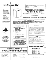
PURPOSE:
This Power Ventilator and Switch Assembly is for use with
Dometic’s single-door refrigerators in applications where
existing minimum vent heights are restricted. Its purpose is
to assist required air movement across the refrigerator
condenser to ensure optimum performance.
The switch mechanism allows the customer to turn off
power to the ventilator fan when the vehicle is not being
used to ensure that the vehicle battery is not depleted due
to the automatic operation of the fan.
GENERAL INSTRUCTIONS:
Read and understand these instructions before pro-
ceeding.
Disconnect all electrical power before starting
your power ventilator installation.
These instructions are only supplemental. If your refrig-
erator has not yet been installed, do so per the product
installation instructions. Make sure that you follow N.E.C.,
state and local code requirements that are referenced in
your original installation instructions. Follow the compart-
ment sealing instructions as indicated in your instruction
packet.
POWER VENTILATOR AND SWITCH ASSEMBLY
PART NO. 3107316.006
FOR SINGLE DOOR ABSORPTION REFRIGERATORS
Patent No. 5355693
This Assembly Contains:
Qty. Part No. Description
(1) 3104132.000 Ventilator Fan, 12V DC
(1) 3104133.008 Fan Limit Switch, 12V DC
(2) 312096.002 Screw #6 x 3/8
(2) 3102096.001 Screw #10 x 3.8
(1) 3105432.003 Mounting Bracket, RH
(1) 3105432.011 Mounting Bracket, LH
(1) 3105503.005 Fuse Holder and Fuse (1 amp)
(2) 3102096.025 Screw, #6 x 1-1/2
(1) 3107303.004 Installation Instructions
(1) 303937.856 Wire Assembly, Red
(1) 3107315.008 Switch Assembly
(1) 3107314.001 Quick Dry Epoxy
THIS ASSEMBLY SHOULD BE INSTALLED BY A QUALIFIED SERVICE
PERSON WHO IS FAMILIAR WITH ELECTRICAL WIRING.

FIG. 1A
7. Route red wire assembly with fuse body from ON/OFF
switch near the previously removed fuse connection.
8. Take the other red wire assembly from the ON/OFF
switch and attach to the fan limit switch.
9. Take the red wire attached to the ventilator fan and
route to the remaining terminal at the fan limit switch.
10. Take the black wire from the ventilator fan and route
to the 12V DC– (negative) connection on the incoming
side of the refrigerator terminal block.
11. Ensure that all wiring is held securely and will not come
in contact with a sharp edge or hot surface.
12. Install fuse within fuse holder.
13. The power ventilator will be energized by the fan limit
switch when the temperature elevates above 95° am-
bient. This system will operate automatically with the
fluctuation of the condenser temperature when the 12V
DC switch has been turned on.
14. When refrigerator is not in operation, turn switch to
“OFF” position to avoid depleting the battery.
NOTE
Take caution to ensure epoxy is not placed on the
sensing part of the limit switch.
2. Install air baffle the width of the refrigerator cavity. This
should extend to the bottom edge of the condenser
fins. See FIG. 1A.
3. Install mounting brackets to ventilator fan per FIG. 1A,
with #6 x 1-1/2” screws provided.
4. Install fan in upper vent as shown in FIG. 1A (NOTE:
Ensure that air flow is pointing outward.) Fan
should be located facing outside wall structure, cen-
tered to vent opening.
INSTALLATION THROUGH LOWER VENT:
5. Remove fuse in fuse holder and store in safe location
for later installation.
6. Route fuse holder base red wire (shortest wire) to the
12V DC+ (positive) connection on the incoming side of
the refrigerator terminal. DO NOT REINSTALL FUSE
AT THIS TIME).
C
L
2"
3/4"
FIG. 1
/