Bradford White D-80T-425-3N User manual
- Category
- Water heaters & boilers
- Type
- User manual

238-47675-00E 2/17
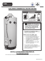
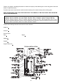
GAS-FIRED COMMERCIAL WATER HEATER
INSTALLATION/OPERATION MANUAL
WITH TROUBLESHOOTING GUIDE
PLACE THESE INSTRUCTIONS ADJACENT TO WATER HEATER AND NOTIFY OWNER TO KEEP FOR FUTURE REFERENCE
- Do not store or use gasoline or other
flammable vapors and liquids in the vicinity
of this or any other appliance.
- WHAT TO DO IF YOU SMELL GAS
Do not try to light any appliance.
Do not touch any electrical switch; do
not use any phone in your building.
Immediately call your gas supplier from
a neighbor’s phone. Follow the gas
supplier’s instructions.
If you cannot reach your gas supplier,
call the fire department.
- For your family’s comfort, safety and
convenience, it is recommended this water
heater be installed and serviced by a
plumbing professional.
WARNING: If the information in
these instructions is not followed
exactly, a fire or explosion may
result causing property damage,
personal injury or death.

2
SECTION I: IMPORTANT INFORMATION
This water heater has a limited warranty. The warranty for this water heater is valid only if the water heater has been
installed, maintained and operated in accordance with these instructions. The warranty does not cover damage or
injury caused by the use of any energy-saving devices (other than those authorized by the manufacturer) in
conjunction with this water heater. The use of unauthorized energy-saving devices may decrease the life of the
water heater and endanger life and/or property. The manufacturer will not be liable for any damage, injury, or loss of
life resulting from alteration and/or failure to comply with these instructions.
IMPORTANT-Before proceeding, please inspect the water heater and components for possible damage. DO NOT
install damaged components. If damage is evident, please contact the supplier where the water heater was
purchased or the manufacturer listed on the rating plate for replacement parts.
NOTICE
I IMPORTANT INFORMATION..........................2 VIII ELECTRICAL CONNECTIONS.....................21
II SPECIFICATIONS............................................5 IX OPERATING INSTRUCTIONS......................23
III GENERAL INFORMATION..............................8 X MAINTENANCE.............................................32
IV INSTALLATION INSTRUCTIONS..................10 XI
DIAGNOSTIC AND TROUBLESHOOTING
GUIDE............................................................34
V VENTING........................................................15 XII PARTS LIST...................................................54
VI WATER CONNECTIONS……………………..17 XIII
INSTALLATION FOR POTABLE
WATER AND SPACE HEATING...................55
VII GAS CONNECTIONS....................................19 XIV NOTES………………………………………….56
TABLE OF CONTENTS
This gas-fired water heater is design certified by CSA International under the American National Standard, Z21.10.3
and CAN/CGA 4.3-M (as indicated on the rating plate). These standards are available from CSA Standards
Association, 5060 Spectrum Way Mississauga, Ontario L4W 5N6 CANADA.
This water heater must be installed in accordance with local codes. In the absence of local codes, it must be
installed in compliance with the National Fuel Gas Code (ANSI Z223.1-Latest Edition), or in Canada CAN/CGA
B149.1 Natural Gas Installation Code (Latest Edition) or CAN/CGA B149.2 Propane Installation Code (Latest
Edition).
The following terms are used throughout this manual to bring attention to the presence of hazards at various risk
levels, or to important information concerning product life.
READ CAREFULLY
Indicates special instructions on installation,
operation or maintenance, which are important but
not related to personal injury hazards.
NOTICE
Indicates a potentially hazardous situation, which, if
not avoided, could result in death, serious injury or
substantial property damage.
WARNING
Indicates potentially hazardous situation, which, if not
avoided, may result in moderate or minor injury or
property damage.
CAUTION
Indicates an imminently hazardous situation, which, if
not avoided, will result in death, serious injury or
substantial property damage.
DANGER

3
DANGER
DO NOT store or use gasoline or other flammable, combustible, or corrosive vapors and/or liquids in the vicinity of
this or any other appliance.
This water heater is equipped with an adjustable thermostat to control water temperature. Hot water temperatures
required for automatic dishwasher and laundry use can cause scald burns resulting in serious personal injury and/or
death. The temperature at which injury occurs varies with the person’s age and the time of exposure. The slower
response time of disabled persons increases the hazards to them. NEVER allow small children to use a hot water tap,
or to draw their own bath water. NEVER leave a child or disabled person unattended in a bathtub or shower.
Toxic chemical, such as those used for boiler treatment, must not be introduced into potable water used for space
heating.
This water heater must not be connected to an existing heating system or component(s) previously used with a non-
potable water heating appliance.
All piping components connected to this water heater for space heating applications must be suitable for use with
potable water.
WARNING
Improper installation, adjustments, alteration, service or maintenance can cause property damage, personal injury or
loss of life. Failure to follow all instructions in the proper order can cause personal injury or death. Read and
understand all instructions, including all those provided with the appliance before installing, starting-up, operating,
maintaining or servicing this appliance. Keep this manual and literature in legible condition with this water heater for
reference by owner and service technician.
This water heater requires regular maintenance and service to operate safely. Follow the instructions contained in this
manual.
Installation, maintenance, and service must be performed only by a qualified, skilled and knowledgeable installer or
service provider.
Installation is not complete unless a temperature and pressure relief valve is installed into the proper location at the
top of this water heater.
It is the responsibility of the installing contractor to see that all controls are correctly installed and are properly
operating when the installation is complete.
DO NOT operate this water heater without first being certain it is filled with water.
DO NOT tamper with or alter the water heater and/or controls.
DO NOT operate water heater with jumpered or absent controls or safety devices.
DO NOT operate water heater if any external part has been under water. Immediately call a qualified service
technician to inspect the appliance and to replace any part of the control system including gas controls, which has
been under water.
DO NOT attempt to use this water heater with any gas other than the type listed on the rating plate. Do not attempt to
convert this water heater for use with a gas other than the type for which it is equipped. Failure to use the proper gas
can create an unsafe condition resulting in property damage, bodily injury, or death. Consult your local gas supplier or
gas company if there are any questions.
For installations in high altitude regions, this water heater must be ordered from the supplier to the manufacturer’s
specifications for that particular altitude. Contact the company listed on the rating plate when ordering high altitude
constructed water heaters.
Incorrect operation of this appliance may create a hazard to life and property and will nullify the warranty.
DO NOT operate this water heater if the input rate exceeds the rate shown on the water heater rating plate.
This water heater contains very hot water under high pressure. Do not unscrew any pipe fittings nor attempt to
disconnect any components of this water heater without positively assuring the water is cool and is not under
pressure. Always wear protective clothing and equipment when installing, starting up or servicing this water heater to
prevent scald injuries. Do not rely on the temperature gauges to determine the temperature. Do not touch any
components unless they are cool.
This water heater must be properly vented and connected to an approved vent system in good condition. DO NOT
operate water heater with the absence of an approved vent system. A clean and unobstructed vent system is
necessary to allow noxious fumes that could cause injury or loss of life to vent safely and will contribute toward
maintaining the water heater’s efficiency.

4
WARNING
This water heater needs fresh air for safe operation and must be installed so there are provisions for adequate
combustion and ventilation air. Insufficient air supply will cause a recirculation of combustion products resulting in
contamination that may be hazardous to life. This will result in carboning or sooting of the combustion chamber,
burners, and flue tubes and creates a risk of asphyxiation.
Water heater materials of construction, products of combustion and the fuel contain carbon monoxide, nitrogen
oxides, aldehydes and/or other toxic or harmful substances which can cause death or serious injury and which are
known to the state of California to cause cancer, birth defects and other reproductive harm. Always use proper safety
clothing, respirators and equipment when servicing or working nearby this water heater.
Flammable items, pressurized containers or any other potential fire hazardous articles must never be placed on or
adjacent to the water heater. Open containers of flammable material should not be stored or used in the same room
with this water heater.
Insulation blankets are not required for this water heater. This water heater meets or exceeds the ASHRAE/IES 90.1b
(latest edition) standards with respect to insulation and standby loss requirements.
Setting the water temperature to the maximum set point can result in scalding hot water delivered to the faucets. It is
highly recommended that the maximum setpoint be adjusted to the lowest temperature possible for the needs of the
installation. See following section in this Installation/Operation Manual to change the maximum setpoint limit (max
setpoint). Make sure the water heater control display is not in a public area that can result in the temperature settings
being improperly adjusted.
Hydrogen gas can be produced in an operating water heater that has not had water drawn from the tank for a long
period of time (generally two weeks or more). Hydrogen gas is extremely flammable. To prevent the possibility of
injury under these conditions, we recommend the hot water faucet to be open for several minutes at the kitchen sink
before you use any electrical appliance, which is connect to the hot water system. If hydrogen is present, there will be
unusual sounds such as air escaping through the pipes as hot water begins to flow. Do not smoke or have open flame
near the faucet at the time it is open.
Do not use this appliance if any external part to the tank has been submerged in water. You should contact a qualified
service technician to inspect the appliance and to replace any part of the control system including the combination gas
control which has been submerged in water. See the Gas Connections section of this manual before servicing or
replacing a water heater that has had any external part to the tank submerged in water.
To comply with NSF requirements this water heater is to be:
a) Sealed to the floor with sealant, in a smooth and easily cleanable way, or
b) Installed with an optional leg kit that includes legs and/or extensions that provide a minimum clearance of 6”
beneath the water heater.
Liquefied petroleum gases/propane gas is heavier than air and will remain at floor level if there is a leak.
Basements, crawl spaces, closets and areas below ground level will serve as pockets for accumulation of leaking
gas. Before lighting, smell all around the appliance area for gas. Be sure to smell next to the floor.
IF YOU SMELL GAS:
DO NOT try to light any appliance.
DO NOT touch any electric switch; do not use any telephone in your building.
Immediately call your gas supplier from a telephone in another building. Follow the gas supplier’s
instructions.
If you cannot reach your gas supplier, call the fire department.
DO NOT OPERATE THE APPLIANCE UNTIL THE LEAKAGE IS CORRECTED!
WARNING
Prior to connecting the gas supply line to a gas fired water heater, ensure that the gas supply line does not have
moisture/water or dirt/scale inside the gas line. Commonly this check is done at the lowest point in the gas
distribution system prior to gas burning appliances.
WARNING

5
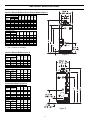
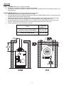
SECTION II: SPECIFICATIONS
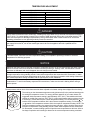
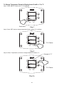
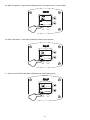
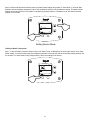
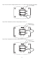
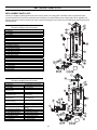
Non-Flue Damper Models and Flue Damper Models (Figure 1)
Model Description
A
(in)
B
(in)
C
(in)
D
(in)
E
(in)
F
(in)
Capacity
(GAL)
Input (BTU/hr)
Nat. LP
100 199,999 199,999 75.00 64.75 56.50 4.63 23 6
100 250,000 250,000 75.00 64.75 56.50 4.63 23 6
100 270,000 N/A 75.00 64.75 56.50 4.63 23 6
100 300,000 300,000 75.44 64.75 56.50 4.63 23 7
80 399,999 375,000 71.50 60.25 51.50 10.25 N/A 8
80 450,000 425,000 69.00 60.25 51.50 10.25 N/A 10
80 505,000 475,000 69.00 60.25 51.50 10.25 N/A 10
Model Description
A
(cm)
B
(cm)
C
(cm)
D
(cm)
E
(cm)
F
(cm)
Capacity Input (kW/hr)
(Litres) Nat. LP
378.5 58.6 58.6 191 164 144 11.8 58.4 15.2
378.5 73.2 73.2 191 164 144 11.8 58.4 15.2
378.5 79.1 N/A 191 164 144 11.8 58.4 15.2
378.5 87.9 87.9 192 166 144 11.8 58.4 17.8
302.8 117.2 109.9 181 153 131 26.0 N/A 20.3
302.8 131.8 124.5 175 153 131 26.0 N/A 25.4
302.8 148.0 139.2 175 153 131 26.0 N/A 25.4
1. N/A - Denotes not available.
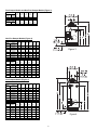
Non-Flue Damper Models (Figure 2)
Model Description
A
(in.)
B
(in.)
C
(in.)
D
(in.)
Capacity
(GAL)
Input
(BTU/hr)
65 370,000 71.38 64.75 54.13 8
65
399,999
(NAT ONLY)
71.38 64.75 54.13 8
75 300,000 72.00 65.75 54.13 7
80 425,000 81.00 75.50 64.50 10
80 505,000 81.00 75.50 64.50 10
Model Description
A
(cm)
B
(cm)
C
(cm)
D
(cm)
Capacity
(Litres)
Input
(kW/hr)
246.1 108.4 181 164 137 20.3
246.1
117.2
(NAT ONLY)
181 164 137 20.3
283.9 87.9 183 167 137 17.8
302.8 124.5 206 192 164 25.4
302.8 148.0 206 192 164 25.4
Flue Damper Models (Figure 2)
Model Description
A
(in.)
B
(in.)
C
(in.)
D
(in.)
Capacity
(GAL)
Input
(BTU/hr)
65 370,000 73.25 64.75 54.50 8
65
399,999
(NAT ONLY)
73.25 64.75 54.50 8
75 300,000 75.88 65.75 54.13 7
80 425,000 82.75 75.50 64.50 10
80 505,000 82.75 75.50 64.50 10
Model Description
A
(cm)
B
(cm)
C
(cm)
D
(cm)
Capacity
(Litres)
Input
(kW/hr)
246.1 108.4 186 165 138 20.3
246.1
117.2
(NAT ONLY)
186 165 138 20.3
283.9 87.9 193 167 138 17.8
302.8 124.5 210 192 164 25.4
302.8 148.0 210 192 164 25.4
Figure 1
Figure 2

6
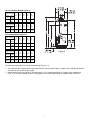
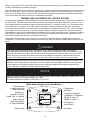
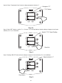
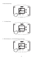
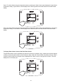
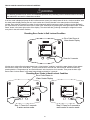
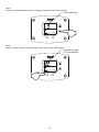
Flue Damper Models and Non-Flue Damper Models (Figure 3)
Model Description
A
(in.)
B
(in.)
C
(in.)
D
(in.)
E
(in.)
Capacity
(GAL)
Input
(BTU/hr)
38 155,000 51.00 43.50 35.00 33.75 6
Model Description
A
(cm)
B
(cm)
C
(cm)
D
(cm)
E
(cm)
Capacity
(Litres)
Input
(kW/hr)
143.9 45.4 130 110 89 86 15.2
Non-Flue Damper Models (Figure 4)
Model Description
A
(in.)
B
(in.)
C
(in.)
D
(in.)
E
(in.)
F
(in.)
Cap.
(GAL)
Input
(BTU/hr)
80 180,000 70.13 66.25 64.50 56.00 19.50 55.13
80 199,999 70.13 66.25 64.50 56.00 19.50 55.13
80
250,000
(235,000 LP)
70.13 66.25 64.50 56.00 19.50 55.13
98 199,999 81.13 77.25 75.50 67.00 19.50 66.13
98
250,000
(235,000 LP)
82.88 77.25 75.50 67.00 19.50 66.13
100 199,999 75.50 69.88 61.88 60.38 20.75 56.88
100 250,000 75.50 69.88 61.88 60.38 20.75 56.88
Flue Damper Models (Figure 4)
Model Description
A
(in.)
B
(in.)
C
(in.)
D
(in.)
E
(in.)
F
(in.)
Cap.
(GAL)
Input
(BTU/HR)
80 180,000 71.88 66.25 64.50 56.00 19.50 55.13
80 199,999 71.88 66.25 64.50 56.00 19.50 55.13
80
250,000
(235,000 LP)
71.88 66.25 64.50 56.00 19.50 55.13
98 199,999 83.38 77.25 75.50 67.00 19.50 66.13
98
250,000
(235,000 LP)
88.38 77.25 75.50 67.00 19.50 66.13
100 199,999 76.75 70.00 67.88 60.38 20.75 56.88
100 250,000 76.75 70.00 67.88 60.38 20.75 56.88
Model Description
A
(cm)
B
(cm)
C
(cm)
D
(cm)
E
(cm)
F
(cm)
Cap.
(Liters)
Input
(kW/hr)
302.8 52.8 178 169 164 142 49.5 140
302.8 58.7 178 169 164 142 49.5 140
302.8
73.3
(68.9 LP)
178 169 164 142 49.5 140
371.0 58.7 206 196 192 170 49.5 168
371.0
73.3
(68.9 LP)
211 196 192 170 49.5 168
378.5 58.7 192 177 157 153 52.7 144
378.5 73.3 192 177 157 153 52.7 144
Model Description
A
(cm)
B
(cm)
C
(cm)
D
(cm)
E
(cm)
F
(cm)
Cap.
(Liters)
Input
(kW/hr)
302.8 52.8 183 169 164 142 49.5 1.40
302.8 58.7 183 169 164 142 49.5 1.40
302.8
73.3
(68.9 LP)
183 169 164 142 49.5 1.40
371.0 58.7 224 196 192 170 49.5 1.68
371.0
73.3
(68.9 LP)
224 196 192 170 49.5 1.68
378.5 58.7 192 177 157 153 52.7 1.44
378.5 73.3 192 177 157 153 52.7 1.44
Figure 3
Figure 4

7
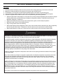
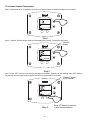
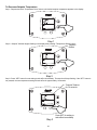
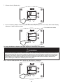
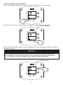
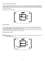
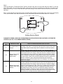
Non-Flue Damper Models (Figure 5)
Flue Damper Models (Figure 5)
The following notes apply to the tables accompanying Figures 1 - 5.
1. All models with flue dampers and/or above 400,000 BTU per hour input employ a “spark to pilot” (IID) ignition system
and requires 120 volt AC electric supply.
2. Model number may have a suffix “N” for natural gas or “X” for liquefied petroleum (LP) gases. Some models may
have “A” as a suffix for ASME. Check the rating plate on front of the water heater for model number verification.
Model Description
A
(in.)
B
(in.)
C
(in.)
D
(in.)
E
(in.)
Capacity
(GAL)
Input
(BTU/hr)
75
160,000
(155,000
LP)
70.13 67.13 65.00 54.50 6
Model Description
A
(cm)
B
(cm)
C
(cm)
D
(cm)
E
(cm)
Capacity
(Liters)
Input
(kW/hr)
283.9
46.9
(45.4 LP)
178 171 165 138 15.2
Model Description
A
(in.)
B
(in.)
C
(in.)
D
(in.)
E
(in.)
Capacity
(GAL)
Input
(BTU/hr)
75 125,000 72.25 67.13 65.00 54.50 5
75
160,000
(155,000
LP)
72.25 67.13 65.00 54.50 6
Model Description
A
(cm)
B
(cm)
C
(cm)
D
(cm)
E
(cm)
Capacity
(Liters)
Input
(kW/hr)
283.9 36.6 183 171 165 138 12.7
283.9
46.9
(45.4 LP)
184 171 165 138 15.2
Figure 5

8
SECTION III: GENERAL INFORMATION
FEATURES
1. Porcelain enamel lined tank provides corrosion protection with a tough glass lining on the interior of the tank.
2. Magnesium anodes provide an extra measure of protection and extends tank life.
3. Flue Damper on 24 volt ignition models reduces standby losses on the burner off cycle saving fuel.
4. Hand Hole Cleanout allows inspection of tank interior and allows the removal of lime and sediment deposits.
5. Honeywell Integrated Water Heater Control on 24 volt models having the following features:
Attractive digital water heater display on control panel for precisely setting and displaying the temperature setpoint.
Pressing temperature up and down buttons changes the temperature setpoint. Temperature format may be
displayed in degrees F or degrees C.
Single control board with plug in wiring controls temperature, ignition, and flue damper operation.
Reduced number of parts for servicing and wiring.
Plug in wiring reduces chance of miswiring.
Water heater display will show diagnostic codes in the event the water heater needs servicing. Aids in diagnosing
and servicing the water heater. Temperature of the tank sensors can be monitored in the Service Mode.
Water heater display can show up to 10 previous error codes to further aid in servicing the water heater.
Keep clear of combination temperature and pressure relief valve discharge line outlet. The discharge may be
hot enough to cause scald injury. The water is under pressure and may splash.
For protection against excessive temperatures and pressure, install temperature and pressure protective equipment
required by local codes, but not less than a combination temperature and pressure relief valve certified by a
nationally recognized testing laboratory that maintains periodic inspection of production of listed equipment or
materials as meeting the requirements of the Standard for Relief Valves and Automatic Gas Shutoff Devices for Hot
Water Supply Systems, ANS Z21.22 and the Standard CAN1-4.4 Temperature, Pressure, Temperature and
Pressure Relief Valves and Vacuum Relief Valves. The combination temperature and pressure relief valve must be
marked with a maximum set pressure not to exceed the maximum working pressure of the water heater. The
combination temperature and pressure relief valve must also have an hourly rated temperature steam BTU
discharge capacity not less than the hourly rating of the water heater.
Install the combination temperature and pressure relief valve into the opening provided and marked for this purpose
on the water heater.
Note: Some models may already be equipped or supplied with a combination temperature and pressure relief valve.
Verify that the combination temperature and pressure relief valve complies with local codes. If the combination
temperature and pressure relief valve does not comply with local codes, replace it with one that does. Follow the
installation instructions above on this page.
Install a discharge line so that water discharged from the combination temperature and pressure relief valve will exit
within six (6) inches (15.2 cm) above, or any distance below the structural floor and cannot contact any live electrical
part. The discharge line is to be installed to allow for complete drainage of both the combination temperature and
pressure relief valve and the discharge line. The discharge opening must not be subjected to blockage or freezing.
DO NOT thread, plug or cap the discharge line. It is recommended that a minimum clearance of four (4) inches
(10.2 cm) be provided on the side of the water heater for servicing and maintenance of the combination temperature
and pressure relief valve.
Do not place a valve between the combination temperature and pressure relief valve and the tank.
WARNING

9
DISHWASHING MACHINE REQUIREMENTS
All dishwashing machines meeting the National Sanitation Foundation requirements are designed to operate with water
flow pressures between 15 and 25 pounds per square inch. Flow pressures above 25 pounds per square inch, or below
15 pounds per square inch, will result in improperly sanitized dishes.
The National Sanitation Foundation also recommends circulation of 180°F water. Where this is done, the circulation
should be very gentle so that it does not cause any unnecessary turbulence inside the water heater. The circulation
should be just enough to provide 180°F water at the point of take-off to the dishwashing machine. Adjust flow by means of
the valve in the circulation line.
A sacrificial anode is used to extend tank life. The removal of this anode, except for inspection and/or replacement, will
nullify the warranty. In areas where water is unusually active, an odor may occur at the hot water faucet due to a reaction
between the sacrificial anode and the impurities in the water. If this should happen, an alternative anode may be
purchased from the supplier that installed this water heater. This will minimize the odor while protecting the tank.
Additionally, the water heater should be flushed with appropriate dissolvers to eliminate any bacteria.
WARNING
This product contains one or more chemicals known to the State of
California to cause cancer, birth defects, or reproductive harm.

10
SECTION IV: INSTALLATION INSTRUCTIONS
INSTALLATION OF THIS WATER HEATER REQUIRES ABILITY EQUIVALENT TO THAT OF A LICENSED
TRADESMAN IN THE FIELD INVOLVED. PLUMBING, AIR SUPPLY, VENTING, GAS SUPPLY AND
ELECTRICAL WORK ARE REQUIRED.
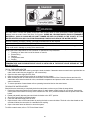
DO NOT ATTEMPT TO LIGHT ANY GAS APPLIANCE IF YOU ARE NOT CERTAIN OF THE FOLLOWING:
Liquefied petroleum gases/propane gas and natural gas have an odorant added by the gas supplier that
aids in detection of the gas.
Most people recognize this odor as a “sulfur” or “rotten egg” smell.
Other conditions, such as “odorant fade” can cause the odorant to diminish in intensity, or “fade”, and not be
as readily detectable.
If you have a diminished sense of smell, or are in any way unsure of the presence of gas, immediately
contact your gas supplier from a telephone in another building.
Gas detectors are available. Contact your gas supplier or plumbing professional for more information.
Liquefied petroleum gases/propane gas is heavier than air and will remain at floor level if there is a leak.
Basements, crawl spaces, closets and areas below ground level will serve as pockets for accumulation of leaking
gas. Before lighting, smell all around the appliance area for gas. Be sure to smell next to the floor.
IF YOU SMELL GAS:
Do not try to light any appliance.
Do not touch any electric switch; do not use any telephone in your building.
Immediately call your gas supplier from a telephone in another building. Follow the gas supplier’s
instructions.
If you cannot reach your gas supplier, call the fire department.
DO NOT OPERATE THE APPLIANCE UNTIL THE LEAKAGE IS CORRECTED!
This water heater must be located in an area where leakage of the tank, water line connections, or the combination
temperature and pressure relief valve will not result in damage to the area adjacent to the water heater or to lower
floors of the structure. When such locations cannot be avoided, a suitable drain pan must be installed under the
water heater. The drain pan depth must be suitable for draining and collecting water, and have a minimum length
and width of at least four (4) inches (10.0 cm) measured from the jacket of the water heater. The drain pan, as
described above, can be purchased from your plumbing professional. The drain pan must be piped to an adequate
drain. The piping must be at least ¾ inch (2.0 cm) in diameter and pitched for proper drainage.
Water heaters are heat producing appliances. To avoid damage or injury there must be no materials stored against
the water heater and proper care must be taken to avoid unnecessary contact (especially by children) with the water
heater components. UNDER NO CIRCUMSTANCES SHALL FLAMMABLE MATERIALS, SUCH AS GASOLINE
OR PAINT THINNER BE USED OR STORED IN THE VICINITY OF THIS WATER HEATER, VENT-AIR INTAKE
SYSTEM OR IN ANY LOCATION FROM WHICH FUMES COULD REACH THE WATER HEATER OR VENT-AIR
INTAKE SYSTEM.
Failure to adhere to these installation and operating instructions may create a hazard to life and property and will
nullify the warranty.
WARNING

11
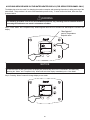
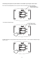
Minimum Clearances
The location of this water heater is of the utmost importance. Before installing this water heater, you should read the
Installation section of these instructions. After reading these Installation and Operating Instructions, select a location for
the water heater where the floor is level and is easily accessible to water lines, gas supply (type identified on the rating
plate), an adequate open drain, and a chimney or exhaust gas vent. DO NOT locate the water heater where water
lines could be subjected to freezing temperatures. Make sure the cold water pipes are not located directly above
the gas control box or any other electrical control so that condensate during humid weather does not drip on the
controls.
This installation must allow access to the front of the water heater and adequate clearance must be provided for servicing
and operating this water heater. The water heater may be installed on either a combustible or non-combustible floor. If the
water heater is to be installed directly on carpeting, it must be installed on top of a metal or wood panel (or equivalent)
extending beyond the full width and depth of the appliance by at least three (3) inches (7.6 cm) in any direction or, if the
appliance is to be installed in an alcove or closet, the entire floor must be covered by the panel. The minimum clearances
to combustibles for this water heater are given on the following pages. A minimum of 24 inches front clearance must be
provided for inspection and servicing. Adequate clearances must be provided for easy access to controls by service
personnel to enable proper cleaning, servicing, and operation of the water heater. Under no circumstances is the front of
the water heater to be placed in a position where the burner tray assembly cannot slide out for removal when servicing.
This water heater MUST be installed indoors out of the wind and weather.
Note: For California installation this water heater must be braced, anchored, or strapped to avoid falling or
moving during an earthquake. See instructions for correct installation procedures. Instructions may be obtained
from DSA Headquarters Office, 1102 Q Street, Suite 5100, Sacramento, California 95811.
Water heater corrosion and component failure can be caused by the heating and breakdown of airborne chemical vapors.
Examples of some typical compounds that are potentially corrosive are: spray can propellants, cleaning solvents,
refrigerator and air conditioning refrigerants, swimming pool chemicals, calcium and sodium chloride, waxes and process
chemicals. These materials are corrosive at very low concentration levels with little or no odor to reveal their presence.
DAMAGE TO THE WATER HEATER CAUSED BY EXPOSURE TO CORROSIVE VAPORS IS NOT COVERED
BY THE WARRANTY. DO NOT OPERATE THE WATER HEATER IF EXPOSURE HAS OR WILL OCCUR. DO
NOT STORE ANY POTENTIALLY CORROSIVE COMPOUNDS IN THE VICINITY OF THE WATER HEATER.
NOTICE
The National Fuel Gas Code (ANSI Z233.1- latest edition) or in Canada The Natural Gas or Propane
Installation Code CAN/CGA (B149.1, B149.2- latest edition), expressly prohibits the following:
a. Installation of a water heater in a bathroom, bedroom, or any occupied room normally kept closed.
b. Installation of a water heater in a garage, unless the unit is installed so that the burner and ignition devices are
at least eighteen (18) inches (45.8 cm) above floor level and protected to avoid damage by a moving vehicle.
If the buildings cold water supply has a back-flow preventer, check valve or water meter with check valve, provisions
for thermal expansion of water in the hot water system must be provided.
CAUTION
IF COMBUSTIBLE FLOORING IS USED, A THERMAL BREAK LEG KIT MUST BE INSTALLED BEFORE
SETTING WATER HEATER IN PLACE. THE APPROPRIATE LEG KIT HAS BEEN INCLUDED WITH THIS WATER
HEATER.
WARNING

12
UNPACKING
INSPECT SHIPMENT carefully for any signs of damage.
1. All equipment is carefully manufactured, inspected and packed.
2. Any claims for damage or shortage in shipment must be filed immediately with the manufacturer noted on the
rating plate label.
LOCATE WATER HEATER in front of final position before removing crate.
1. LOCATE so that venting connections will be short and direct.
2. THIS WATER HEATER IS SUITABLE FOR INSTALLATION ON COMBUSTIBLE FLOOR. The thermal break leg
kit supplied with the water heater must be used.
3. Proper venting practices must be considered when selecting a location for this water heater. For exact venting
specifications, please consult the Venting section of these Installation and Operating Instructions.
4. It is recommended that a minimum clearance of four (4) inches (10.2 cm) be provided on the side of the water
heater for servicing and maintenance of the combination temperature and pressure relief valve.
5. Increase distances to provide clearance for servicing.
Input
Front, sides
and Rear “A”
Less than or equal to 300,000 BTUH 2 in. (5.1 CM)
Greater than 300,000 BTUH 6 in (15.2 CM)

13
REMOVE CRATE
1. Remove all banding and pry off crate sides carefully so as not to damage the water heater.
2. Carefully roll/lift the water heater from the crate base.
MOVE WATER HEATER TO PERMANENT POSITION by sliding or walking. Place drain pan underneath water heater
INSTALL TEMPERATURE AND PRESSURE RELIEF VALVE (if not already installed).
This water heater must be located in an area where the general public does not have access to set temperatures.
AIR REQUIREMENTS
1. Do not obstruct the flow of ventilating air.
2. For safe operation, adequate air is needed for combustion and ventilation. Sooting may result in serious damage
to the water heater and risk of fire or explosion. It can also create a risk of asphyxiation. Such a condition often
will result in a yellow, luminous burner flame, causing carboning or sooting of the combustion chamber, burner
and flue tubes.
CONFINED SPACES
If the water heater is installed in a confined space (volume is less than 50 ft.
3
/1000 BTU (15 m
3
/0.29 kW) per hour of the
total input rating of all gas appliances in that space), air must be supplied through two permanent openings. One opening
must be within 12 inches (30.5 cm) from the top of the enclosure and one within 12 inches (30.5 cm) of the bottom. The
openings must be protected by metal louvers or 1/4” (6.4 mm) min. mesh metal screen. The size of the openings are as
follows:
1. If the openings communicate directly with an additional room(s) of sufficient volume, each opening must have a
minimum free area opening of 1 in.
2
/1000 BTU (2.54cm
2
/0.29kW) per hour of the total input rating of all gas
appliances in the confined space, but not less than 100 in.
2
(254 cm
2
).
2. If the openings communicate with the outdoors through horizontal ducts, each opening must have a minimum free
area of 1 in.
2
/2000 BTU (2.54cm
2
/0.59kW) per hour of the total rating of all gas appliances in the enclosure.
3. If the openings communicate directly with the outdoors or through vertical ducts with the outdoors, each opening must
have a minimum free area of 1 in.
2
/4000 BTU (2.54cm
2
/1.18kW) per hour of the total rating of all gas appliances in
the enclosure.
IMPORTANT-The flow of combustion and ventilating air must not be obstructed.
MECHANICAL EXHAUSTING OF ROOM AIR - Where an exhaust fan is installed in the same room with this
water heater and combustion air is drawn from inside the room, sufficient openings for air must be provided in the
walls. UNDERSIZED OPENINGS WILL CAUSE AIR TO BE DRAWN INTO THE ROOM THROUGH THE WATER
HEATER’S VENTING SYSTEM, CAUSING POOR COMBUSTION THAT MAY BE HAZARDOUS TO LIFE.
SOOTING MAY RESULT IN SERIOUS DAMAGE TO THE WATER HEATER AND RISK OF FIRE OR EXPLOSION,
WHICH CAN ALSO CREATE A RISK OF ASPHYXIATION. Refer to local codes and /or National Fuel Gas Code
(ANSI Z223.1-Latest Edition), or in Canada CAN/CGA B149.1 Natural Gas Installation Code (Latest Edition) or
CAN/CGA B149.2 Propane Installation Code (Latest Edition) for proper air opening sizing.
WARNING
The draft diverter relief opening of the water heater and combustion air inlet must be in the same atmospheric
pressure zone. Large exhaust fans in kitchens and other locations can lower the air pressure inside an enclosure
and interfere with the proper operation and venting of the water heater. In these cases, the water heater should be
installed in a separate room with the combustion and ventilation air supplied directly from outdoors as previously
described.
CAUTION

14
ALL AIR FROM INSIDE THE BUILDING: The confined space must be provided with two permanent openings
communicating directly with an additional room(s) of sufficient volume so that the combined volume of all spaces meets
the criteria for an unconfined space. The total input of all gas utilization equipment installed in the combined space must
be considered in making this determination. Each opening must have a minimum free area of 1 in.
2
/1000 BTU
(2.54cm
2
/0.29kW) per hour of the total input rating of all gas utilization equipment in the confined space, but not less than
100 square inches (254cm
2
). One opening must be within 12 inches (30.5 cm) of the top and one within 12 inches (30.5
cm) of the bottom of the enclosure.
UNCONFINED SPACES
In unconfined spaces in buildings, infiltration may be adequate to provide air for combustion, ventilation and dilution of flue
gases. However, in buildings of tight construction (for example, weather stripping, heavily insulated, caulked, vapor
barrier, etc.), additional air may need to be provided using the methods described above under CONFINED SPACES: All
Air From Outdoors or SPECIALLY ENGINEERED INSTALLATIONS.
SPECIALLY ENGINEERED INSTALLATIONS
The requirements noted under CONFINED SPACES above must not necessarily govern when special engineering,
approved by the authority having jurisdiction, provides an adequate supply of air for combustion, ventilation, and dilution
of flue gases.

15
SECTION V: VENTING
This water heater has been shipped with a draft diverter for which it was designed with reference to the horizontal and
vertical planes, its certified category I, per latest ANSI Z 21.10.3-2015.CSA 4.3-2015 revision. Refer to the latest edition
of the National Fuel Gas Code (ANSI Z223.1-latest edition), or in Canada, the Natural Gas and Propane installation Code
(B149.1-00 latest edition). If removed, the draft diverter must be replaced in the same position and secured to the jacket
top by the screws with which it was installed.
This water heater must be connected to a lined masonry chimney or venting system approved by local codes or
ordinances. The vent connector used to attach the draft diverter outlet to the chimney or approved vent must be of the
same diameter as the draft diverter outlet or larger. For proper venting in certain installations, a larger vent connector may
be needed. Consult venting tables in ANSI standard (Z223.1- latest edition), National Fuel Gas Code and CAN/CGA
(B149.1 or B149.2-latest editions) Natural Gas and Propane Installation Code, or local code officials for proper application
for your area.
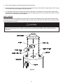
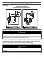
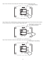
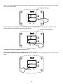
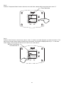
FLUE DAMPER
Refer to Figure 6 and follow these instructions:
1. Remove the damper from the accompanying box shipped within the crate.
2. Locate the collector outlet on top of the water heater. Place the damper over the collector outlet and rotate as
necessary to a position in which the damper wiring plug can be fully engaged with the connector on the side of the
water heater.
Do not turn on electrical power to water heater until flue damper is installed and water heater is filled with water.
CAUTION
The venting system must be installed properly following all local codes or in the absence of local codes, the latest
edition of the National Fuel Gas Code (ANSI Z223.1- latest edition), or in Canada, The Natural Gas and Propane
Installation Code (B149.1-00 latest edition). Failure to properly install the venting system could result in property
damage, personal injury, or death.
Carefully inspect the venting system of a replacement water heater installation before connecting to the venting
system. All joints in the vent connector must be securely fastened with screws and fit tightly together. Inspect the
venting system for signs of deterioration (rust and perforation) and replace any sections that are not in good
condition.
The chimney must be lined and in good condition. Check to make sure the venting system is properly sized for the
water heater. If the venting system was previously sized for another gas appliance that has been removed, the
venting system may now be too large. Refer to the latest edition of the National Fuel Gas Code (ANSI Z223.1-latest
edition), or in Canada, the Natural Gas and Propane Installation Code (B149.1-00 latest edition) for the correct
sizing of venting systems and common venting with another gas appliance. Do not vent this water heater into the
venting system of another gas appliance designed to vent under positive pressure.
The water heater should be installed as close as practical to the venting system to minimize the vent connector
length required. Refer to local codes for the distance limitations on vent connector lengths. At the completion of the
water heater installation, the burner and venting system must be checked for proper operation with all other
commonly vented appliances in operation. Check for spillage of flue products around the outside relief opening of
the drafthood after several minutes of operation. The flame from a match should be drawn into the drafthood. Do not
use the water heater or connected equipment if spillage is detected until the problem is corrected. Refer to the latest
edition of the National Fuel Gas Code, or in Canada, the Natural Gas and Propane Installation Code for complete
details on the “Procedure to Be Followed to Place Equipment in Operation”.
WARNING

16
3. Secure the flue damper to the jacket top with sheet metal screws.
4. Connect the damper wiring plug to the damper wire harness connector on the side of the water heater. Note: The plug
and connector can only be engaged one way (polarized).
5. The Lighting and Operating instructions are outlined in this manual. The damper must be in the open position when
the water heater main burner is operating (the arrow on the damper plate is in the “up” position when open. Be certain
the arrow is in a visible position when installed).
DRAFT DIVERTER
This water heater has been shipped with a draft diverter for which it was designed. Remove the bag containing the legs
and instructions from the draft diverter. Attach the legs to the draft diverter and attach the draft diverter to the water heater
per the instructions in the bag.
Figure 6
Modification to the flue damper or the draft diverter may result in personal injury, property damage or death. The flue
damper and draft diverter are to be placed in position and operate exactly as stated in these instructions without
modification.
CAUTION

17
SECTION VI: WATER CONNECTIONS
NOTE: BEFORE PROCEEDING WITH THE INSTALLATION, CLOSE THE MAIN WATER SUPPLY VALVE.
After shutting off the main water supply, open a faucet to relieve the water line pressure to prevent any water from leaking
out of the pipes while making the water connections to the water heater. After the pressure has been relieved, close the
faucet. The COLD water inlet and HOT water outlet are identified on the top and front of the water heater. Make sure the
diptube is in place before making the cold water connection. Make the proper plumbing connections between the water
heater and the plumbing system to the house. Install a shut-off valve in the cold water supply line.
After installation of the water lines, open the main water supply valve and fill the water heater. While the water heater is
filling, open several hot water faucets to allow air to escape from the water system. When a steady stream of water flows
through the faucets, close them and check all water connections for possible leaks. NEVER OPERATE THE WATER
HEATER WITHOUT FIRST BEING CERTAIN IT IS FILLED WITH WATER.
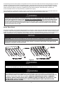
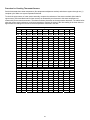
APPROXIMATE TIME/TEMPERATURE RELATIONSHIPS IN SCALDS
120°F (49°C) More than 5 minutes
125°F (52°C) 1½ to 2 minutes
130°F (54°C) About 30 seconds
135°F (57°C) About 10 seconds
140°F (60°C) Less than 5 seconds
145°F (63°C) Less than 3 seconds
150°F (66°C) About 1½ seconds
155°F (68°C) About 1 second
If sweat fittings are to be used, DO NOT apply heat to the nipples on top or side of the water heater. Sweat the
tubing to the adapter before fitting the adapter to the water heater connections. It is imperative that heat is not
applied to the nipples containing a plastic liner.
CAUTION
FAILURE TO INSTALL AND MAINTAIN A NEW, LISTED TEMPERATURE AND PRESSURE RELIEF VALVE
WILL RELEASE THE MANUFACTURER FROM ANY CLAIM WHICH MIGHT RESULT FROM EXCESSIVE
TEMPERATURE AND PRESSURES
.
WARNING
If this water heater is installed in a closed water supply system, such as the one having a back-flow preventer in the
cold water supply, provisions must be made to control thermal expansion. DO NOT operate this water heater in a
closed system without provisions for controlling thermal expansion. Warranties do not cover damages from thermal
expansions such as pressure bulges and/or deformities. Your water supplier or local plumbing inspector should be
contacted on how to control this situation.
NOTICE

18
This water heater can deliver scalding temperature
water at any faucet in the system. Be careful
whenever using hot water to avoid scalding injury.
Certain appliances such as dishwashers and
automatic clothes washers may require increased
temperature water. By setting the thermostat on this
water heater to obtain the increased temperature
water required by these appliances, you may create
the potential for scald injury. To protect against injury,
you should install an ASSE approved mixing valve in
the water system. This valve will reduce point of
discharge temperature by mixing cold and hot water in
branch supply lines. Such valves are available from
the manufacturer of this water heater or a local
plumbing supplier. Please consult with a plumbing professional. For information regarding space heating water
connections and plumbing arrangements, refer to the section at the end of this manual.
Keep clear of combination temperature and pressure relief valve discharge line outlet. The discharge may be
hot enough to cause scald injury. The water is under pressure and may splash.
For protection against excessive temperatures and pressure, install temperature and pressure protective equipment
required by local codes, but not less than a combination temperature and pressure relief valve certified by a
nationally recognized testing laboratory that maintains periodic inspection of production of listed equipment or
materials as meeting the requirements of the Standard for Relief Valves and Automatic Gas Shutoff Devices for Hot
Water Supply Systems, ANS Z21.22 and the Standard CAN1-4.4 Temperature, Pressure, Temperature and
Pressure Relief Valves and Vacuum Relief Valves. The combination temperature and pressure relief valve must be
marked with a maximum set pressure not to exceed the maximum working pressure of the water heater. The
combination temperature and pressure relief valve must also have an hourly rated temperature steam BTU
discharge capacity not less than the hourly rating of the water heater.
Install the combination temperature and pressure relief valve into the opening provided and marked for this purpose
on the water heater.
Note: Some models may already be equipped or supplied with a combination temperature and pressure relief valve.
Verify that the combination temperature and pressure relief valve complies with local codes. If the combination
temperature and pressure relief valve does not comply with local codes, replace it with one that does. Follow the
installation instructions above on this page.
Install a discharge line so that water discharged from the combination temperature and pressure relief valve will exit
within six (6) inches (15.2 cm) above, or any distance below the structural floor and cannot contact any live electrical
part. The discharge line is to be installed to allow for complete drainage of both the combination temperature and
pressure relief valve and the discharge line. The discharge opening must not be subjected to blockage or freezing.
DO NOT thread, plug or cap the discharge line. It is recommended that a minimum clearance of four (4) inches
(10.2 cm) be provided on the side of the water heater for servicing and maintenance of the combination temperature
and pressure relief valve.
Do not place a valve between the combination temperature and pressure relief valve and the tank.
Hydrogen gas can be produced in an operating water heater that has not had water drawn from the tank for
a long period of time (generally two weeks or more). Hydrogen gas is extremely flammable. To prevent the
possibility of injury under these conditions, we recommend the hot water faucet to be open for several
minutes at the kitchen sink before you use any electrical appliance which is connected to the hot water
system. If hydrogen is present, there will be an unusual sound such as air escaping through the pipes as
hot water begins to flow. Do not smoke or have open flame near the faucet at the time it is open.
WARNING

19
SECTION VII: GAS CONNECTIONS
The gas supply lines must meet all requirements of the National Fuel Gas Code (ANSI Z223.1-Latest Edition), or in
Canada CAN/CGA B149.1 Natural Gas Installation Code (Latest Edition) or CAN/CGA B149.2 Propane Installation Code
(Latest Edition).
The minimum permissible gas supply pressure for the purpose of input adjustment is one (1.0) inch (0.25 kPa) water
column above the operating manifold pressure. See the rating plate and gas valve for the manifold pressure and gas type.
The maximum permissible gas supply pressure is fourteen (14.0) inches (3.5 kPa) water column for natural gas and
liquefied petroleum gases/propane gas.
1. Connect this water heater only to the type of gas (Natural or Propane gas) as shown on the rating plate. Use clean
black iron pipe or equivalent material approved by local codes and ordinances. (Dirt and scale from the pipe can enter
the gas valve and cause it to malfunction). The inlet gas line must have a minimum length of three (3) inches (7.6 cm)
drip leg (sediment trap) installed as close to the water heater’s gas valve as possible. A ground joint union must be
installed as close to the water heater as possible in the gas supply line feeding the water heater to permit servicing of
the water heater. Compounds used on the threaded joints of the gas piping must be resistant to the action of liquefied
petroleum gases/propane gas. DO NOT apply pipe dope to the gas valve inlet and make certain that no pipe dope
has become lodged in the inlet screen of the gas valve. Extreme care must be taken to ensure no pipe dope enters
the gas valve. Avoid excessive torque when tightening the gas supply line to the gas valve. Excessive torque may
result in cracking of the gas valve housing and could create a gas leak. The suggested maximum torque is 31.5 ft.
lbs. (4.4 kg-m).
2. This water heater and its gas connection must be leak tested before placing the water heater in operation. Check for
gas leaks with a soap and water solution and a brush or a commercial leak detector fluid. NEVER USE A MATCH OR
OPEN FLAME FOR TESTING!
3. While checking for leaks care must be taken to prevent solution from contacting the electrical connections at the
control. If electrical connections at the control become wet, they must be thoroughly dried before attempting to
operate the water heater.
The manufacturer of this water heater will not be liable for any damage or injury caused as a result of a cracked gas
inlet as a result of excessive torque.
WARNING
The water heater and individual shutoff valve must be disconnected from the gas supply piping system during any
pressure testing of the system at test pressures in excess of 1/2 psi (3.5 kPa). The water heater must be isolated
from the gas supply piping system by closing its manual shutoff valve during any pressure testing of the gas supply
system at test pressures equal to or less than 1/2 psi (3.5 kPa). The supply line must be capped when not
connected to the water heater.
CAUTION

20
WARNING
Water heaters are heat-producing appliances. To avoid damage or injury there must be no materials stored against
the water heater or direct vent system, and proper care must be taken to avoid unnecessary contact (especially by
children) with the water heater and direct vent system. UNDER NO CIRCUMSTANCES SHOULD FLAMMABLE
MATERIALS, SUCH AS GASOLINE OR PAINT THINNER BE USED OR STORED IN THE VICINITY OF THIS
WATER HEATER OR IN ANY LOCATION FROM WHICH FUMES COULD REACH THE WATER HEATER.
Installation or service of this water heater requires ability equivalent to that of a licensed tradesman in the field
involved. Plumbing, air supply, venting, gas supply and electrical work are required.
Light the unit in accordance with the operating instructions label attached to the water heater.
Under no circumstances should the input rate exceed the input rate shown on the water heater rating plate. Over
firing could result in damage or sooting of the water heater.
If the unit is exposed to the following, do not operate water heater until all corrective steps have been made by a
factory authorized independent service contractor or qualified service professional.
1. Flooding to or above the level of the burner or controls
2. External firing
3. Damage
4. Firing without water
5. Sooting
NEVER OPERATE THE WATER HEATER WITHOUT FIRST BEING CERTAIN IT IS FILLED WITH WATER AND A
TEMPERATURE AND PRESSURE RELIEF VALVE IS INSTALLED IN THE RELIEF VALVE OPENING OF THE
WATER HEATER.
TO FILL THE WATER HEATER
1. Close the water heater drain valve by turning the knob clockwise. If alternative water connections are provided but not
used, make certain they are plugged (i.e. rear connections).
2. Open the cold water supply shut-off valve.
3. Open several hot water faucets to allow air to escape from the system.
4. When a steady stream of water flows from the faucets, the water heater is filled. Close the faucets and check for
water leaks at the water heater drain valve, combination temperature and pressure relief valve and the hot and cold
water connections.
5. To restore operation of water heater refer to operating instruction label on the water heater.
TO DRAIN THE WATER HEATER
Should it become necessary to completely drain the water heater, make sure you follow the steps below:
1. Reduce the thermostat setpoint to the lowest setting. On water heater models having 24 volt controls, depress the
control panel rocker switch on the top of the control box to the “OFF” position and disconnect the power to the water
heater.
2. Rotate and partially depress gas control knob clockwise to the “OFF” position.
3. Shut off the gas supply to the water heater.
4. Close the cold water supply shut-off valve.
5. Open the drain valve on the water heater by turning the knob counter-clockwise. The drain valve has threads on the
end that will allow the connection of a standard hose coupling.
6. Open a hot water faucet to allow air to enter the system.
To refill the water heater, refer to “To Fill the Water Heater.”
Page is loading ...
Page is loading ...
Page is loading ...
Page is loading ...
Page is loading ...
Page is loading ...
Page is loading ...
Page is loading ...
Page is loading ...
Page is loading ...
Page is loading ...
Page is loading ...
Page is loading ...
Page is loading ...
Page is loading ...
Page is loading ...
Page is loading ...
Page is loading ...
Page is loading ...
Page is loading ...
Page is loading ...
Page is loading ...
Page is loading ...
Page is loading ...
Page is loading ...
Page is loading ...
Page is loading ...
Page is loading ...
Page is loading ...
Page is loading ...
Page is loading ...
Page is loading ...
Page is loading ...
Page is loading ...
Page is loading ...
Page is loading ...
-
 1
1
-
 2
2
-
 3
3
-
 4
4
-
 5
5
-
 6
6
-
 7
7
-
 8
8
-
 9
9
-
 10
10
-
 11
11
-
 12
12
-
 13
13
-
 14
14
-
 15
15
-
 16
16
-
 17
17
-
 18
18
-
 19
19
-
 20
20
-
 21
21
-
 22
22
-
 23
23
-
 24
24
-
 25
25
-
 26
26
-
 27
27
-
 28
28
-
 29
29
-
 30
30
-
 31
31
-
 32
32
-
 33
33
-
 34
34
-
 35
35
-
 36
36
-
 37
37
-
 38
38
-
 39
39
-
 40
40
-
 41
41
-
 42
42
-
 43
43
-
 44
44
-
 45
45
-
 46
46
-
 47
47
-
 48
48
-
 49
49
-
 50
50
-
 51
51
-
 52
52
-
 53
53
-
 54
54
-
 55
55
-
 56
56


Bradford White D-80T-425-3N User manual
- Category
- Water heaters & boilers
- Type
- User manual
Ask a question and I''ll find the answer in the document
Finding information in a document is now easier with AI
Related papers
-
Bradford White D65T6253XA User manual
-
Bradford White D-65T-399-3N User manual
-
Bradford White 100T-88B-3N User manual
-
-
-
-
-
-
Bradford White RG230T6N User manual
-
Bradford White UCG-100H-199-3N User guide
Other documents
-
andrews Balanced Flue Range CSC User manual
-
CMI 192-5895 Installation guide
-
 Perfect Fit TNU100-200 User guide
-
Rheem G75-125 User guide
-
Rheem GN76-200 User manual
-
Rheem GNU100-250 User manual
-
Rheem G100MF/418995 Installation guide
-
Lochinvar LBF401 User Instructions
-
American Water Heater GAS-FIRED COMMERCIAL WATER HEATER User manual
-
Atwood MPD 93755 Installation Operation & Maintenance
