Page is loading ...

September
1987
FORM:
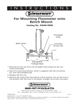
OM-880
MODEL
CV-2
CONSTANT
VOLTAGE
CONTROL
PANEL
OWNERS
MANUAL
Il~AI~]:IV..t~I~
Read
and
understand
the
entire
contents
of
this
manual,
with
special
emphasis
on
the
safety
material
throughout
the
manual,
Miller
Electric
Mfg.Co.
AMdIerGro~pLtd.Cornpnny
before
installing,
operating,
or
maintaining
this
equipment.
This
unit
and
P0.
Box
1079
these
instructions
are
for
use
only
by
persons
trained
and
experienced
in
Appleton,
WI
54912
USA
the
safe
operation
of
welding
equipment.
Do
not
allow
untrained
persons
Tel.
414-734-9821
to
install,
operate,
or
maintain
this
unit.
Contact
your
distributor
if
you
do
not
fully
understand
these
instructions.
Millerfi
Effective
With
Serial
No.
JH241534
PRINTED
IN
U.S.A.
ADDITIONAL
COPY
PRICE
85
CENTS

LIMITED
WARRANTY
.
EFFECTIVE:
OCTOBER
1,
1986
4.
.
.
..
~
This
warranty
supersedes
all
previous
MILLER
warranties
and
is
exclusive
with
no
other
guarantees
or
warranties
expressed
or
implied.
LIMITED
WARRANTY
-
Subject
to
the
terms
and
condi-
In
the
case
of
Millers
breach
of
warranty
or
any
other
duty
tions
hereof,
Miller
Electric
Mfg.
Co.;
Appleton,
Wisconsin
with
respect
to
the
quality
of
any
goods,
the
exclusive
remedies
~
warrants
to
its
Distributor/Dealer
that
all
new
and
unused
therefore
shall
be,
at
Millers
option
Ill
repair
or
(2)
replacement
~
~
Equipment
furnished
by
Miller
is
free
from
defect
in
workman-
or,
where
authorized
in
writing
by
Miller
in
appropriate
cases,
(3)
(~(~
ship
and
material
as
of
the
time
and
place
of
delivery
by
Miller.
the
reasonable
cost
of
repair
or
replacement
at
art
authorized
-/
No
warranty
is
made
by
Miller
with
respect
to
engines,
trade
Miller
service
station
or
(4)
payment
of
or
credit
for
the
purchase
~
~
accessories
or
other
items
manufactured
by
others.
Such
price
(less
reasonable
depreciation
based
upon
actual
use)
upon
~
~
engines,
trade
accessories
and
other
items
are
sold
subject
to
return
of
the
goods
at
Customers
risk
and
expense.
MILLERs
the
warranties
of
their
respective
manufacturers,
if
any
.
All
option
of
repair
or
replacement
will
be
FOB.,
Factory,
at
engines
are
warranted
by
their
manufacturer
for
one
year
from
Appleton,
Wisconsin,
or
F.O.B.,
at
a
MILLER
authorized
service
~
date
of
original
purchase,
except
Tecumseh
engines
which
facility,
therefore,
no
compensation
for
transportation
costs
of
~
have
a
two
year
warranty,
any
kind
will
be
allowed.
Upon
receipt
of
notice
of
apparent
defect
or
failure,
Miller
shall
instruct
the
claimant
on
the
warranty
Except
as
specified
below,
Millers
warranty
does
not
apply
claim
procedures
to
be
followed.
*
,
to
components
having
normal
useful
life
of
less
than
one
(1)
year,
such
as
spot
welder
tips,
relay
and
contactor
points,
MILLERMATIC
parts
that
come
in
contact
with
the
welding
ANY
EXPRESS
WARRANTY
NOT
PROVIDED
HEREIN
AND
~)
wire
including
nozzles
and
nozzle
insulators
where
failure
does
ANY
IMPLIED
WARRANTY,
GUARANTY
OR
REPRESENTA
not
result
from
defect
in
workmanship
or
material.
TION
AS
TO
PERFORMANCE,
AND
ANY
REMEDY
FOR
~1
BREACH
OF
CONTRACT
WHICH,
BUT
FOR
THIS
PROVISION,
~
Miller
shall
be
required
to
honor
warranty
claims
on
war-
MIGHT
ARISE
BY
IMPLICATION,
OPERATION
OF
LAW,
~
ranted
Equipment
in
the
event
of
failure
resulting
from
a
defect
CUSTOM
OF
TRADE
OR
COURSE
OF
DEALING,
INCLUDING
~
within
the
following
periods
from
the
date
of
delivery
of
Equip-
ANY
IMPLIED
WARRANTY
OF
MERCHANTABILITY
OR
OF
~
ment
to
the
original
user:
.
FITNESS
FOR
PARTICULAR
PURPOSE,
WITH
RESPECT
TO
~
ANY
AND
ALL
EQUIPMENT
FURNISHED
BY
MILLER
IS
EX
~
1.
Arc
welders,
power
sources,
robots,
and
components
1
year
CLUDED
AND
DISCLAIMED
BY
MILLER.
~
2.
Load
banks
1
year
3.
Original
main
power
rectifiers
3
years
4/
(labor-i
year
only)
EXCEPT
AS
EXPRESSLY
PROVIDED BY
MILLER
IN
4.
Allweldingguns,feeder/gunsandplasmatorches...
90days
WRITING,
MILLER
PRODUCTS
ARE
INTENDED
FOR
(~
4/
5.
All
other
Millermatic
Feeders
1
year
ULTIMATE
PURCHASE
BY
COMMERCIAL/INDUSTRIAL
~
~
6.
Replacement
or
repair
parts,
exclusive
of
labor
..
60
days
USERS
AND
FOR
OPERATION
BY
PERSONS
TRAINED
AND
7.
Batteries
6
months
EXPERIENCED
IN
THE USE
AND
MAINTENANCE
OF
WELDING
EQUIPMENT
AND
NOT
FOR
CONSUMERS
OR
~)/)
provided
that
Miller
is
notified
in
writing
within
thirty
(30)
days
CONSUMER
USE.
MILLERS
WARRANTIES
DO
NOT
EXTEND
k~
r~
of
the
date
of
such
failure.
TO,
AND
NO
RESELLER
IS
AUTHORIZED
TO
EXTEND
As
a
matter
of
general
policy
only,
Miller
may
honor
claims
MILLERS
WARRANTIES
TO,
ANY
CONSUMER.
submitted
by
the
original
user
within
the
foregoing
periods.
~
J~
~,
J~
~,
,f~
~
,,~
,
~
~%
~
j~
~.
~
~,
j1.
~
~,
~
TABLE
OF
CONTENTS
Section
No.
Page
No.
SECTION
4
-
SEQUENCE
OF
OPERATION
SECTION
1
-
INTRODUCTION
4
-
1.
Gas
Metai
Arc
(GMAWI.And
Fiux
Cored
Arc
Weiding
(FCAW)
17
4
-
2.
Shielded
Metai
Arc
Welding
(SMAWI
18
1
-
1.
Voit-Ampere
Curves
2
4
-
3.
Gas
Tungsten
Arc
Weiding
(GTAW)
18
1
-
2.
Generai
information
And
Safety
2
4
-
4.
Shutting
Down
18
1
-
3.
Receiving-Handhng
2
1
-
4.
Description
3
SECTION
5
-
MAINTENANCE
Et
TROUBLESHOOTING
SECTION
2
-
INSTALLATION
5
-
1.
Periodic
Cleaning
And
inspection
19
5
-
2.
Resetting
Circuit
Breakers
19
2
-
1.
CV-2
instaiiatuon
3
5
-
3.
Circuit
Board
PC3
Or
PC4
Repiacement
Procedure
19
2
-
2.
5-Socket
Remote
Controi
Receptacie
8
5
-
4.
Preparing
Tungsten
Eiectrodes
20
2
-
3.
14-Socket
Remote
Controi
Receptacle
9
5
-
5.
Troubieshooting
20
SECTION
3
-
OPERATOR
CONTROLS
3
-
1.
Constant
Voitage
ICV)/Constant
Current
(CC)
Switch
15
3
-2.
Current
Controi
Switch
15
3
-3.
ContactorControi
Switch
16
3
-4.
AC/DC
Seiector
Switch
16
3
-
5.
Circuit
Breaker
For
Controi
Circuitry
16

SECTION
1
-
INTRODUCTION
Model
Rated
Output
At
100%
Duty
Cycle*
DC
Load
Voltage
Range
In
CV
Mode
AC
Open-
Voltage
Range
In
CC
Mode*
AC
Amperage
Range
(n
CC
Mode*
Max.
Open-Circuit
Volts*
Weight
Net
Ship
DC
CV
Mode
AC
CC
Mode
B3IG
DIESEL
200
Amperes
At
28
Volts
10-35
40-70
45-325
Amperes
40
:
70
42
lbs.
(19
kg)
47
lbs.
(21
kg)
-
BIG
DIESEL
And
BIG4O
300
Amperes
At
32
Volts
t~-~~
Amperes
B5IG
DIESEL
300
Amperes
At 32
Volts
50-495
Amperes
*See
Owners
Manual
For
DC
Specifications
In
CC
Mode
30
0
>
C.)
20
300 350
400
0
B-ill
680
400
500
600
B-ill
678
Figure
1
-
2.
DC
Volt-Ampere
Curves
(CV
Mode)
OM-880
Page
1
50
40
Figure
1
-
1.
Specifications
50
40
30
0
>
20
10
10
50
100 150
200
250
DC
AMPERES
50
100
200
300
DC
AMPERES
400
500
600
B-i
11
879
40
30
0
>
C.,
~
20
10
0
100
200
300
DC
AMPERES

30
20
10
0
100
200
300
400 500
600
AC AMPERES
B-1i13i7
Figure
1
-
3.
AC
Volt-Ampere
Curves
(Single
Phase,
CC
Mode)
1-3)
The
volt-ampere
curves
show
the
output
voltage
and
amperage
of
the
welding
generator
avai~ab~e
at
any
point
from
the
minimum
to
maximum
of
each
coarse
amperage
range.
With
the
use
of
the
volt-ampere
curves
it
is
possible
to
determine
what
the
weld
amperage
will
be
at
a
par
ticular
arc
voltage.
The
volt-ampere
curves
show
the
minimum
and
maximum
curves
of
each
coarse
amperage
range.
1
-2.
GENERAL
INFORMATION
AND
SAFETY
A.
General
Information
presented
in
this
manual
and
on
various
labels,
tags,
and
plates
on
the
lower
front
panel
pertains
to
equipment
design,
installation,
operation,
maintenance,
and
troubleshooting
which
should
be
read,
understood,
and
followed
for
the
safe
and
effec
tive
use
of
this
equipment.
The
nameplate
of
this
panel
uses
international
symbols
for
labeling
the
controls.
The
symbols
also
appear
at
the
appropriate
section
in
the
text.
B.
Safety
The
installation,
operation,
maintenance,
and
troubleshooting
of
arc
welding
equipment
require
prac
tices
and
procedures
which
ensure
personal
safety
and
safety
of
others.
Therefore,
this
equipment
is
to
be
in
stalled,
operated,
and
maintained
only
by
qualified
per
sons
in
accordance
with
this
manual
and
all
applicable
codes
such
as,
but
not
limited
to,
those
listed
at
the
end
of
Section
1
-
Safety
Rules
For
Operation
Of
Arc
Welding
Power
Source
in
the
welding
power
source
Owners
Manual.
&~A~IJ
:
statements
include
installation,
operation,
and
maintenance
procedures
or
practices
which
if
not
carefully
followed
could
result
in
serious
personal
injury
or
loss
of
life.
1~itU1lIs1~I
statements
include
installation,
operation,
and
maintenance
procedures
or
practices
which
if
not
carefully
followed
could
result
in
minor
personal
injury
or
damage
to
this
equipment.
A
third
signal
word,
IW~l~sflhf.i~Il
highlights
instruc
tions
which
need
special
emphasis
to
obtain the
most
efficient
operation
of
this
equipment.
1
-
3.
RECEIVING-HANDLING
-
Before
installing
this
equipment,
clean
all
packing
material
from
around
the
unit
and
carefully
inspect
for
damage
that
may
have
occurred
during
shipment.
Any
claims
for
loss
or
damage
that
may
have
occurred
in
transit
must
be
filed
by
the
purchaser
with
the
carrier.
A
copy
of
the
bill
of
lading
will
be
furnished
by
the
manufacturer
on
re
quest
if
occasion
to
file
claim
arises.
When
requesting
information
concerning
this
equip
ment,
it
is
essential
that
Model
Description
and
Serial
Number
of
the
equipment
be
supplied.
100
200
300
AC
AMPERES
400 500 600
B-i
ii
309
100
90
80
70
60
50
440
30
20
10
0
100
90
80
70
60
50
U
4
40
30
20
10
0
100
90
80
70
60
50
40
100
200
300
400
AC
AMPERES
U,
0
>
U
4
500
600
Safety
instructions
specifically
pertaining
to
this
panel
B-ni
3t3
appear
throughout
this
manual_highlighted
by
the
signal
words
ITiTI~.~hIl~IeI
and
t~UIli1i~1
which
identify
different
levels
of
hazard.
1
-
1.
VOLT-AMPERE
CURVES
(Figures
1-2
And
OM-880
Page
2

1
-
4.
DESCRIPTION
-
This
Constant
Voltage
con
trol
panel
is
designed
for
use
with
the
BIG
30
DIESEL,
BIG
40
DIESEL,
BIG
40,
and
BIG
50
DIESEL
welding
generator
models.
The
CV-2
expands
capabilities
of
the
welding
generator
to
include
constant
voltage
dc
and
single-phase
ac
weld
output
selections.
A
switch
is
provided
for
making
the
ac
selection
or
for
changing
the
dc
polarity.
In
addition,
the
5-socket
and
14-socket
Amphenol
receptacles
on
this
panel
provide
a
junction
point
with
the
unit
internal
circuitry
for
connecting
equipment
used
in
Shielded
Metal
Arc
(SMAW),
Gas
Metal
Arc
(GMAW),
Flux
Cor
ed
Arc
(FCAW),
and
Gas
Tungsten
Arc
(GTAW)
Welding
processes.
A
supplied
1
ft.
(254
mm)
adapter
cord
with
2-prong
and
3-socket
plugs
to
a
14-pin
Amphenol
plug
provides
CV-2
connection
capability
to
wire
feed
equipment
us
ing
an
interconnecting
cord
with
2-socket
and
3-prong
twistlock
plugs.
Other
adapter
cords
and
extension
cords
with
different
plug
combinations
can
be
obtained
for
connecting
various
welding
system
devices
and
con
trols
to
the
CV-2
receptacles.
SECTION
2
-
INSTALLATION
______________
If
CV-2
was
factory
installed,
proceed
directly
to
Section
2-2.
2
-
1.
CV-2
INSTALLATION
WARNING:
ELECTRIC
SHOCK
can
kill.
Do
not
touch
live
electrical
parts.
Shut
down
the
engine
and
disconnect
negative
(-)
battery
cable
from
battery
before
beginning
this
installation.
MOVING
PARTS
can
cause
serious
injury.
Keep
clear
of
moving
parts,
i.e.,
fans,
belts,
rotors,
etc.
HOT
SURFACES
can
cause
severe
burns.
Wear
protective
gloves
and
clothing
when
work
ing
near
hot
parts.
Allow
unit
to
cool
down,
if
applicable,
before
beginning
installation.
A.
Preparing
Unit
For
Installation
IWd~s];l1~.ti~I~
It
is
necessary
to
move
the
top
cover
back
approximately
1
ft.
(0.3
ml
away
from
the
front
panel
to
gain
access
to
components.
1.
Remove
all
necessary
top
cover
securing
hard
ware
and
components.
2.
Raise
both
side
doors
and
tie
together
across
the
cover.
3.
Loosen
the
clamp
securing
the
air
cleaner
hose
to
the
engine
intake
manifold
and
remove
the
hose
from
the
manifold.
4.
For
BIG
40
DIESEL,
BIG
40,
and
BIG
50
DIESEL
models:
Loosen
the
clamp
securing
the
muffler
to
the
exhaust
pipe,
and
remove
the
muffler
from
the
unit.
5.
Raise
and
slide
cover
with
side
doors
approx
imately
1
ft.
(0.3
m)
back
over
radiator.
t~U1l.1~
METAL
FILINGS
AND/OR
TOOL
CONTACT
WITH
INTERNAL
COMPONENTS
can
damage
unit.
Cover
internal
components.
Clean
unit
and
remove
internal
covering
material
be
fore
resuming
operation.
IMPORTANT
6.
Drill
out
the
pop
rivet
securing
the
key
chain
to
the
lower
front
panel.
7.
Install
and
secure
key
with
key
chain
onto
CV-2
panel
at
the
prepunched
hole
location
(see
Figure
3-1:
hardware
not
supplied).
8.
Remove
and
discard
lower
front
panel
from
unit;
retain
securing
hardware.
9.
If
applicable,
disconnect
electrode
holder
and
work
clamp
cables
from
weld
output
terminals.
B.
Transformer
And
Lower
Panel
Installation
1.
Locate
and
install
supplied
transformer
T2
onto
the
welding
generator
as
follows:
a.
For
BIG
30
DIESEL
models:
Install
T2
onto
the
right
front
portion
of
the
base
mounting
strip
at
the
prepunched
hole
locations
(see
Figure
2-1).
Secure
T2
with
the
four
sup
plied
1/4-20
x
3/4
in.
screws,
flat
washer,
lock
washers,
and
nuts.
b.
For
BIG
40
DIESEL,
BIG
40,
and
BIG
50
DIESEL
models:
Install
the
supplied
moun
ting
bracket
onto
12,
and
secure
bracket
with
the
four
supplied
1/4-20
x
3/4
in.
screws,
lock
washers,
and
flat
washer.
Mount
T2
with
bracket
onto
fuel
tank
and
reactor
Zi
support
angles
(see
Figure
2-1)
with
12
located
below
right
front
corner
of
fuel
tank.
Secure
mounting
bracket
to
sup
port
angles
with
the
three
supplied
1/4-20
x
1/2
in.
self-tapping
screws.
WAI
~.]
~I ~
I
~
To
ease
CV-2
electrical
connections,
remove
weld
output
terminal
mounting
bracket
from
left
front
upright.
Also,
before
securing
C
V-2
panel
after
installation,
check
for
clearance
between
lugs
of
preinstalled
cables
on
the
AC/DC
Selector
switch
ter
minals
and
any
we/ding
generator
components.
Reposi
tion
lugs
at
switch
terminals
as
necessary
to
prevent
contact
between
parts.
2.
Install
and
secure
the
supplied
CV-2
panel
onto
the
welding
generator
with
the
hardware
remov
ed
in
Step
8
of
Section
A.
OM-880
Page
3

BIG
30
DIESEL
Transformer
T2
Installation
BIG
40
DIESEL.
BIG
40,
And
BIG
50
DIESEL
Transformer
12
Installation
Figure
2
-
1.
Location
For
Transformer
T2
Installation
C.
Electrical
Connections
1.
Disconnect
cable
30
from
rear
of
Negative
weld
Output
terminal.
2.
Install
a
6
in.
(152
mm)
long
piece
of
supplied
in
sulated
tubing
onto
cable
30
disconnected
in
Step
1.
II1~1
~i]
~I
f
~
If
unit
is
equipped
with
dc
meters,
connect
negative
(black)
voltmeter
lead
at
the
connec
tion
point
where
cables
30
join
together.
Be
sure
that
the
voltmeter
lead
is
installed
last
on
top
of
the
two
cable
terminal
lugs.
3.
Reconnect
cable
30
to
switch
Si
cable
30
and
secure
with
a
supplied
1/4-20
x
1/2
in.
flange
screw
and
nut
(see
Figure
2-2).
Figure
2
-
2.
Selector
Switch
Si
DC
Connections
Electrode
(Negative)
Weld
Output
Terminal
Weld
Output
Terminal
Assembly
(Positive)
Weld
Output
Terminal
Bimetal
Jumper
Bar-Copper
Side
Of
Bar
Against
Terminal
Surface
TB-112
688
Transformer
T2
Transformer
~
Installed
With
Installed
Onto
Mounting
Bracket
Base
Mounting
Strip
I
See
Figur~
2-5
L
,~r
Transformer
Mounting
Bracket
Orientation
Rear
View
(Inside)
Left
Front
Upright
Of
Lower
Front
Panel
When
Viewed
From
Front
Of
Control
Panel
Cable
30
From
Cable
30
Negative
Weld
Output
Terminal
And
Black
Output
Terminal
Switch
Si
Cable
19
OM-880
Page
4

4.
Slide
the
installed
tubing
over
connection,
and
secure
with
two
supplied
nylon
cable
ties
(see
Figure
2-2).
5.
Disconnect
cable
19
from
rear
of
Positive
weld
output
terminal.
6.
Install
the
remaining
6
in.
(152
mm)
long
piece
of
insulated
tubing
onto
cable
19
disconnected
in
Step
5.
7.
Reconnect
cable
19
to
switch
Si
cable
19,
and
secure
with
a
supplied
1/4-20
x
1/2
in.
flange
screw
and
nut
(see
Figure
2-2).
8.
Slide
the
installed
tubing
over
connection,
and
secure
with
two
supplied
nylon
cable
ties
(see
Figure
2-2).
9.
Connect
cable
28
from
switch
Si
to
rear
of
Negative
weld
output
terminal
(see
Figure
2-2).
~
ELECTRIC
SHOCK
can
kill;
BIMETAL
JUMPER
BAR
CONTACT
WITH
INTER
NAL
COMPONENTS
can
cause
personal
injury
and
equipment
damage.
Do
not
touch
live
electrical
parts.
Do
not
allow
b/metal
jumper
bar
to
touch
metal
surfaces
or
internal
components
other
than
the
in
tended
connection.
Route
bimetal
jumper
bar
so
it
is
not
touching
other
sur
faces
or
components
between
connection
points
during
operation.
IMPORTANT
_____________
Be
sure
that
copper
side
of
b/metal
jumper
bar
is
in
contact
with
copper
surface
of
output
terminal
when
making
connections.
Rectifier
SR3-
Connect
CV-2
Leads
17
And
27
With
Existing
Leads
On
SR3
10.
Connect
bimetal
jumper
bar
from
switch
Si
to
rear
of
Positive
weld
output
terminal
(see
Figure
2-2).
11.
For
BIG
30
DIESEL
models,
connect
cables
17
and
27
from
CV-2
Selector
switch
Si
as
follows:
a.
Locate
and
install
supplied
cables
17
and
27
on
existing
cables
17
and 27
on
Si.
Be
sure
that
the
lugs
on
the
nonconnected
ends
of
the
supplied
cables
have
the
larger
diameter
hole.
Secure
the
cable
lug
connections
using
the
supplied
1/4-20
x
3/4
in.
screws,
flat
washers
(4),
and
nuts.
b.
Slide
a
6
in.
(152
mm)
long
piece
of
supplied
insulated
tubing
over
each
connection.
Secure
insulated
tubing
with
the
supplied
nylon
cable
ties.
c.
Route
cables
over
top
of
stator
barrel
and
to
right
side
of
unit.
Connect
cables
from
Si
to
rectifier
SR3
with
existing
cables
17
and
27
below
right
rear
corner
of
the
fuel
tank
(see
Figure
2-3).
12.
For
BIG
40
DIESEL,
BIG
40,
and
BIG
50
DIESEL
models,
connect
cables
17
and
27
from
CV-2
Selector
switch
Si
as
follows:
a.
Route
cables
from
Si
up
to
range
switch
S3.
b.
Connect
Si
cables
with
existing
cables
i7
and
27
at
appropriate
terminals
on
S3
(see
Figure
2-3).
i3.
Connect
lead
100
from
installed
transformer
T2
to
terminal
D
on
CV-2
terminal
strip
31
(see
Parts
List
view
for
CV-2
component
locations).
Front
Figure
2
-
3.
Selector
Switch
Si
AC
Connections
Range
Switch
S3-
Connect
CV-2
Leads
17
And
27
With
Existing
Lead8
On
S3
Right
Side
Of
Weiding
Generator
BIG
30
DIESEL
Rectifier
SR3
BIG
40
DIESEL,
BIG
40,
And
BIG
50
DIESEL
Rear
View
Of
Range
Switch
OM-880
Page
5

14.
Connect
lead
205
from
T2
to
piggyback
connec
tor
on
existing
lead
205
at
CV/CC
switch
S12
on
CV-2
panel
(see
Parts
List
view
for
CV-2
compo
nent
locations).
15.
Connect
lead
206
from
T2
to
the
unused
ter
minal
at
circuit
breaker
CB6
on
CV-2
panel
(see
Parts
List
view
for
CV-2
component
loations).
16.
Locate
leads
623, 625,
628,
632,
and
634
hang
ing
from
Current
Regulator
box
on
rear
of
front
panel.
Cut
and
remove
nylon
cable
ties
holding
leads
together
(see
Figure
2-4).
17.
Disconnect
leads
628
and
634
at
insulated
fric
tion
terminals,
and
connect
these
leads
to
the
matching
leads
from
the
CV-2
panel
(see
Figure
2-4).
18.
Disconnect
leads
623
and
625
at
insulated
fric
tion
terminals,
and
connect
these
leads
to
the
matching
Ieads
from
the
CV-2
panel
(see
Figure
2-4).
19.
Connect
lead
632
from
Current
Regulator
box
to
lead
632
from
CV-2
panel
(see
Figure
2-4).
20.
Connect
lead
49
from
CV-2
panel
to
terminal
at
AUTO
IDLE
switch
S4
on
welding
generator
where
existing
lead
49
is
connected
as
follows:
a.
Disconnect
existing
lead
49
from
S4.
b.
Reconnect
lead
49
(from
Step
a)
to
pig
gyback
connector
on
lead
49
from
CV-2
panel.
c.
Install
piggyback
connector
onto
S4
ter
minal
where
lead
49
was
removed
in
Step
a.
21.
Connect
lead
42
from
CV-2
panel
to
the
rear
of
the
equipment
grounding
terminal
located
in
the
lower
right
portion
of
the
front
control
panel
on
the
welding
generator.
I
WgI
~s]
i
~
I
~
Be
sure
that
all
existing
leads
remain
connected
to
the
equipment
grounding
terminal
when
connecting
lead
42
from
CV-2
panel.
22.
Connect
leads
110
from
CV-2
panel
circuit
breaker
CB5
as
follows:
For
welding
generators
not
equipped
with
aux
iliary
power
circuit
breaker
CB3,
proceed
as
follows:
a.
Locate
and
disconnect
the
friction
terminal
connection
between
leads
110
and
112
near
the
rear
of
the
120V
duplex
receptacle.
b.
Connect
the
insulated
male
friction
terminal
on
CB5
lead
110
to
female
friction
terminal
on
end
of lead
110
disconnected
in
Step
a.
TC.111
077
Figure
2
-
4.
Lead
Connections
From
CV-2
To
Current
Regulator
Circuitry
Front
Panel
Nameptate
Current
Regulator
Box
Lead
628
Lead
634
Lead
632
Lead
632
Lead
634
Leads
From
CV-2
Control
Lead
628
OM-88Q
Page
6

c.
Connect
remaining
CB5
lead
110
to
lead
112
disconnected
in
Step
a.
For
welding
generators
equipped
with
auxiliary
power
circuit
breaker
CB3,
proceed
as
follows:
a.
Disconnect
existing
lead
110
from
CB3.
b.
Connect
the
insulated
male
friction
terminal
on
CB5
lead
110
to
female
friction
terminal
on
end
of
lead
110
disconnected
in
Step
a.
24.
Tape
or
tie
leads
from
CV-2
components
to
ex
isting
wiring
harness
to
maintain
lead
dress
and
to
avoid
contact
with
hot
or
moving
parts.
D.
Switch
Guard
Installation
(Figure
2-5)
1.
Locate
the
supplied
switch
guard
(angle
bracket),
and
using
the
guard
as
a
template,
mark
the
two
mounting
hole
locations
onto
lower
front
portion
of
the
welding
generator
base
as
shown
in
Figure
2-5.
c.
Connect
remaining
CB5
lead
110
to
CB3
ter
minal
where
lead
110
was
disconnect
in
Step
a.
23.
Connect
the
two
leads
100
from
terminal
strip
3T
on
CV-2
panel
to
lead
100
at
the
120V
duplex
receptacle
as
follows:
a.
Locate
and
disconnect
the
friction
terminal
connection
on
lead
100
near
the
rear
of
the
120V
duplex
receptacle.
b.
Connect
the
insulated
female
friction
ter
minal
on
3T
lead
100
with
the
male
friction
terminal
on
the
end
of
lead
100
separated
in
Step
a.
CAUTION:
METAL
FILINGS
AND/OR
TOOL
CONTACT
WITH
INTERNAL
COMPONENTS
can
damage
unit.
Cover
internal
components.
Clean
unit
and
remove
internal
covering
material
before
resuming
operation.
2.
Drill
a
9/32
in.
(7
mm)
diameter
hole
at
each
marked
location.
3.
Install
and
secure
the
switch
guard
with
the
two
supplied
5/16-18
x
3/4
in.
self-forming
screws.
c.
Connect
the
remaining
male
friction
terminal
on
3T
lead
100
with
the
female
friction
ter
minal
on
the
end
of
the
remaining
lead
100
separated
in
Step
a.
FRONT
Big
40
Diesel.
Big
40.
And
Big
50
DIesel
Transformer
Mounting
Bracket
TB-i
12
332
Figure
2
-
5.
Location
For
Switch
Guard
Installation
LEFT
install
Switch
Guard
Switch
Guard
(Angie
Bracket)
Transformer
T2
Use
Switch
Guard
~
As
Template
To
Mark
Hole
Locations
RIGHT
OM-880
Page
7

E.
Final
Procedure
1.
Reinstall
weld
output
terminal
bracket
onto
left
front
upright.
II~IL.]VJ~I~
To
ease
reinstalling
of
the
weld
output
terminal
bracket,
position
cab/es
19
and
30
be/ow
the
bottom
edge
of
the
bracket
so
that
the
cables
are
routed
along
the
left
side
of
the
stator
barrel.
A/so,
check
the
bimetal
jumper
bar
connection
at
the
rear
of
the
weld
output
terminal
after
reinstalling
the
bracket;
tighten
the
b/metal
jumper
bar
securing
hardware
if
necessary.
2.
Affix
supplied
ELECTRODE
label
over
NEGATIVE
designation
for
weld
output
terminal.
Remote
Contactor
and/or
Amperage
or
Voltage
Control
to
the
control
circuitry
of
the
welding
power
source.
To
connect
the
Remote
Contactor
and/or
Amperage
or
Voltage
Control
to
the
REMOTE
CONTROL
receptacle,
align
keyway,
insert
plug
from
the
Remote
Control,
and
rotate
threaded
collar
fully
clockwise.
Receptacle
RC3
socket
connections
to
the
welding
power
source
control
circuity
are
as
follows:
Socket
A:
Contactor
control
switch
connection.
Socket
B:
Contactor
control
switch connection.
3.
Affix
supplied
WORK
label
over
POSITIVE
designation
for
weld
output
terminal.
4.
Connect
weld
cables
to
weld
output
terminals
as
follows:
Electrode
holder
cable
to
weld
output
terminal
labeled
ELECTRODE,
and
work
clamp
cable
to
weld
output
terminal
labeled
WORK.
IMPORTANT
_____________
Once
weld
cab/es
are
connected
to
the
unit,
the
Selector
Switch
position
provides
the
desired
DC
polarity
or
AC
to
the
weld
output
terminals.
5.
Reinstall
and
secure
top
cover.
6.
Reinstall
and
secure
the
air
cleaner
hose
onto
the
engine
intake
manifold.
TA-ill
367
8.
Close
and
secure
both
side
doors.
2
-
2.
5-SOCKET
REMOTE
CONTROL
RECEP
TACLE
(Figure
2-6
And
3-1)
k~~JV
REMOTE
CONTROL
The
5-socket
Amphenol
REMOTE
CONTROL
recep
tacle
RC3
provides
a
junction
point
for
connecting
a
Socket
C:
Amperage
or
voltage
control
connection
(maximum
side).
Socket
D:
Amperage
or
voltage
control
connection
(minimum
side).
Socket
E:
Amperage
or
voltage
control
connection
(wiper
contact).
IMPORTANT
Use
only
one
CV-2
receptacle
at
a
time
for
remote
current
and/or
voltage
control
or
welding
generator
may
not
work
properly.
7.
On
BIG
40
DIESEL,
BIG
40,
and
BIG
50
DIESEL
models;
Reinstall
and
secure
the
muffler
onto
the
exhaust
pipe.
Figure
2
-
6.
Front
View
Of
5-Socket
Amphenol
Receptacle
With
Socket
Desginations
OM-880
Page
8

closure
for
contactor
control
to
the
control
circuitry
of
the
welding
generator.
To
make
connections,
align
keyway,
insert
plug
fully
into
receptacle,
and
rotate
threaded
collar
clockwise.
The
command
signals
required
and
the
output
signals
available
at
the
sockets
of
receptacle
RC4
by
means
of
the
welding
generator
control
circuitry
are
as
follows:
Socket
A:
Up
to
10
amperes
of
24
volts
ac
60
Hz
with
respect
to
socket
G
(circuit
common),
protected
by
cir
cuit
breaker
CB6.
Socket
B:
Weld
contactor
control
for
24
volts
ac
wire
feeders
providing
contact
closure
to
socket
A.
Socket
C:
0
to
+
10
volts
dc
with
respect
to
Socket
0;
reference
voltage
for
output
command
signal
depends
on
the
AMPERAGE
&
VOLTAGE
ADJUSTMENT
con
trol
setting
on
the
unit.
Socket
D:
Control
circuit
common
for
remote
control
device.
Socket
E:
Output
command
signal
to
wiper
of
remote
control
potentiometer,
0
volts
equals
machine
minimum;
+
10
volts
equals
machine
maximum.
Socket
F:
Not
used.
Socket
G:
24
and
120
volts
ac
circuit
common.
Socket
H:
Not
used.
Figure
2
-
7.
Shielded
Metal
Arc
Welding
(SMAW)
System
2
-
3.
14-SOCKET
REMOTE
CONTROL
RECEP
TACLE
(Figures
2-9
And
3-1)
REMOTE
CONTROL
The
14-socket
Amphenol
REMOTE
CONTROL
recep
tacle
RC4
provides
a
junction
point
for
connecting
a
Remote
Amperage/Voltage
Control
and/or
a
Remote
Contactor
Control
or
a
wire
feeder
providing
switch
Socket
I:
Up
to
10
amperes
of
120
volts
ac
60
Hz
with
respect
to
socket
G
(circuit
common),
protected
by
cir
cuit
breaker
CB5.
Socket
J:
Weld
contactor
control
for
120
volts
ac
wire
feeders
providing
contact
closure
to
socket
I.
Socket
K:
Machine
chassis.
Socket
L:
Not
used.
Socket
M:
Not
used.
Socket
N:
Not
used.
IMPORTANT
______________
Use
only
one
CV-2
receptacle
at
a
time
for
remote
current
and/or
voltage
control
or
welding
generator
may
not
work
properly.
TA-i
12
730
O~tional
R.
.
~-23
Remote
Contactor
And
Amperage
Control
Electrode
Cable
Figure
2
-
8.
Connection
Diagram
For
Remote
Control
Using
5-Socket
Amphenol
Receptacle
RC3
OM-880
Page9

Welding
Generator
Work
Cable,
With
Clamp
_J.-~
Gas
Supply
With
Flowmeter
And
A
Regulator
~
Gas
Hose
Spoolmatic
3
Gun/Feeder
Figure
2
-
10.
Gas
Metal
Arc
Welding
(GMAW)
System
Using
Spoolmatic
3
Model
Gun/Feeder
Work
TA-i
12732
Figure
2
-
11.
Connection
Diagram
For
Spoolmatic
3
Using
14-Socket
Amphenol
Receptacle
RC4
Figure
2
-
9.
Front
View
Of
14-Socket
Amphenol
Receptacle
With
Socket
Designa
tions
Control
Electrode
Spoolmatic
3
Gun/Feeder
Welding
Generator
Supply
With
Flowmeter
And
Regulator
OM-880
Page
10

Welding
Generator
CV-2
Control
Work
Cable
__....
With
Clamp
Voltage
Sensing
Lead
With
Clamp
Gas
Supply
With
Flowmeter
And
Regulator
Gas
Hose
S-32P
Model
Wire
Feeder
With
12VDC
Optional
Shielding
Gas
Valve
Figure
2
-
12.
Gas
Metal
Arc
Welding
(GMAW)
System
Using
S-32P
Model
Wire
Feeder
Figure
2
-
13.
Connection
Diagram
For
S-32
Type
Wire
Feeders
Using
14-Socket
Amphenol
Receptacle
RC4
Wire
Drive
Assembly
3
ft.
(914
mm)
Long
Pigtail
With
Amphenol
Cable
Welding
Generator
Welding
Gun
Connection
To
CV-2
14-Socket
Amphenol
Receptacle
RC4
-
Use
14-Pin
To
14-Pin
interconnecting
Cord
S-32
Type
Wire
Feeder
With
12VDC
Optional
Shielding
Gas
Valve,
Remote
Contactor,
And
Voltage
Control
Gas
Supply
With
Flowmeter
And
Regulator
TA.112
736
OM-880
Page
11

CV-2
Control
Work
Cable
With
Clamp
Gas
Supply
With
Flowmeter
And
Gas
Hose
Regulator
Porta-Mig
Model
Wire
Feeder
Work
Figure
2
-
14.
Gas
Metal
Arc
Welding
(GMAW)
System
Using
Porta-Mig
Model
Wire
Feeder
Figure
2-
15.
tacle
RC4
OM-880
Page
12
Connection
Diagram
For
Porta-Mig
Model
Wire
Feeder
Using
14-Socket
Amphenol
Recep
Welding
Generator
/
Welding
Gun
Wire
Drive
Assembly
Electrode
Cable
Welding
Generator
Gun
Connection
To
CV-2
14-Socket
Amphenol
Receptacle
RC4
-
Use
14-Pin
To
4-Pin
Interconnecting
Cord
Porta-Mig
Model
Wire
Feeder
TA-i
12734

Gas
Hose
Welding
Generator
~
CV-2
Control
~.
Adapter
Cord
Supplied
With
CV-2
Work
Cable
With
Clamp
Interconnecting
Cord
Supplied
Welding
With
Feeder
Gun
Gas
Supply
.....With
Flowmeter
And
Reguator
~.
50
Series
Model
Wire
Feeder
Figure
2
-
16.
Gas
Metal
Arc
Welding
IGMAW)
System
Using
50
Series
Model
Wire
Feeder
Figure
2
-
17.
Connection
Diagram
For
50
Series
Wire
Feeder
Using
14-Socket
Amphenol
Receptacle
RC4
WeldIng
Generator
OM-880
Page
13

CV-2
Control~
Gas
Supply
With
Flowmeter
And
Regulator
-~
115
VAC
Input
Cord
Connected
To
Unit
Duplex
Receptacle
RC1
Work
Cable
With
Clamp
HF-250
Model
High
Fequency
Unit
Torch
With
Optional
FTC-23
Remote
Contactor
And
Amperage
Control
Figure
2
-
18.
Gas
Tungsten
Arc
Welding
(GTAW)
System
Using
HF-250
Model
High
Frequency
Unit
Figure
2
-
19.
Connection
Diagram
For
HF-250
Model
High
Frequency
Unit
Using
5-Socket
Amphenol
Receptacle
RC3
Welding
Generator
N
Gas
Hose
\
115
VAC
Input
Cord
Connected
To
Unit
Duplex
Receptacle
RC1
Remote
Contactor
And
Amperage
Control
With
20
ft.
(6
m)
Long
Cord
TA112
733
OM-880
Page
14

CONTROLS
3
-
1.
CONSTANT
VOLTAGE
(CV)/CONSTANT
CURRENT
(CC)
SWITCH
(Figure
3-1)
CC
3
-
2.
CURRENT
CONTROL
SWITCH
(Figure
3-1)
ON
5
CURRENT
CONTROL
OFF
Cv
Placing
this
switch
in
the
CC
position
causes
the
welding
generator
to
provide
weld
output
for
processes
requiring
a
constant
current
output.
Placing
this
switch
in
the
CV
position
causes
the
welding
generator
to
provide
weld
output
for
processes
requiring
a
constant
voltage
output.
IMPORTANT
______________
When
using
the
CV
mode,
place
the
AMPERE
RANGES
switch
on
the
welding
generator
in
the
maximum
amperage
range
position.
WARNING
ELECTRIC
SHOCK
can
kill.
Do
not
touch
the
live
electrical
parts.
Do
not
touch
the
weld
output
terminals
when
the
contactor
is
energized.
Do
not
touch
we/ding
wire
or
electrode
holder
and
work
c/amp
at
same
time.
If
remote
current
or
voltage
control
is
desired,
make
connections
to
either
the
5-socket
or
14-socket
REMOTE
CONTROL
receptacle
as
instructed
in
Section
2-2
or
2-3.
Place
the
CURRENT
CONTROL
switch
in
the
ON
position.
When
a
Remote
Current
or
Voltage
Control
is
being
us
ed,
the
remote
control
functions
as
a
fine
amperage
or
SECTION
3
-
OPERATOR
Circuit
Breaker
14-Socket
Remote
Control
Receptacle
RC4
Circuit
Breaker
CB5
Prepunched
Hole
For
Securing
Key
Chain
5-Socket
Remote
AC/DC
Selector
Switch
Si
Receptacle
Dust
Caps
Switch
SlO
(CV)/
Current
(CC)
Switch
S12
CV-2
Control
Panel
Figure
3
-
1.
CV-2
Panel
Components
TC-111
216
OM-880
Page
15

3
-
4.
AC/DC
SELECTOR
SWITCH
(Figure
3-1)
voltage
adjustment
for
the
AMPERAGE
&
VOLTAGE
adjustment
control
setting
on
the
welding
generator.
For
example:
If
the
AMPERAGE
&
VOLTAGE
adjust
ment
control
on
the
welding
generator
is
set
at
midrange,
the
Remote
Current
or
Voltage
Control
will
provide
(from
minimum
to
maximum
adjustment)
fine
amperage
or
voltage
adjustment
of
one
half
of
the
welding
generator
output
for
the
amperage
range
selected
on
the
AMPERE
RANGES
switch.
For
com
plete
remote
control
of
the
output,
rotate
the
front
panel
AMPERAGE
&
VOTAGE
control
to
the
maximum
position.
If
remote
current
or
voltage
control
is
not
desired,
place
the
CURRENT
CONTROL
switch
in
the
OFF
position.
Only
the
front
panel
control
swill
then
adjust
the
output.
3
-3.
CONTACTOR
CONTROL
SWITCH
(Figure
3-1)
ON
If
remote
contactor
control
is
desired,
make
connec
tions
to
either
the
5-socket
or
14-socket
REMOTE
CON
TROL
receptacle
as
instructed
in
Section
2-2
or
2-3.
Place
the
CONTACTOR
CONTROL
switch
in
the
ON
position.
Open-circuit
voltage
is
present
at
the
weld
out
put
terminals
when
the
Remote
Contactor
Control
switch
is
closed.
If
remote
contactor
control
is
not
desired,
place
the
CONTACTOR
CONTROL
switch
in
the
OFF
position.
Open-circuit
voltage
will
be
available
at
the
weld
output
terminals
whenever
the
engine
is
running.
4Ac
\1
tacts.
Do
not
change
switch
position
while
welding
or
under
load.
The
Selector
switch
allows
the
operator
to
select
DC
ELCTRODE
NEGATIVE
(-),
DC
ELECTRODE
POSITIVE
(+),
or
AC
without
changing
weld
output
connections.
3
-
5.
CIRCUIT
BREAKER
FOR
CONTROL
CIR
CUITRY
(Figure
3-1)
00
Two
circuit
breakers,
CB5
and
CB6,
are
provided
on
the
CV-2
panel.
Circuit
breaker
CB5
protects
the
primary
of
transformer
T2
and
the
unit
wiring
from
overload
and
damage.
If
CB5
opens,
there
would
be
no
115
volts
ac
or
24
volts
ac
output
and
the
wire
feeder
would
stop.
Circuit
breaker
CB6
protects
transformer
T2
and
the
unit
wiring
from
overload
and
damage.
If
CB6
opens,
there
would
be
no
24
volts
ac
output
and
the
wire
feeder
would
stop
if it
was
using
24
vac.
For
circuit
breaker
resetting
and
additional
information,
see
Sec
tion
5-2.
DC
ELECTRODE
POS.
ci~
CAUTION
ARCING
can
damage
switch
con-
~Jv
CONTACTOR
CONTROL
OFF
WARNING
ELECTRIC
SHOCK
can
kill.
Do
not
touch
ilve
electrical
parts.
Do
not
touch
the
weld
output
terminals
when
the
contactor
is
energized.
Do
not
touch
welding
wire
or
electrode
holder
and
work
clamp
at
the
same
time.
When
the
CONTACTOR
CONTROL
switch
is
in
the
OFF
position,
open-circuit
voltage
is
present
at
the
weld
output
terminals
for
as
long
as
the
engine
is
running.
II
ON
fl~
OFF
CIRCUIT
BREAKER
1OA
OM-880
Page
16

SECTION
4
-
SEQUENCE
OF
OPERATION
I~1i~lI~Icf
ELECTRIC
SHOCK
can
kill;
MOVING
PARTS
can
cause
serious
injury;
IMPROPER
AIR
FLOW
AND
EXPOSURE
TO
ENVIRONMENT
can
damage
internal
parts.
Do
not
touch
live
electrical
parts.
Shut
down
the
engine
and
disconnect
negative
(-I
battery
cable
from
battery
before
inspecting
or
servicing.
Keep
clear
of
moving
parts,
i.e.,
fans,
belts,
rotors,
etc.
Keep
all
covers
and
panels
in
place
while
operating.
Warranty
is
void
if
the
welding
generator
is
operated
with
any
portion
of
the
outer
enclosure
removed.
ARC
RAYS
can
burn
eyes
and
skin;
NOISE
can
damage
hearing.
Wear
correct
eye,
ear,
and
body
protection.
FUMES
AND
GASES
can
seriously
harm
your
Ventilate
to
keep
from
breathing
fumes
and
gases.
If
ventilation
is
inadequate,
use
approved
breathing
apparatus.
Use
in
open,
well
ventilated
areas
or
vent
exhaust
out
of
doors.
HOT
METAL,
SPATTER,
SLAG,
AND
EXHAUST
can
cause
fire
and
burns.
Watch
for
fire.
Have
a
fire
extinguisher
nearby
and
know
how
to
use
it.
Allow
work
and
equipment
to
cool
before
handl
ing.
ENGINE
FUEL
can
cause
fire
or
explosion.
Stop
engine
before
checking
or
adding
fuel.
Do
not
spill
fuel;
if
spilled,
wipe
up.
Do
not
refuel
if
engine
is
hot
or
running.
Do
not
refuel
near
sparks
or
open
flame.
Do
not
smoke
while
refueling.
Do
not
fill
fuel
tank
to
top;
allow
room
for
expan
sion.
MAGNETIC
FIELDS
FROM
HIGH
CURRENTS
can
affect
pacemaker
operation.
Wearers
should
consult
with
their
doctor
before
going
near
arc
welding,
gouging,
or
spot
we/ding
operations.
See
Section
1
-
Safety
Rules
For
Operation
Of Arc
Welding
Power
Source
in
the
welding
generator
Owners
Manual
for
basic
welding
safety
information.
3.
Install
and
connect
wire
feeder
to
the
appropriate
CV-2
REMOTE
CONTROL
receptacle
according
to
Section
2
and
wire
feed
equipment
Owners
Manual.
4.
If
shielding
gas
is
required,
make
all
the
necessary
connections.
5.
Rotate
the
AMPERE
RANGES
switch
and.
AMPERAGE
AND
VOLTAGE
ADJUSTMENT
control
to
the
desired
position
(see
welding
generator
Owners
Manual).
IMPORTANT
_____________
When
using
the
CV
mode,
p/ace
the
AMPERE
RANGES
switch
on
the
welding
generator
in
the
maximum
position,
and
use
the
AMPERAGE
AND
VOL
TAGE
ADJUSTMENT
control
to
select
the
desired
voltage.
If
remote
voltage
control
is
used,
the
minimum
to
maximum
voltage
range
selection
at
the
remote
con
trol
will
be
a
percentage
of
the
APERA
GE
AND
VOL
TAGE
ADJUSTMENT
control
setting
(see
Section
3-2).
When
using
the
CC
mode,
place
the
AMPERE
RANGES
switch
and
the
AMPERAGE
AND
VOL
TAGE
ADJUSTMENT
control
on
the
we/ding
generator
in
the
desired
positions.
If
remote
amperage
control
is
used,
the
minimum
to
maximum
amperage
range
selection
at
the
remote
control
will
be
a
percentage
of
the
AMPERAGE
AND
VOL
TAGE
ADJUSTMENT
control
setting
(see
Section
3-2).
GMA
W
normally
uses
the
CV
mode;
FCAW
may
use
either
CV
or
CC
depending
on
the
selected
welding
wire.
6.
Place
the
CV-2
CV/CC
switch
in
the
proper
posi
tion
as
determined
by
the
selected
welding
pro
cess
(see
Section
3-1).
7.
If
remote
contactor
control
is
not
used,
place
the
CV-2
CONTACTOR
CONTROL
switch
in
the
OFF
position.
If
remote
contactor
control
is
to
be
used,
place
the
CONTACTOR
CONTROL
switch
in
the
ON
position
(see
Section
3-3).
8.
If
remote
amperage
or
voltage
control
is
not
us
ed,
place
the
CV-2
CURRENT
CONTROL
switch
in
the
OFF
position.
If
remote
amperage
or
voltage
control
is
to
be
used,
place
the
CUR
RENT
CONTROL
switch
in
the
ON
position
(see
Section
3-2).
4
-
1.
GAS
METAL
ARC
(GMAW)
AND
FLUX
CORED
ARC
WELDING
(FCAW)
WARNING
____________
Read
and
follow
safety
information
at
beginning
of
entire
Section
4
before
proceeding.
1.
Ensure
that
the
welding
generator
has
been
prepared
as
instructed
in
its
Owners
Manual.
2.
Install
and
connect
CV-2
according
to
Section
2,
if
applicable.
9.
Place
the
AC/DC
Selector
switch
in
the
proper
position
as
determined
by
the
selected
welding
process
(see
Section
3-4).
10.
Turn
on
shielding
gas
supply
at
the
source,
if
ap
plicable.
11.
Start
the
engine
as
instructed
in
the
welding
generator
Owners
Manual.
12.
Place
the
AUTO
IDLE
control
switch
in
the
OFF
position
(see
welding
generator
Owners
Manual).
health.
OM-880
Page
17

IMPORTANT
Power
requirements
by
CV-2
com
ponents
will
cause
the
welding
generator
engine
to
operate
at
weld
rpm
continuously
in
the
CV
mode
if
the
AUTO
IDLE
control
switch
is
p/aced
in
the
ON
position.
P/acing
the
switch
in
the
OFF
position
will
prevent
mistaking
unit
operation
as
a
malfunction
in
the
Auto
Idle
circuitry.
13.
Begin
welding.
4
-2.
SHIELDED
METAL
ARC
WELDING
(SMAW)
WARNING
____________
Read
and
follow
safety
information
at
beginning
of
entire
Section
4
before
proceeding.
1.
Ensure
that
the
welding
generator
has
been
prepared
as
instructed
in
its
Owners
Manual.
2.
Install
and
connect
CV-2
according
to
Section
2,
if
applicable.
3.
Rotate
the
AMPERE
RANGES
switch
and
AMPERAGE
AND
VOLTAGE
ADJUSTMENT
control
to
the
desired
position
(see
welding
generator
Owners
Manual).
4.
Place
the
CV-2
CV/CC
switch
in
the
CC
position
(see
Section
3-1).
5.
If
remote
amperage
control
is
not
used,
place
the
CV-2
CURRENT
CONTROL
switch
in
the
OFF
position.
If
remote
amperage
control
is
to
be
us
ed,
place
the
CURRENT
CONTROL
switch
in
the
ON
position
(see
Section
3-2).
6.
Place
the
AC/DC
Selector
switch
in
the
desired
position
(see
Section
3-4).
7.
Place
the
CV-2
CONTACTOR
CONTROL
switch
in
the
OFF
position
(see
Section
3-3).
8.
Start
the
engine
as
instructed
in
the
welding
generator
Owners
Manual.
9.
Place
the
AUTO
IDLE
control
switch
in
the
desired
position
(see
welding
generator
Owners
Manual).
10.
Begin
welding.
4
-
3.
GAS
TUNGSTEN
ARC
WELDING
(GTAW)
IL~~i;hII~c~
Read
and
follow
safety
information
at
beginning
of
entire
Section
4
before
proceeding.
1.
Ensure
that
the
welding
generator
has
been
prepared
as
instructed
in
its
Owners
Manual.
2.
Install
and
connect
CV-2
according
to
Section
2,
if
applicable.
3.
Install
torch/gun
according
to
the
manufacturers
Owners
Manual.
4.
Make
all
the
necessary
shielding
gas
and
water
(if
applicable)
connections.
5.
Rotate
the
AMPERE
RANGES
switch
and
AMPERAGE
AND
VOLTAGE
ADJUSTMENT
control
to
the
desired
position
(see
welding
generator
Owners
Manual).
6.
Place
the
CV-2
CV/CC
switch
in
the
CC
mode
(see
Section
3-1).
7.
If
high
frequency
is
desired,
install
and
connect
the
high
frequency
unit
according
to
the
equip
ment
Owners
Manual.
8.
Connect
a
Remote
Contactor
Controi
to
the
ap
propriate
CV-2
REMOTE
CONTROL
receptacle,
and
place
the
CONTACTOR
CONTROL
switch
in
the
ON
position
(see
Sections
2-2,
2-3,
and
3-3).
9.
If
remote
amperage
control
is
not
used,
place
the
CV-2
CURRENT
CONTROL
switch
in
the
OFF
position.
If
remote
amperage
control
is
to
be
us
ed,
place
the
CURRENT
CONTROL
switch
in
the
ON
position
(see
Section
3-2).
10.
Place
the
AC/DC
Selector
switch
in
the
desired
position
(see
Section
3-4).
11.
Turn
on
the
high
frequency
equipment,
if
ap
plicable.
12.
Turn
on
shielding
gas
supply
and
water
(if
ap
plicable)
at
the
source.
13.
Start
the
engine
as
instructed
in
the
welding
generator
Owners
Manual.
14.
Place
the
AUTO
IDLE
control
switch
in
the
OFF
position
(see
welding
generator
Owners
Manual).
I1a.];U~%~k~
Power
requirements
by
CV-2
com
ponents
will
cause
the
welding
generator
engine
to
operate
at
weld
rpm
continuously
in
the
CV
mode
if
the
AUTO
IDLE
control
switch
is
placed/n
the
ON
position.
P/acing
the
switch
in
the
OFF
position
will
prevent
mistaking
unit
operation
as
a
malfunction
in
tile
Auto
Idle
circuitry.
15.
Begin
welding.
4
-4.
SHUTTING
DOWN
1.
Stop
welding.
2.
Turn
off
or
disconnect
all
auxiliary
equipment.
3.
Remove
all
weld
and
power
loads
from
the
unit.
4.
Allow
the
engine
to
idle
for
a
few
minutes
to
per
mit
the
internal
engine
temperature
to
equalize.
Increase
the
idling
time
if
the
engine
has
been
operating
for
an
extended
period
or
at
full
load.
5.
Stop
the
engine.
6.
Turn
off
the
shielding
gas
and
water/coolant
supply
if
applicable.
L~~U~L
HIGH
CONCENTRATION
OF
SHIELDING
GAS
can
harm
health
or
kill.
Shut
off
gas
supply
when
not
in
use.
OM-880
Page
18
/