MQ Multiquip PRO20 Operating instructions

Type
Operating instructions

MQ Multiquip PRO20: The Next Level in Plaster and Mortar Mixing

The MQ Multiquip PRO20 Hydraulic Plaster/Mortar Mixer is a powerful and versatile machine designed to make your mixing tasks easier and more efficient. With its 18HP gasoline engine and hydraulic system, the PRO20 can handle even the toughest jobs with ease.

Features:

  • 18HP Vanguard gasoline engine for reliable power
  • Hydraulic system for smooth and efficient mixing
  • Durable steel drum with a capacity of 6 cubic feet
  • Adjustable paddle blades for a variety of mixing applications
  • Safety grate to prevent hands from entering the drum
OPERATION MANUAL
THIS MANUAL MUST ACCOMPANY THE EQUIPMENT AT ALL TIMES.
SERIES
MODEL PRO20
HYDRAULIC PLASTER/MORTAR MIXER
(VANGUARD 18HP GASOLINE ENGINE)
Revision #1 (09/09/19)
To find the latest revision of this publication or
associated parts manual, visit our website at:
www.multiquip.com
PAGE 2 — PRO20 HYDRAULIC MIXER • OPERATION MANUAL — REV. #1 (09/09/19)
PROPOSITION 65 WARNING
PRO20 HYDRAULIC MIXER • OPERATION MANUAL — REV. #1 (09/09/19) — PAGE 3
SILICOSIS/RESPIRATORY WARNINGS
Grinding/cutting/drilling of masonry, concrete, metal and
other materials with silica in their composition may give
off dust or mists containing crystalline silica. Silica is a
basic component of sand, quartz, brick clay, granite and
numerous other minerals and rocks. Repeated and/or
substantial inhalation of airborne crystalline silica can
cause serious or fatal respiratory diseases, including
silicosis.In addition, California and some other
authorities have listed respirable crystalline silica as a
substance known to cause cancer. When cutting such
materials, always follow the respiratory precautions
mentioned above.
WARNING
Grinding/cutting/drilling of masonry, concrete, metal and
other materials can generate dust, mists and fumes
containing chemicals known to cause serious or fatal
injury or illness, such as respiratory disease, cancer,
birth defects or other reproductive harm. If you are
unfamiliar with the risks associated with the particular
process and/or material being cut or the composition of
the tool being used, review the material safety data
sheet and/or consult your employer, the material
manufacturer/supplier, governmental agencies such as
OSHA and NIOSH and other sources on hazardous
materials. California and some other authorities, for
instance, have published lists of substances known to
cause cancer, reproductive toxicity,or other harmful
effects.
Control dust, mist and fumes at the source where
possible. In this regard use good work practices and
follow the recommendations of the manufacturers or
suppliers, OSHA/NIOSH, and occupational and trade
associations.Water should be used for dust
suppression when wet cutting is feasible. When the
hazards from inhalation of dust, mists and fumes cannot
be eliminated, the operator and any bystanders should
always wear a respirator approved by NIOSH/MSHA for
the materials being used.
WARNING
SILICOSIS WARNING RESPIRATORY HAZARDS
PAGE 4 — PRO20 HYDRAULIC MIXER • OPERATION MANUAL — REV. #1 (09/09/19)
TABLE OF CONTENTS
PRO20 Hydraulic Mixer
Proposition 65 Warning ........................................... 2
Silicosis/Respiratory Warnings ................................ 3
Table of Contents ..................................................... 4
Safety Information ............................................... 5–9
Specifications ........................................................ 11
Dimensions ............................................................ 12
General Information ............................................... 13
Components (Mixer) ........................................ 14–15
Components (Engine) ............................................ 16
Paddle Blade Adjustment ...................................... 17
Inspection ........................................................ 18–20
Operation ......................................................... 21–24
Maintenance .................................................... 25–28
Troubleshooting (Engine) ................................. 29–30
Troubleshooting (Mixer) ......................................... 31
Hydraulic System Locator ...................................... 32
Hydraulic System Diagram .................................... 33
Hydraulic Hose Connections ................................. 34
NOTICE
Specifications are subject to change without notice.
PRO20 HYDRAULIC MIXER • OPERATION MANUAL — REV. #1 (09/09/19) — PAGE 5
SAFETY INFORMATION
Do not operate or service the equipment before reading
the entire manual. Safety precautions should be followed
at all times when operating this equipment.
Failure to read and understand the safety
messages and operating instructions could
result in injury to yourself and others.
SAFETY MESSAGES
The four safety messages shown below will inform you
about potential hazards that could injure you or others. The
safety messages specifi cally address the level of exposure
to the operator and are preceded by one of four words:
DANGER, WARNING, CAUTION
or NOTICE.
SAFETY SYMBOLS
DANGER
Indicates a hazardous situation which, if not avoided,
WILL result in DEATH or SERIOUS INJURY.
WARNING
Indicates a hazardous situation which, if not avoided,
COULD result in DEATH or SERIOUS INJURY.
CAUTION
Indicates a hazardous situation which, if not avoided,
COULD result in MINOR or MODERATE INJURY.
NOTICE
Addresses practices not related to personal injury.
Potential hazards associated with the operation of this
equipment will be referenced with hazard symbols which
may appear throughout this manual in conjunction with
safety messages.
Lethal exhaust gas hazards
Explosive fuel hazards
Burn hazards
Rotating parts hazards
Symbol Safety Hazard
Hydraulic fluid hazards
PAGE 6 — PRO20 HYDRAULIC MIXER • OPERATION MANUAL — REV. #1 (09/09/19)
SAFETY INFORMATION
GENERAL SAFETY
CAUTION
NEVER operate this equipment without proper protective
clothing, shatterproof glasses, respiratory protection,
hearing protection, steel-toed boots and other protective
devices required by the job or city and state regulations.
Avoid wearing jewelry or loose-fi tting clothes that may
snag on the controls or moving parts as this can cause
serious injury.
NEVER operate this equipment when not
feeling well due to fatigue, illness or when
on medication.
NEVER operate this equipment under the
infl uence of drugs or alcohol.
ALWAYS clear the work area of any debris, tools, etc.
that would constitute a hazard while the equipment is
in operation.
ALWAYS check the equipment for loosened threads or
bolts before starting.
NEVER use the equipment for any purpose other than
its intended purposes or applications.
NOTICE
This equipment should only be operated by trained and
qualifi ed personnel 18 years of age and older.
Whenever necessary, replace nameplate, operation and
safety decals as they become diffi cult read.
Manufacturer does not assume responsibility for any
accident due to equipment modifi cations. Unauthorized
equipment modifi cation will void all warranties.
NEVER
use accessories or attachments that are not
recommended by Multiquip for this equipment. Damage
to the equipment and/or injury to user may result.
ALWAYS know the location of the nearest
re extinguisher.
ALWAYS know the location of the nearest
rst aid kit.
ALWAYS know the location of the nearest phone or
keep
a phone on the job site
. Also, know the phone numbers
of the nearest ambulance, doctor and re department
.
This information will be invaluable in the case of an
emergency.
PRO20 HYDRAULIC MIXER • OPERATION MANUAL — REV. #1 (09/09/19) — PAGE 7
SAFETY INFORMATION
MIXER SAFETY
DANGER
NEVER operate the equipment in an
explosive atmosphere or near combustible
materials. An explosion or fi re could result
causing severe bodily harm or even death.
NEVER mix ammable or explosive substances.
WARNING
NEVER place your hands inside the drum
while starting or operating this equipment.
NEVER disconnect any emergency
or safety devices. These devices are
intended for operator safety. Disconnection of these
devices can cause severe injury, bodily harm or even
death. Disconnection of any of these devices will void
all warranties.
Before operating the mixer, ensure that the safety grate
is in position and correctly fi tted.
If applicable, NEVER use your hand
to find hydraulic leaks. Use a piece
of wood or cardboard. Hydraulic fluid
injected into the skin must be treated by a
knowledgeable physician immediately or
severe injury or death can occur.
CAUTION
NEVER lubricate components or attempt service on a
running machine.
NOTICE
ALWAYS keep the machine in proper running condition.
ALWAYS ensure the mixer is on level ground before mixing.
Fix damage to the machine and replace any broken
parts immediately.
ALWAYS store equipment properly when it is not being
used. Equipment should be stored in a clean, dry location
out of the reach of children and unauthorized personnel.
ALWAYS deploy stabilizer jack stands prior to use.
ENGINE SAFETY
DANGER
Engine fuel exhaust gases contain poisonous carbon
monoxide. This gas is colorless and odorless, and can
cause death if inhaled.
The engine of this equipment requires an adequate
free fl ow of cooling air. NEVER
operate this equipment
in any enclosed or narrow
area where free fl ow of the
air is restricted. If the air
ow is restricted it will cause
injury to people and property
and serious damage to the
equipment or engine.
WARNING
NEVER
place hands or fingers inside the engine
compartment while the engine is running.
NEVER
operate the engine with heat shields or guards
removed.
NEVER
remove the engine oil drain plug while the engine
is hot. Hot oil will gush out of the oil tank and severely
scald any persons in the general area of the mixer.
CAUTION
NEVER touch the hot exhaust manifold,
muffl er or cylinder. Allow these parts to cool
before servicing the equipment.
Make certain the operator knows how to and is capable
of turning the engine OFF in case of an emergency.
NOTICE
NEVER
run the engine without an air fi lter or with a dirty
air fi lter. Severe engine damage may occur. Service the
air fi lter frequently to prevent engine malfunction.
NEVER tamper with the factory settings
of the engine or engine governor. Damage
to the engine or equipment can result
if operating in speed ranges above the
maximum allowable.
PAGE 8 — PRO20 HYDRAULIC MIXER • OPERATION MANUAL — REV. #1 (09/09/19)
SAFETY INFORMATION
FUEL SAFETY
DANGER
DO NOT add fuel to the equipment if it is placed inside
a truck bed with a plastic liner. The possibility exists of
explosion or fi re due to static electricity.
NEVER start the engine near spilled fuel or combustible
uids. Fuel is extremely fl ammable and its vapors can
cause an explosion if ignited.
ALWAYS refuel in a well-ventilated area, away from
sparks and open fl ames.
ALWAYS use extreme caution when working with
ammable liquids.
NEVER ll the fuel tank while the engine is running or hot.
DO NOT overfi ll the tank, as spilled fuel can ignite if it
comes into contact with hot engine parts or sparks from
the ignition system.
Store fuel in appropriate containers, in well-ventilated
areas and away from sparks and fl ames.
NEVER use fuel as a cleaning agent.
NEVER smoke around or near the
equipment. Fire or explosion could result
from fuel vapors or if fuel is spilled on a
hot engine.
FUEL
FUEL
TRANSPORTING SAFETY
CAUTION
NEVER
allow any person or animal to stand underneath
the equipment while it is being lifted.
NOTICE
ALWAYS
make sure forklift forks are inserted as far as
possible into the forklift pockets when lifting the mixer.
ALWAYS shut down the engine before transporting.
NEVER lift the equipment while the engine is running.
Tighten the fuel tank cap securely and close the fuel
cock to prevent fuel from spilling.
NEVER lift the machine to unnecessary heights.
ALWAYS
secure the equipment during transport by tying
down the equipment with rope.
NEVER
tip the engine to extreme angles during lifting
as this may cause oil to enter the cylinder head, making
the engine diffi cult to start.
PRO20 HYDRAULIC MIXER • OPERATION MANUAL — REV. #1 (09/09/19) — PAGE 9
SAFETY INFORMATION
ENVIRONMENTAL SAFETY/DECOMMISSIONING
NOTICE
Decommissioning is a controlled process used to safely
retire a piece of equipment that is no longer serviceable.
If the equipment poses an unacceptable and unrepairable
safety risk due to wear or damage, or is no longer cost
effective to maintain (beyond life-cycle reliability) and is to
be decommissioned (demolition and dismantlement), be
sure to follow the rules below.
NEVER pour waste or oil directly onto the ground, down
a drain, or into any water source.
Contact your country’s Department of
Public Works or a recycling agency in your
area and arrange for proper disposal of
any electrical components, waste or oil
associated with this equipment.
When the life cycle of this equipment is over, remove
the battery (if equipped) and bring it to an appropriate
facility for lead reclamation. Use safety precautions when
handling batteries that contain sulfuric acid.
When the life cycle of this equipment is over, it is
recommended that the mixer frame and all other metal
parts be sent to a recycling center.
Metal recycling involves the collection of metal from
discarded products and its transformation into raw
materials to use in manufacturing a new product.
Recyclers and manufacturers alike promote the process
of recycling metal. Using a metal recycling center
promotes energy cost savings.
EMISSIONS INFORMATION
NOTICE
The gasoline engine used in this equipment has been
designed to reduce harmful levels of carbon monoxide
(CO), hydrocarbons (HC) and nitrogen oxides (NOx)
contained in gasoline exhaust emissions.
This engine has been certifi ed to meet US EPA evaporative
emissions requirements in the installed confi guration.
Attempts to modify or make adjustments to the engine
emission system by unauthorized personnel without proper
training could damage the equipment or create an unsafe
condition.
Additionally, modifying the fuel system may adversely affect
evaporative emissions, resulting in fi nes or other penalties.
Emission Control Label
The emission control label is an integral part of the emission
system and is strictly controlled by regulation(s).
The label must remain with the engine for its entire life.
If a replacement emission label is needed, please contact
your authorized engine distributor.
PAGE 10 — PRO20 HYDRAULIC MIXER • OPERATION MANUAL — REV. #1 (09/09/19)
NOTES
PRO20 HYDRAULIC MIXER • OPERATION MANUAL — REV. #1 (09/09/19) — PAGE 11
SPECIFICATIONS
Table 1. Mixer Specifications
Capacity 20.0 ft.³ (566 liters)
Bag Capacity 6–7 bags
Shipping Weight 2,004 lb. (909 kg)
Maximum Aggregate Size 1 in. (25.4 mm)
Adjustable Drum
Discharge Height
24.0–42.5 in.
(584–1,092 mm)
Drive System Hydraulic
Dump Action Hydraulic
Table 2. Engine Specifications
Model Briggs & Stratton Vanguard
Type
Air-cooled, four-stroke,
horizontal shaft, gasoline engine
Bore × Stroke 2.83 in. × 2.76 in. (72 mm × 70 mm)
Displacement 34.7 in.³ (570 cm³)
Compression Ratio 8.2:1
Max. Output 18.0 hp (13.4 kW) @ 3,600 rpm
Fuel Tank Capacity Approx. 3.0 US gallons (11.4 liters)
Fuel Type Min. 87 octane unleaded gasoline
Lube Oil Capacity 48 oz. (1.4 liters)
Speed Control Method Centrifugal flyweight type
Starting Method Electric start
PAGE 12 — PRO20 HYDRAULIC MIXER • OPERATION MANUAL — REV. #1 (09/09/19)
Figure 1. Mixer Dimensions
E
D
G
F
B
C
A
DIMENSIONS
Table 3. Mixer Dimensions
Designator Dimension in. (mm)
A
Length (Legs Retracted) 95.7 (2,431)
B
Length (Legs Extended) 125.5 (3,188)
C
Height (Dump Position) 43.5 (1,105)
D
Width (Legs Retracted) 44.9 (1,142)
E
Width (Legs Extended) 50.5 (1,283)
F
Height (Legs Retracted) 48.0 (1,219)
G
Height (Legs Extended) 67.3 (1,709)
PRO20 HYDRAULIC MIXER • OPERATION MANUAL — REV. #1 (09/09/19) — PAGE 13
GENERAL INFORMATION
APPLICATION
The Multiquip PRO20 hydraulic mixer is shipped completely
assembled, factory tested, and ready for use. With a drum
capacity of 20 cubic feet (566 liters), the PRO20 has a
batch capacity of 6 to 7 bags.
FEATURES AND BENEFITS
The PRO20 hydraulic mixer includes:
A thick, 1/4-inch drum wrap with 3/8-inch ends to resist
abrasion.
A high-torque hydraulic motor with integral relief.
Over-center dumping and adjustable height which
enables loading at waist level, reducing operator fatigue.
A built-in spill plate which directs excess material back
into the tub, minimizing waste.
Convenient access forklift pockets that are approachable
from any side of the mixer.
Readily accessible drive and dump controls located
above the engine cowling.
WARNING
The PRO20 is intended only for the mixing of plaster
and mortar. The mixer must be used for its intended
purpose and is not suitable for mixing flammable or
explosive substances. The mixer must not be used
in an explosive atmosphere.
ENGINE
The PRO20 mixer is powered by an 18-horsepower,
Briggs & Stratton Vanguard gasoline engine. Refer to
Table 2 for engine specifications.
For basic engine maintenance, refer to the engine
maintenance section in this manual. For more detailed
engine maintenance, refer to the engine owner’s manual
supplied with the engine.
STABILIZERS
The PRO20 is equipped with four adjustable stabilizer jack
stands, including two swivel jack stands that swivel outward
to provide additional support and stability. ALWAYS deploy
the stabilizer jack stands prior to use.
PAGE 14 — PRO20 HYDRAULIC MIXER • OPERATION MANUAL — REV. #1 (09/09/19)
COMPONENTS (MIXER)
Figure 2. Mixer Components
1
2
4
5
6
7
8
9
11
12
16
17
13
14
15
3
10
18
19
20
21
14
13
PRO20 HYDRAULIC MIXER • OPERATION MANUAL — REV. #1 (09/09/19) — PAGE 15
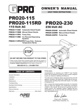
1. Mixing Paddles This mixer is equipped with rubber
mixing blades for the mixing of plaster and mortar.
ALWAYS clean the paddles after each use.
2. Bag Cutter This feature allows mixing bags to be
opened easily, allowing the contents of the bag to fall
directly into the mixing drum.
3. Hydraulic Motor — Bidirectional hydraulic motor is
used in conjunction with the directional control valve to
operate the hydraulic dump cylinder and paddle shaft.
4. Hydraulic Paddle Control Lever — Push this
three-position lever inward for clockwise rotation of
the paddle blades. Place in the center position for no
rotation (neutral/off).
5. Hydraulic Dump Lever — Push this lever inward to
activate the dump cylinders.
6. Latch — Use this latch to secure the engine
compartment enclosure.
7. Hydraulic Pump — Supplies hydraulic fluid to the
hydraulic control valve.
8. Hydraulic Oil Sight Gauge This gauge indicates
the level and temperature of the hydraulic oil. For
normal operation, the oil level should be visible at the
midpoint on the sight gauge.
9. Adjustable Stabilizer Jack Stands — Use these jack
stands to adjust the mixer to the desired height.
10. Mixing Drum — Drum capacity is 20 cubic feet
(566 liters). Mixing materials such as mortar and plaster
are placed into this drum for mixing. ALWAYS clean
the drum after each use.
11. Shaft Seals There is a Zerk grease fitting at each
end of the mixing drum. These grease fittings lubricate
the paddle shaft seals. Fittings require daily greasing
with lithium-based EP grease.
12. Drum Bearing There is a pillow block bearing on
each end of the mixing drum. Bearings require daily
greasing with lithium-based EP grease.
13. Hydraulic Dump Cylinder When activated, these
cylinders will cause the mixing drum to rotate to the
dump position.
14. Pivot Point/Zerk Fitting There is a Zerk grease
fitting on each end of the mixing drum. These fittings
lubricate the dumping mechanism. Lubricate both
fittings at least twice a week.
15. Emergency Stop Switch This switch is located
on the side of the engine cover. When activated, it will
shut down the engine.
16. Safety Grill — Provided for operator safety. This safety
grill is designed to keep hands and solid objects out
of the mixing drum when in use. This grill should be
closed at all times while the mixer is in use. DO NOT
remove the grill or grill opening bar. Keep the grill clean
by washing it down daily.
17. Forklift Pockets When lifting of the mixer is
required, use these forklift pockets to lift the mixer.
Remember to insert the forks of the forklift a minimum
of 24 inches into the forklift pockets.
18. Hydraulic Oil Filter — 10-micron hydraulic filter. Filters
out small particles that are harmful to the hydraulic
system.
19. Hydraulic Valve — Directional hydraulic control valve.
Controls the direction of hydraulic fluid supplied to the
dump cylinder and paddle shaft.
20. Swivel Jack Stands These jack stands swivel out
to support the mixer.
21. Engine Cover — Lift this cover to gain access to the
engine.
COMPONENTS (MIXER)
PAGE 16 — PRO20 HYDRAULIC MIXER • OPERATION MANUAL — REV. #1 (09/09/19)
COMPONENTS (ENGINE)
Figure 3. Engine Components
2
3
4
5
6
8
9
10
13
5
3
7
1
11
14
12
1. Air Cleaner — Prevents dirt and other debris from
entering the fuel system. Turn the knobs on the sides of
the air cleaner cover to gain access to the filter element.
2. Oil Dipstick — Remove to check the amount and
condition of oil in the crankcase.
3. Oil Filler Cap — Remove to add the recommended
type of oil listed in Table 4. Make sure the cap is
tightened securely. DO NOT overfill.
4. Fuel Pump — Draws fuel from the fuel tank into the
engine.
5. Spark Plug — Provides spark to the ignition system.
Set the spark plug gap to 0.030 in. (0.76 mm). Clean
the spark plug once a week.
6. Electric Starter — Starts the engine when the ignition
key is rotated to the ON position.
7. Oil Drain Plug — Remove to drain oil from the
crankcase.
NOTICE
Operating the engine without an air filter or with a
damaged or worn air filter will allow dirt to enter the
engine, causing rapid engine wear.
8. Ignition Switch/Keys — Insert the ignition key here
to start the engine. Turn the key clockwise to the ON
position, then continue turning clockwise to the START
position and release when the engine starts. To stop
the engine, turn the key fully counterclockwise to the
STOP position.
9. Recoil Starter — Manual starting mechanism. Pull
the starter grip slowly until resistance is felt, then pull
briskly and smoothly to start the engine.
10. Throttle Lever — Adjusts engine speed (RPM). Place
the lever in the UP (rabbit) position for FAST speed.
Place the lever in the DOWN (turtle) position for SLOW
speed.
11. Fuel Tank — Holds up to 12.0 quarts (11.4 liters) of
unleaded gasoline. Refer to the manufacturer’s engine
manual for additional information.
12. Fuel Filler Cap — Remove to add unleaded gasoline to
the fuel tank. Make sure the cap is tightened securely.
DO NOT overfill.
13. Choke Lever — Used in the starting of a cold engine,
or in cold weather conditions. The choke enriches the
fuel mixture.
14. Oil Filter — Prevents dirt and other debris from entering
the engine. Service the oil filter as recommended in the
maintenance section of this manual.
PRO20 HYDRAULIC MIXER • OPERATION MANUAL — REV. #1 (09/09/19) — PAGE 17
PADDLE BLADE ADJUSTMENT
STEEL DRUM
DRUM SIDE
CAST PADDLE
DRUM END
CORRECT
INCORRECT
ROTATION
SIDE PADDLE BLADE
PADDLE BLADE
IS TOO TIGHT
AGAINST DRUM
SIDE WALLS
CORRECT
INCORRECT
END PADDLE BLADE
ROTATION
PADDLE BLADE
IS TOO TIGHT
AGAINST DRUM
SIDE WALLS
Figure 4. Paddle Blade Adjustment
PAGE 18 — PRO20 HYDRAULIC MIXER • OPERATION MANUAL — REV. #1 (09/09/19)
INSPECTION
BEFORE STARTING
1. Read the safety instructions at the
beginning of this manual.
2. Clean the mixer, removing dirt and
dust—particularly the engine cooling
air inlet, carburetor, and air cleaner.
3. Check the air filter for dirt and dust. If the air filter is
dirty, replace it with a new one as required.
4. Check the carburetor for external dirt and dust. Clean
with dry compressed air.
5. Check fastening nuts and bolts for tightness.
HARDWARE
Check all hardware on the mixer before starting. Periodically
inspect all hardware. Loose hardware can contribute to
early component failure and poor performance. Keep all
mixer hardware components tight.
ENGINE OIL
1. Place the mixer on secure, level ground with the engine
stopped.
2. Remove the engine oil dipstick (Figure 5) from the
engine and wipe it clean.
Figure 5. Engine Oil Dipstick
ENGINE OIL
DIPSTICK
3. Reinsert the dipstick back into its holder, then remove
it again. Check the oil level (Figure 6) shown on the
dipstick.
Figure 6. Engine Oil Level
4. If the oil level is low, remove the oil filler cap
(Figure 7) and fill to the edge of the oil filler hole with
the recommended oil type listed in Table 4. DO NOT
overfill. Maximum oil capacity is 48 oz. (1.4 liters).
Figure 7. Oil Filler Cap
ADD
ADD
OIL
FULL
LIMIT
OIL FILLER
CAP
Table 4. Oil Type
Season Temperature Oil Type
Summer 25°C or higher SAE 10W-30
Spring/Fall 25°C–10°C SAE 10W-30/20
Winter 0°C or lower SAE 10W-10
PRO20 HYDRAULIC MIXER • OPERATION MANUAL — REV. #1 (09/09/19) — PAGE 19
INSPECTION
FUEL
1. Remove the fuel filler cap (Figure 8) located on top of
the fuel tank.
Figure 8. Fuel Inspection
2. Visually inspect the fuel level inside the fuel tank. If
fuel is low, replenish with unleaded gasoline. Be sure
to use a strainer for filtration while refueling.
DANGER
Motor fuels are highly flammable
and can be dangerous if mishandled.
DO NOT smoke while refueling. DO NOT
attempt to refuel the pump if the engine is
hot or running.
FUEL
FILLER CAP
DANGER
DO NOT top off fuel. Wipe up any spilled fuel
immediately.
EMERGENCY STOP SWITCH
The engine emergency stop switch (Figure 9) should be
tested every time the engine is started.
Figure 9. Emergency Stop Switch
HYDRAULIC OIL
Check the hydraulic oil sight gauge (Figure 10) to ensure
that the hydraulic oil is at the midway level.
Figure 10. Hydraulic Oil Sight Gauge
EMERGENCY
STOP SWITCH
CAUTION
NEVER disable or disconnect the emergency stop
switch. It is provided for operator safety. Injury may result
if it is disabled, disconnected or improperly maintained.
HYDRAULIC OIL
SIGHT GAUGE
PAGE 20 — PRO20 HYDRAULIC MIXER • OPERATION MANUAL — REV. #1 (09/09/19)
INSPECTION
HYDRAULIC HOSES
Check hydraulic hoses to make sure they are not worn,
frayed or defective.
GREASE FITTINGS (SHAFT SEALS)
Check the Zerk grease fittings (Figure 11) at each end
of the mixing drum. These grease fittings lubricate the
paddle shaft seals. Grease daily with lithium-based EP
grease, preferably at the end of the day. Grease until visible
inside the drum to ensure that the cavity area is free of
contamination.
Figure 11. Grease Fittings (Bearings and Seals)
PILLOW BLOCK
BEARING
ZERK GREASE
FITTING
ZERK GREASE
FITTING
GREASE FITTINGS (PILLOW BLOCK BEARINGS)
Check the Zerk grease fittings underneath each of the pillow
block bearings (Figure 11). Grease daily with two shots of
lithium-based EP grease.
GREASE FITTINGS (DUMP CYLINDERS)
Check the Zerk grease fittings on each of the dump
cylinders (Figure 12). These grease fittings lubricate the
hydraulic dumping mechanism. Grease with one shot of
lithium-based EP grease every week.
Figure 12. Grease Fittings (Dump Cylinders)
ZERK
FITTING CAP
ZERK
FITTING CAP
ZERK GREASE
FITTING
ZERK GREASE
FITTING
DUMP CYLINDER
  • Page 1 1
  • Page 2 2
  • Page 3 3
  • Page 4 4
  • Page 5 5
  • Page 6 6
  • Page 7 7
  • Page 8 8
  • Page 9 9
  • Page 10 10
  • Page 11 11
  • Page 12 12
  • Page 13 13
  • Page 14 14
  • Page 15 15
  • Page 16 16
  • Page 17 17
  • Page 18 18
  • Page 19 19
  • Page 20 20
  • Page 21 21
  • Page 22 22
  • Page 23 23
  • Page 24 24
  • Page 25 25
  • Page 26 26
  • Page 27 27
  • Page 28 28
  • Page 29 29
  • Page 30 30
  • Page 31 31
  • Page 32 32
  • Page 33 33
  • Page 34 34
  • Page 35 35
  • Page 36 36

MQ Multiquip PRO20 Operating instructions

Type
Operating instructions

MQ Multiquip PRO20: The Next Level in Plaster and Mortar Mixing

The MQ Multiquip PRO20 Hydraulic Plaster/Mortar Mixer is a powerful and versatile machine designed to make your mixing tasks easier and more efficient. With its 18HP gasoline engine and hydraulic system, the PRO20 can handle even the toughest jobs with ease.

Features:

  • 18HP Vanguard gasoline engine for reliable power
  • Hydraulic system for smooth and efficient mixing
  • Durable steel drum with a capacity of 6 cubic feet
  • Adjustable paddle blades for a variety of mixing applications
  • Safety grate to prevent hands from entering the drum

Ask a question and I''ll find the answer in the document

Finding information in a document is now easier with AI