Page is loading ...

O P E R A T I N G I N S T R U C T I O N S
Lector61x
Image-based code reader

Described product
Lector61x
Manufacturer
SICK AG
Erwin-Sick-Str. 1
79183 Waldkirch
Germany
Legal information
This work is protected by copyright. Any rights derived from the copyright shall be
reserved for SICK AG. Reproduction of this document or parts of this document is only
permissible within the limits of the legal determination of Copyright Law. Any modifica‐
tion, abridgment or translation of this document is prohibited without the express writ‐
ten permission of SICK AG.
The trademarks stated in this document are the property of their respective owner.
© SICK AG. All rights reserved.
Original document
This document is an original document of SICK AG.
2
O P E R A T I N G I N S T R U C T I O N S | Lector61x 8024830/17IL/2020-04-02 | SICK
Subject to change without notice

Contents
1 About this document........................................................................ 5
1.1 Information on the operating instructions.............................................. 5
1.2 Scope......................................................................................................... 5
1.3 Explanation of symbols............................................................................ 5
1.4 Further information................................................................................... 6
2 Safety information............................................................................ 7
2.1 Intended use............................................................................................. 7
2.2 Improper use............................................................................................. 7
2.3 Internet protocol (IP) technology.............................................................. 8
2.4 Limitation of liability................................................................................. 8
2.5 Modifications and conversions................................................................ 8
2.6 Requirements for skilled persons and operating personnel.................. 8
2.7 Operational safety and particular hazards.............................................. 9
3 Product description........................................................................... 12
3.1 Product ID.................................................................................................. 12
3.2 Scope of delivery....................................................................................... 13
3.3 Product characteristics............................................................................ 14
4 Transport and storage....................................................................... 18
4.1 Transport................................................................................................... 18
4.2 Unpacking.................................................................................................. 18
4.3 Transport inspection................................................................................. 18
4.4 Storage...................................................................................................... 18
5 Mounting............................................................................................. 20
5.1 Mounting instructions............................................................................... 20
5.2 Preparation for mounting......................................................................... 20
5.3 Mounting location..................................................................................... 21
5.4 Mounting the device................................................................................. 27
5.5 Mounting the read cycle sensor (optional).............................................. 28
6 Electrical installation........................................................................ 29
6.1 Safety......................................................................................................... 29
6.2 Wiring instructions.................................................................................... 32
6.3 Connection diagrams............................................................................... 33
6.4 Pin assignments of electrical connections............................................. 35
6.5 Connecting the device.............................................................................. 36
7 Commissioning.................................................................................. 42
7.1 Configuring the device with SOPAS ET.................................................... 42
7.2 Configuring the device via the button without configuration software
(SOPAS ET)................................................................................................ 43
7.3 Initial commissioning................................................................................ 44
CONTENTS
8024830/17IL/2020-04-02 | SICK O P E R A T I N G I N S T R U C T I O N S | Lector61x
3
Subject to change without notice

8 Maintenance...................................................................................... 46
8.1 Maintenance plan..................................................................................... 46
8.2 Cleaning..................................................................................................... 46
9 Troubleshooting................................................................................. 49
9.1 General faults, warnings, and errors....................................................... 49
9.2 Displaying the status log.......................................................................... 49
9.3 SICK service.............................................................................................. 49
9.4 Repairs...................................................................................................... 49
9.5 Returns...................................................................................................... 49
9.6 Replacing the device................................................................................ 50
10 Decommissioning............................................................................. 52
10.1 Disposal..................................................................................................... 52
11 Technical data.................................................................................... 53
11.1 Features.................................................................................................... 53
11.2 Mechanics/electronics............................................................................. 54
11.3 Performance............................................................................................. 54
11.4 Interfaces.................................................................................................. 55
11.5 Ambient data............................................................................................. 56
12 Accessories........................................................................................ 57
13 Annex.................................................................................................. 58
13.1 EU declaration of conformity / Certificates............................................. 58
13.2 Signal assignment of cables with open cable end at one end.............. 58
13.3 Connection diagrams of connection module CDB650-204.................. 59
13.4 Connection diagrams of connection module CDM420-0006............... 68
13.5 Copyright notices...................................................................................... 77
13.6 General cybersecurity notice................................................................... 77
CONTENTS
4
O P E R A T I N G I N S T R U C T I O N S | Lector61x 8024830/17IL/2020-04-02 | SICK
Subject to change without notice

1 About this document
1.1 Information on the operating instructions
These operating instructions provide important information on how to use devices from
SICK AG.
Prerequisites for safe work are:
•
Compliance with all safety notes and handling instructions supplied.
•
Compliance with local work safety regulations and general safety regulations for
device applications
The operating instructions are intended to be used by qualified personnel and electrical
specialists.
NOTE
Read these operating instructions carefully to familiarize yourself with the device and its
functions before commencing any work.
The operating instructions are an integral part of the product. Store the instructions in
the immediate vicinity of the device so they remain accessible to staff at all times.
Should the device be passed on to a third party, these operating instructions should be
handed over with it.
These operating instructions do not provide information on operating the machine or
system in which the device is integrated. For information about this, refer to the operat‐
ing instructions of the specific machine.
1.2 Scope
These operating instructions serve to incorporate the device into a customer system.
Instructions are given by stages for all actions required.
These operating instructions apply to all available device types of the product. To obtain
more detailed information on identifying your device type, see "Type code", page 12.
Available device types are listed on the online product page:
•
www.sick.com/Lector61x
Commissioning is described using one particular device type as an example and based
on the default parameter settings for the relevant device.
1.3 Explanation of symbols
Warnings and important information in this document are labeled with symbols. Signal
words introduce the instructions and indicate the extent of the hazard. To avoid acci‐
dents, damage, and personal injury, always comply with the instructions and act care‐
fully.
DANGER
… indicates a situation of imminent danger, which will lead to a fatality or serious
injuries if not prevented.
WARNING
… indicates a potentially dangerous situation, which may lead to a fatality or serious
injuries if not prevented.
ABOUT THIS DOCUMENT 1
8024830/17IL/2020-04-02 | SICK O P E R A T I N G I N S T R U C T I O N S | Lector61x
5
Subject to change without notice

CAUTION
… indicates a potentially dangerous situation, which may lead to minor/slight injuries if
not prevented.
NOTICE
… indicates a potentially harmful situation, which may lead to material damage if not
prevented.
NOTE
… highlights useful tips and recommendations as well as information for efficient and
trouble-free operation.
1.4 Further information
NOTE
Further documentation for the device can be found on the online product page at:
•
www.sick.com/Lector61x
There, additional information has been provided depending on the product, such as:
•
Model-specific online data sheets for device types, containing technical data,
dimensional drawing, and specification diagrams
•
EU declarations of conformity for the product family
•
Dimensional drawings and 3D CAD dimension models of the device types in vari‐
ous electronic formats
•
This documentation, available in English and German, and in other languages if
necessary
•
Other publications related to the devices described here
•
Publications dealing with accessories
Documents on request
Overview of command strings for the device.
1 ABOUT THIS DOCUMENT
6
O P E R A T I N G I N S T R U C T I O N S | Lector61x 8024830/17IL/2020-04-02 | SICK
Subject to change without notice

2 Safety information
2.1 Intended use
The Lector61x image-based code reader is an intelligent ID sensor.
The device is used for automatic, stationary identification and decoding of codes on
moving or stationary objects. The device reads all commonly used 1D codes (bar
codes/stacked codes) and 2D codes (matrix codes). The device uses its host interface
to send the read data to a higher-level computer (e.g. PLC) for coordinating further pro‐
cessing.
The device is suitable for industrial and logistics applications that require stable and
fast reading of codes. The device meets the applicable requirements for industrial
robustness, interfaces and data processing.
SICK AG assumes no liability for losses or damage arising from the use of the product,
either directly or indirectly. This applies in particular to use of the product that does not
conform to its intended purpose and is not described in this documentation.
2.1.1 Conditions for specified enclosure rating
To ensure compliance with the specified IP54 enclosure rating of the device during
operation, the following requirements must be met: If these requirements are not met,
the device does not fulfill any specified enclosure rating.
•
The two electrical M12 connections must be tightly screwed to the contacted
female connector or male connector.
•
The Ethernet connection, if not used, must be sealed with a tightly-fastened pro‐
tective plug (as in the delivery condition).
2.2
Improper use
Any use outside of the stated areas, in particular use outside of the technical specifica‐
tions and the requirements for intended use, will be deemed to be incorrect use.
•
The device does not constitute a safety component in accordance with the respec‐
tive applicable safety standards for machines.
•
The device must not be used in explosion-hazardous areas, in corrosive environ‐
ments or under extreme environmental conditions.
•
The device must not be operated in the temperature range below 0 °C.
•
Any use of accessories not specifically approved by SICK AG is at your own risk.
WARNING
Danger due to improper use!
Any improper use can result in dangerous situations.
Therefore, observe the following information:
■
Product should be used only in accordance with its intended use.
■
All information in these operating instructions must be strictly observed.
■
Shut down the product immediately in case of damage.
SAFETY INFORMATION 2
8024830/17IL/2020-04-02 | SICK O P E R A T I N G I N S T R U C T I O N S | Lector61x
7
Subject to change without notice

2.3 Internet protocol (IP) technology
NOTE
SICK uses standard IP technology in its products. The emphasis is placed on availability
of products and services.
SICK always assumes the following prerequisites:
•
The customer ensures the integrity and confidentiality of the data and rights
affected by its own use of the aforementioned products.
•
In all cases, the customer implements the appropriate security measures, such as
network separation, firewalls, virus protection, and patch management.
2.4 Limitation of liability
Relevant standards and regulations, the latest technological developments, and our
many years of knowledge and experience have all been taken into account when com‐
piling the data and information contained in these operating instructions. The manufac‐
turer accepts no liability for damage caused by:
■
Non-adherence to the product documentation (e.g., operating instructions)
■
Incorrect use
■
Use of untrained staff
■
Unauthorized conversions or repair
■
Technical modifications
■
Use of unauthorized spare parts, consumables, and accessories
With special variants, where optional extras have been ordered, or owing to the latest
technical changes, the actual scope of delivery may vary from the features and illustra‐
tions shown here.
2.5 Modifications and conversions
NOTICE
Modifications and conversions to the device may result in unforeseeable dangers.
Interrupting or modifying the device or SICK software will invalidate any warranty claims
against SICK AG. This applies in particular to opening the housing, even as part of
mounting and electrical installation.
2.6
Requirements for skilled persons and operating personnel
WARNING
Risk of injury due to insufficient training.
Improper handling of the device may result in considerable personal injury and material
damage.
■
All work must only ever be carried out by the stipulated persons.
This product documentation refers to the following qualification requirements for the
various activities associated with the device:
2 SAFETY INFORMATION
8
O P E R A T I N G I N S T R U C T I O N S | Lector61x 8024830/17IL/2020-04-02 | SICK
Subject to change without notice

■
Instructed personnel have been briefed by the operator about the tasks assigned
to them and about potential dangers arising from improper action.
■
Skilled personnel have the specialist training, skills, and experience, as well as
knowledge of the relevant regulations, to be able to perform tasks delegated to
them and to detect and avoid any potential dangers independently.
■
Electricians have the specialist training, skills, and experience, as well as knowl‐
edge of the relevant standards and provisions, to be able to carry out work on elec‐
trical systems and to detect and avoid any potential dangers independently. The
electrician must comply with the provisions of the locally applicable work safety
regulation.
The following qualifications are required for various activities:
Table 1: Activities and technical requirements
Activities Qualification
Mounting, maintenance
■
Basic practical technical training
■
Knowledge of the current safety regulations in the workplace
Electrical installation,
device replacement
■
Practical electrical training
■
Knowledge of current electrical safety regulations
■
Knowledge of the operation and control of the devices in their
particular application
Commissioning, configura‐
tion
■
Basic knowledge of the Windows
TM
operating system in use
■
Basic knowledge of the design and setup of the described con‐
nections and interfaces
■
Basic knowledge of data transmission
■
Basic knowledge of 1D technology (bar code) or 2D technology
(Data Matrix code)
Operation of the device for
the particular application
■
Knowledge of the operation and control of the devices in their
particular application
■
Knowledge of the software and hardware environment for the
particular application
2.7 Operational safety and particular hazards
Please observe the safety notes and the warnings listed here and in other chapters of
this product documentation to reduce the possibility of risks to health and avoid dan‐
gerous situations.
LEDs on the product
The feedback LED, the LED alignment aid, and the status LEDs of the product are clas‐
sified as risk group 0.
The accessible radiation from LEDs of risk group 0 does not pose a risk to eyes or skin.
The product is fitted with LEDs in risk group 1 for object illumination.
SAFETY INFORMATION 2
8024830/17IL/2020-04-02 | SICK O P E R A T I N G I N S T R U C T I O N S | Lector61x
9
Subject to change without notice

CAUTION
Warning! Optical radiation: LED risk group 1
The LEDs may pose a danger to the eyes and skin in the event of incorrect use.
■
Protect the eyes and skin against radiation.
■
Use suitable eye protection.
■
Use protective measures such as a screen to shield the radiation.
■
Do not open the housing. Opening the housing will not switch off the light source.
Opening the housing may increase the level of risk.
■
Comply with the current national regulations on photobiological security of lamps
and lamp systems.
Time-of-flight sensor (invisible infrared light, distance measurement in configuration
mode)
CAUTION
Optical radiation: Laser class 1
The accessible radiation does not pose a danger when viewed directly for up to 100
seconds. It may pose a danger to the eyes and skin in the event of incorrect use.
■
Do not open the housing. Opening the housing may increase the level of risk.
■
Current national regulations regarding laser protection must be observed.
Caution – Use of controls or adjustments or performance of procedures other than
those specified herein may result in hazardous radiation exposure.
For both radiation types:
It is not possible to entirely rule out temporary disorienting optical effects, particularly
in conditions of dim lighting. Disorienting optical effects may come in the form of daz‐
zle, flash blindness, afterimages, photosensitive epilepsy, or impairment of color vision,
for example.
DANGER
Risk of injury due to hot device surface.
The surface of the device can become hot during operation.
•
Before performing work on the device (e.g. mounting, cleaning, disassembly),
switch off the device and allow it to cool down.
•
Ensure good dissipation of excess heat from the device to the surroundings.
WARNING
Electrical voltage!
Electrical voltage can cause severe injury or death.
■
Work on electrical systems must only be performed by qualified electricians.
■
The power supply must be disconnected when attaching and detaching electrical
connections.
■
The product must only be connected to a voltage supply as set out in the require‐
ments in the operating instructions.
■
National and regional regulations must be complied with.
■
Safety requirements relating to work on electrical systems must be complied with.
2 SAFETY INFORMATION
10
O P E R A T I N G I N S T R U C T I O N S | Lector61x 8024830/17IL/2020-04-02 | SICK
Subject to change without notice

WARNING
Risk of injury and damage caused by potential equalization currents!
Improper grounding can lead to dangerous equipotential bonding currents, which may
in turn lead to dangerous voltages on metallic surfaces, such as the housing. Electrical
voltage can cause severe injury or death.
■
Work on electrical systems must only be performed by qualified electricians.
■
Follow the notes in the operating instructions.
■
Install the grounding for the product and the system in accordance with national
and regional regulations.
SAFETY INFORMATION 2
8024830/17IL/2020-04-02 | SICK O P E R A T I N G I N S T R U C T I O N S | Lector61x
11
Subject to change without notice

3 Product description
3.1 Product ID
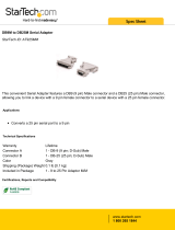
3.1.1 Type label
The type label gives information for identification of the device.
Lector61x
V2D61XX- XXXXXX
XXXXXXX
XXXX XXXX
DC 12-24V 3,5W
Imax = 1,5A
SICK D-79276 Reute
Made
Exchange
2019
in Malaysia
5
9
6
4
3
3
2
1
7
8
2
1
XXXXXXX
XXXX XXXX
V2D61XX
MAC
-
XXXXXX
00:00:00:00:00:00
Pre-configured
Lector
25
Figure 1: Structure of the type labels on the device
1
Type designation according to type code
2
Part number
3
Serial number
4
Supply voltage, power consumption and maximum current consumption
5
DataMatrix code with product data (part number, serial number, MAC address)
6
Manufacturer and production location
7
Date of manufacture
8
MAC address (placeholder)
9
Conformity mark and certification mark
3.1.2 Type code
The devices of the Lector61x product family are arranged according to the following
type code:
V2D61yz- abcdefg
V2D 6 1 y z - a b c d e f g
1 2 3 4 5 6 7 8 9 10 11 12 13
Position Description Characteristic
1 Device name type V2D: Vision 2D matrix
2 Product family 6: 6xx
3 Platform / housing 1: Standard line
4 Resolution of the image sensor 0: 0.3 Mpx (640 px x 480 px)
1: 1.2 Mpx
3 PRODUCT DESCRIPTION
12
O P E R A T I N G I N S T R U C T I O N S | Lector61x 8024830/17IL/2020-04-02 | SICK
Subject to change without notice

Position Description Characteristic
5 Function D: Reading with DPM and OCR
6 Separator "-"
7 generation "empty": 1. generation
8 Imager type / color M: Monochrome (black-and-white)
9 Optical M: Manual focus
10 Integrated illumination unit /
LED alignment aid
S: Integrated illumination unit (visible amber
light, visible blue light), LED alignment aid (visi‐
ble red light), ToF (Time of Flight, invisible
infrared light)
11 Focal length / aperture B: 6 mm
C: 12 mm
12 Data interface E: Ethernet with 0.25 m cable (female connec‐
tor, M12, 4-pin, D-coded), RS232C and CAN
with 0.35 m cable (male connector, M12, 17-
pin, A-coded)
13 IP protection class 4: IP54
NOTE
Not all combinations are possible according to the type code. The available device
types can be found online at:
•
www.sick.com/Lector61x
3.2 Scope of delivery
The delivery of the device includes the following components:
Table 2: Scope of delivery
No. of
units
Component Comment
1 Device in the version ordered M12 female connector for Ethernet sealed with
tightly-fastened protective plug .
Without bracket.
1 Printed safety notes, multilin‐
gual
Brief information on the safe use of the product.
1 Protective plug To seal off the M12 female connector of the Ether‐
net connection if the interface is not being used.
The screwed in protective plug maintains, in this
case, the IP54 enclosure rating of the device.
1 Focus adjustment tool For manual focus adjustment.
Associated components not contained in the delivery:
Table 3: Other components
Component Comment
SOPAS ET configuration software Available online at:
•
www.sick.com/SOPAS_ET
This documentation, available in English
and German, and in other languages if
necessary
Available online at:
•
www.sick.com/Lector61x
PRODUCT DESCRIPTION 3
8024830/17IL/2020-04-02 | SICK O P E R A T I N G I N S T R U C T I O N S | Lector61x
13
Subject to change without notice

Accessories
Accessories such as brackets and additional connecting cables are only delivered if the
accessories have been ordered separately, see "Accessories", page 57.
3.3 Product characteristics
3.3.1 Device view
1 2
3
3
3
3
6
7
1 2
4
5
20.81
(0.82)
19.47
(0.77)
40.28 (1.59)
43.8 (1.72)
29.6 (1.17)
13.9
(0.55)
25 (0.98)
50 (1.97)
40.28 (1.59)
20.81
(0.82)
19.47
(0.77)
Figure 2: structure and device dimensions, unit: mm (inch), decimal separator: period
1
Connecting cable with “Ethernet” connection (female connector, M12, 4-pin, D-coded),
length of cable: 0.25 m
2
Connecting cable with “Power/Serial Data/CAN/I/O” connection (male connector, M12,
17-pin, A-coded), length of cable: 0.35 m
3
4 tapped blind holes, M4, 6.4 mm deep for mounting the device
4
Viewing window with 8 integrated illumination LEDs, 2 LED alignment aids, 1 feedback
LED, 1 time-of-flight sensor
5
Optics, manual focus adjustment with the help of a focus adjustment tool
6
6 status LEDs to display the focus position and working distance, device status, and
device function (3 display levels)
7
Function button
3 PRODUCT DESCRIPTION
14
O P E R A T I N G I N S T R U C T I O N S | Lector61x 8024830/17IL/2020-04-02 | SICK
Subject to change without notice

3.3.1.1 Illumination unit
3
4
1
1
1
1
1
1
2
2
1
1
Figure 3: Ilumination unit (integrated illumination)
1
8 integrated illumination LEDs (color: 4 visible amber light, 4 visible blue light)
2
2 LED alignment aids, can be deactivated (color: visible red light)
3
Feedback LED (color: visible green light, visible red light; green e.g. for Good Read, red
e.g. for No Read)
4
Time-of-flight sensor for measuring the working distance in configuration mode (color:
invisible infrared light)
NOTE
To avoid being dazzled by the integrated illumination unit, do not look into the viewing
window of the device.
3.3.2 Display and operating elements
Ready
5070120200300
Light
Test
Aiming
Focus
U-Def
L/A Eth
Tuning
Result
3
4
2
1
Figure 4: Status LEDs (3 display levels) and function button on the side of the housing
1
First display level: distance displays (focus position and working distance) in configuration
mode
2
Second display level: device status in read mode
PRODUCT DESCRIPTION 3
8024830/17IL/2020-04-02 | SICK O P E R A T I N G I N S T R U C T I O N S | Lector61x
15
Subject to change without notice

3
Third display level: selected device function
4
Function button
Distance displays
The distance displays (first display level) are provided for the purpose of adjusting the
focus position, see "Adjusting the focus position", page 23. The LEDs, when the first
display level is active, indicate the working distance and the focus position that has
been set.
Device status
Table 4: Device status (second display level)
Display LED
(green)
LED
(red)
LED
(yellow)
Status
Ready
O o
- The device is ready for use.
o O
- The device is not ready for use: hardware fault or soft‐
ware error.
Result
O o
- The read was successful.
o O
- The read was unsuccessful.
Light
O
- - Read mode: illumination on, internal reading interval
open.
U-Def - -
O
Data output via the host interface.
L/A Eth
Ö
- - Data traffic via the Ethernet interface.
O = lights up; Ö = flashes; o = does not light up
Device functions
Table 5: Device functions (third display level)
Function Description
Test Check the code reading stability: The device records a series of images
and uses the current reading performance settings to decode them. To
assess the code reading stability, check the feedback LED.
Aiming Switch the LED alignment aid on and off: By switching off the LED align‐
ment aid, the user can ensure that the LED alignment aid does not
affect the code reading. To switch the LED alignment aid back on again,
run the Aiming function again.
Focus Adjust the focus position: The focus position can be adjusted with the
help of the focus adjustment tool, see "Adjusting the focus position",
page 23.
Tuning The device adjusts itself automatically to suit the lighting conditions
and the quality of the code presented. The device stores these deter‐
mined values permanently.
The Tuning function is not supported for OCR detection or pharmacodes.
Function button and device functions in configuration mode
The function button is used to call up device functions manually without using a com‐
puter. On the third display level, the LEDs indicate the selectable device functions and
the execution of a device function. For more information on the configuration steps, see
"Configuring the device via the button without configuration software (SOPAS ET)",
page 43.
PROFINET operation (single port)
The Ready status LED signals the device status in the PROFINET network.
3 PRODUCT DESCRIPTION
16
O P E R A T I N G I N S T R U C T I O N S | Lector61x 8024830/17IL/2020-04-02 | SICK
Subject to change without notice

Table 6: Device status in the PROFINET network (first display level, Ready status LED)
Ready LED Device status Remarks
Green com‐
ponents
Red compo‐
nents
O o
Device is ready for use.
O Ö
Red compo‐
nents flash
cyclically
The device status in the
PROFINET network
depends on the flashing
frequency of the red LED
components.
Flashes
every 7 sec‐
onds
Network detection in the
device is active.
After switching on, the device detects
a PROFINET network and activates
the PROFINET protocol. The duration
of network detection can be config‐
ured in SOPAS ET (default: 3 min‐
utes). Network detection can be
deactivated in SOPAS ET.
Flashes
every
0.5 seconds
PROFINET is activated in
the device.
PROFINET is activated in the device.
The device is not connected to the
PLC or the device is not configured.
Ö Ö
PROFINET is activated in
the device.
Prerequisite: the “Flashing” function
was activated for the device in the
configuration software of the PLC
(device identification).
O = lights up; Ö = flashes; o = does not light up
3.3.3 Product features and functions
The Lector61x image-based code reader with integrated LED illumination is used to reli‐
ability detect and decode 1D codes (bar codes/stacked codes) and 2D codes (matrix
code). The device sends the read data to a higher-level computer (e.g. PLC) via the host
interface for further centralized processing.
Thanks to its compact housing, the device can also be used where space is limited. The
flexible lighting concept allows consistent code identification, regardless of the surface
or code color. The device can read the codes reliably even for small codes, short read‐
ing distances, weak contrasts, contamination or low code quality. Visible LED alignment
aids simplify the process of aligning the device to the code to be scanned. A time-of-
flight sensor measures the working distance of the device using invisible infrared light.
The focus position can be manually adjusted on the device with the help of a focus
adjustment tool.
The device does not come with an Aux serial interface. An application-specific parame‐
ter set created in SOPAS ET can therefore only be manually saved and archived as a
project file on the computer.
PRODUCT DESCRIPTION 3
8024830/17IL/2020-04-02 | SICK O P E R A T I N G I N S T R U C T I O N S | Lector61x
17
Subject to change without notice

4 Transport and storage
4.1 Transport
For your own safety, please read and observe the following notes:
NOTICE
Damage to the product due to improper transport.
■
The device must be packaged for transport with protection against shock and
damp.
■
Recommendation: Use the original packaging as it provides the best protection.
■
Transport should be performed by trained specialist staff only.
■
The utmost care and attention is required at all times during unloading and trans‐
portation on company premises.
■
Note the symbols on the packaging.
■
Do not remove packaging until immediately before you start mounting.
4.2
Unpacking
■
To protect the device against condensation, allow it to equilibrate with the ambient
temperature before unpacking if necessary.
■
Handle the device with care and protect it from mechanical damage.
■
To avoid ingress of dust and water, only remove the protective caps of the electri‐
cal connections just before attaching the connecting cable.
4.3 Transport inspection
Immediately upon receipt in Goods-in, check the delivery for completeness and for any
damage that may have occurred in transit. In the case of transit damage that is visible
externally, proceed as follows:
■
Do not accept the delivery or only do so conditionally.
■
Note the scope of damage on the transport documents or on the transport com‐
pany's delivery note.
■
File a complaint.
NOTE
Complaints regarding defects should be filed as soon as these are detected. Damage
claims are only valid before the applicable complaint deadlines.
4.4 Storage
Store the device under the following conditions:
■
Recommendation: Use the original packaging.
■
Electrical connections are provided with a protective cap (as in the delivery condi‐
tion).
■
Do not store outdoors.
■
Store in a dry area that is protected from dust.
■
So that any residual damp can evaporate, do not package in airtight containers.
■
Do not expose to any aggressive substances.
■
Protect from sunlight.
■
Avoid mechanical shocks.
■
Storage temperature: see "Technical data", page 53.
4 TRANSPORT AND STORAGE
18
O P E R A T I N G I N S T R U C T I O N S | Lector61x 8024830/17IL/2020-04-02 | SICK
Subject to change without notice

■
Relative humidity: see "Technical data", page 53.
■
For storage periods of longer than 3 months, check the general condition of all
components and packaging on a regular basis.
TRANSPORT AND STORAGE 4
8024830/17IL/2020-04-02 | SICK O P E R A T I N G I N S T R U C T I O N S | Lector61x
19
Subject to change without notice

5 Mounting
5.1 Mounting instructions
•
Observe the technical data.
•
Protect the sensor from direct and indirect sunlight.
•
To prevent condensation, avoid exposing the device to rapid changes in tempera‐
ture.
•
The mounting site has to be designed for the weight of the device.
5.2 Preparation for mounting
5.2.1 Installation requirements
DANGER
Risk of injury due to hot device surface.
The surface of the device can become hot during operation.
•
Before performing work on the device (e.g. mounting, cleaning, disassembly),
switch off the device and allow it to cool down.
•
Ensure good lost heat transfer from the device.
•
Typical space requirement: see "Field of view diagrams", page 24 and type-spe‐
cific dimensional drawing.
•
Comply with the technical data, such as the permitted ambient conditions for oper‐
ation of the device, see "Technical data", page 53.
•
Ensure good dissipation of excess heat from the device to the surroundings, in
particular at higher ambient temperatures. Ensure that there is good heat transfer
from the device, for example via the bracket to the mounting base, or ensure that
the back of the device is a sufficient distance from the wall of a housing.
•
The device must be mounted using the tapped blind holes provided for this pur‐
pose.
•
Mount the device in a shock and vibration insulated manner.
•
Make sure the device has a clear view of the codes.
Auxiliary equipment required
■
Mounting bracket with sufficient load-bearing capacity and suitable dimensions.
■
Four or two M4 screws for mounting the device on a bracket supplied by the cus‐
tomer. The screw length depends on the mounting base (wall thickness of the
bracket). Two M3 screws can optionally be used to mount the device on a bracket
supplied by the customer (screw length: at least 35 mm). When using an optional
SICK mounting bracket, the screws for mounting are included with delivery.
■
Tool and tape measure.
5.2.2 Mounting systems
Mount the device on the mounting bracket by means of a minimum of two tapped blind
holes (M4).
The tapped blind holes are located on the right and left side of the device.
SICK offers prefabricated mounting brackets that are optimally suited for mounting the
device, see "Accessories", page 57.
Customer-supplied mounting brackets
A customer-supplied mounting bracket must meet the following requirements:
5 MOUNTING
20
O P E R A T I N G I N S T R U C T I O N S | Lector61x 8024830/17IL/2020-04-02 | SICK
Subject to change without notice
/