
Baumer Document No. 81178192 01 HART FDS
Document Title: CombiPress
TM
PFMN/PFMH HART Field Device Specification - Revision 1.0 Page 1 of 26
Release Date: 7
th
of October, 2015
HART
®
Field Device Specification
Baumer CombiPress
TM
PFMN/PFMH
Revision 1
Document 81178192, rev. 1
Initial release: 7
th
of October 2015
Current release: 7
th
of October 2015
Author: Bo Wellejus Simmons
Baumer A/S
Runetoften 19
DK-8210
DENMARK
®
HART is a registered trademark of the HART Communication Foundation

Baumer Document No. 81178192 01 HART FDS
Document Title: CombiPress
TM
PFMN/PFMH HART Field Device Specification - Revision 1.0 Page 2 of 26
Release Date: 7
th
of October, 2015
1 Table of Contents
1 Table of Contents ........................................................................................................................ 2
2 Introduction ................................................................................................................................. 4
2.1 Scope ............................................................................................................................................ 4
2.2 Purpose ......................................................................................................................................... 4
2.3 Who should use this document?................................................................................................... 4
2.4 Abbreviations and definitions ........................................................................................................ 4
2.5 References .................................................................................................................................... 4
3 Device Identification ................................................................................................................... 5
4 Product Overview ....................................................................................................................... 5
5 Product Interfaces ...................................................................................................................... 6
5.1 Process Interface .......................................................................................................................... 6
Sensor Input Channels ................................................................................................................. 6 5.1.1
5.2 Host interface ................................................................................................................................ 6
Analog Output: Process pressure ................................................................................................. 6 5.2.1
5.3 Local Interfaces............................................................................................................................. 6
Local Controls and Displays ......................................................................................................... 6 5.3.1
6 Device Variables ......................................................................................................................... 6
7 Dynamic Variables ...................................................................................................................... 7
8 Status Information ...................................................................................................................... 8
8.1 Device Status ................................................................................................................................ 8
8.2 Extended Device Status ............................................................................................................... 8
8.3 Additional Device Status (Command #48) .................................................................................... 8
9 Universal Commands ............................................................................................................... 11
9.1 Supported Universal Commands ................................................................................................ 11
10 Special notes on Universal Commands ................................................................................. 11
11 Common-Practice Commands ................................................................................................ 12
11.1 Supported Common Practice Commands .................................................................................. 12
11.2 Special notes on Common Practice Commands ........................................................................ 12
12 Pressure Family Commands ................................................................................................... 13
12.1 Supported Pressure Family Commands ..................................................................................... 13
General Pressure Device Family Commands (Read) ................................................................ 13 12.1.1
12.2 Special notes on Pressure Family Commands ........................................................................... 13
13 Device-Specific Commands ..................................................................................................... 14
13.1 Command #130 – Read Minimum And Maximum Measure Pressure Values............................ 14
13.2 Command #131 – Reset Minimum And Maximum Measure Pressure Values ........................... 14
13.3 Command #132 – Read Output Current Minimum And Maximum Limits................................... 14
13.4 Command #133 – Write Ouput Current Minimum And Maximum Limits .................................... 15
13.5 Command #134 – Read Sensor Offset And Gain ....................................................................... 15
13.6 Command #135 – Write Sensor Offset And Gain ....................................................................... 15
13.7 Command #138 – Read Table Value .......................................................................................... 16
13.8 Command #139 – Write Table Value .......................................................................................... 16
13.9 Command #140 – Read Product Data ....................................................................................... 17
13.10 Command #141 – Write Pressure And Temperature Unit .......................................................... 17
13.11 Command #142 – Read Current Output Range ......................................................................... 17
13.12 Command #143 – Write Current Output Range ......................................................................... 17
13.13 Command #144 – Read Error Current Output Value .................................................................. 18
13.14 Command #145 – Write Error Current Output Value .................................................................. 18
14 Pressure Family Device Specific Tables ................................................................................ 19
14.1 Pressure Family Device Spec. Table 1 – Pressure Device Family Device Variable Status ....... 19

Baumer Document No. 81178192 01 HART FDS
Document Title: CombiPress
TM
PFMN/PFMH HART Field Device Specification - Revision 1.0 Page 3 of 26
Release Date: 7
th
of October, 2015
14.2 Pressure Family Device Specific Table 2 – Pressure Status 0 ................................................... 19
14.3 Pressure Family Device Specific Table 3 – Pressure Family Capabilities 0 ............................... 19
14.4 Pressure Family Device Specific Table 4 – Pressure Family Capabilities 1 ............................... 20
15 Device Specific Tables ............................................................................................................. 20
15.1 Cell Type Codes .......................................................................................................................... 20
15.2 Features Codes .......................................................................................................................... 20
15.3 Process Connection Position Codes .......................................................................................... 20
15.4 Electrical Connection Codes ....................................................................................................... 21
15.5 Nipple Type Codes...................................................................................................................... 21
15.6 Nipple Material Codes ................................................................................................................ 21
15.7 Coating Codes ............................................................................................................................ 21
15.8 Abs/Rel Codes ............................................................................................................................ 21
15.9 Safety Codes .............................................................................................................................. 22
15.10 Fill Material Codes ...................................................................................................................... 22
15.11 Unit Codes .................................................................................................................................. 22
16 Performance .............................................................................................................................. 22
16.1 Sampling Rates........................................................................................................................... 22
16.2 Power-Up .................................................................................................................................... 22
16.3 Reset ........................................................................................................................................... 23
16.4 Self-Test ...................................................................................................................................... 23
16.5 Command Response Times ....................................................................................................... 23
16.6 Busy and Delayed-Response ..................................................................................................... 23
16.7 Long Messages........................................................................................................................... 23
16.8 Non-Volatile Memory .................................................................................................................. 23
16.9 Modes ......................................................................................................................................... 23
16.10 Burst Mode .................................................................................................................................. 23
16.11 Write Protection .......................................................................................................................... 23
16.12 Catch Device Variable................................................................................................................. 23
16.13 Damping ...................................................................................................................................... 23
Annex A. Capability Checklist .................................................................................................................. 24
Annex B. Default Configuration ............................................................................................................... 25
Annex C. Revision History ....................................................................................................................... 26

Baumer Document No. 81178192 01 HART FDS
Document Title: CombiPress
TM
PFMN/PFMH HART Field Device Specification - Revision 1.0 Page 4 of 26
Release Date: 7
th
of October, 2015
2 Introduction
2.1 Scope
Baumer CombiPress
TM
PFMN/PFMH HART pressure transmitter has built-in support for the HART 7.4
protocol. Since the HART version of the transmitter operates identically with the non-HART version of the
transmitter, this document focuses solely on the HART functionalities of the transmitter. For all other
operational aspects of the transmitter, please consult the data sheet and the operators instructions.
This document contains the necessary data for an operator, familiar with the HART protocol, to access all
functions of the transmitter from a master system.
2.2 Purpose
This specification is designed to complement other documentation (e.g., the Operators instructions for
CombiPress
TM
, type PFMx) by providing a complete, unambiguous description of this Field Device from a
HART Communication perspective
2.3 Who should use this document?
The specification is designed to be a technical reference for HART capable Host Application Developers,
System Integrators and knowledgeable End Users. It also provides functional specifications (e.g., commands,
enumerations and performance requirements) used during Field Device development, maintenance and
testing. This document assumes the reader is familiar with HART Protocol requirements and terminology.
2.4 Abbreviations and definitions
CT Common Table
DT Device Specific Table
uint-8 8-bit unsigned integer, representing value 0 .. 255, can also be used for single bit flags
uint-16 16-bit unsigned integer, representing value 0 .. 65535
float 32-bit IEEE-754 (IEC 559) compatible single floating point variable
ASCII ISO Latin-1 (ISO 8859) string text
packed HART specific Packed ASCII format
PV Primary Variable
SV Secondary Variable
2.5 References
HART Smart Communications Protocol Specification. HCF_SPEC-12. Available from the HCF.
Operators instructions CombiPress
TM
, type PFMx, Document 11120948. Available from
www.baumer.com.

Baumer Document No. 81178192 01 HART FDS
Document Title: CombiPress
TM
PFMN/PFMH HART Field Device Specification - Revision 1.0 Page 5 of 26
Release Date: 7
th
of October, 2015
3 Device Identification
Manufacturer Name:
Baumer
Model Name(s):
CombiPress
TM
PFMx
Manufacture ID Code:
96
(60 Hex)
Device Type Code:
240
(F0 Hex)
HART Protocol Revision
7.4
Device Revision:
1
Number of Device Variables
4
Physical Layers Supported
FSK
Physical Device Category
Transmitter
4 Product Overview
The CombiPress
TM
PFMN/PFMH is a loop powered 4-20mA pressure transmitter, that comes in both an
industrial and a hygienic version, for which both absolute and relative pressure transmitters are available. The
HART version of the transmitters have the HART signal connected directly on the 4-20mA pressure output.
The transmitter also features an internal temperature sensor, used for internal temperature compensation of
the pressure. The temperature measured is only avaliable via digital communication, either via HART, on the
Baumer FlexProgram or on an attached CombiView DFON display.

Baumer Document No. 81178192 01 HART FDS
Document Title: CombiPress
TM
PFMN/PFMH HART Field Device Specification - Revision 1.0 Page 6 of 26
Release Date: 7
th
of October, 2015
5 Product Interfaces
5.1 Process Interface
Sensor Input Channels 5.1.1
The pressure sensors come in many different shapes and for many different pressure ranges.
The pressure sensor also acts a temperature sensor, providing a temperature reading of the media
temperature, which is used for temperature compensation, as well as being availabe for digital readout.
5.2 Host interface
The transmitter has a single 4-20mA current output channel, configurable with linear over-range from 3.5 to 23
mA. Within the 4 to 20 mA range, a 30 point pressure table can be used to make non-linear pressure-to-
current output. This current output channel supports HART Communication on the HART version of the
transmitter.
The error output current, to be used in case of transmitter error, is fully configurable in the range 3.5 to 23 mA.
Direction
Values (% of range)
Values (mA or V)
Linear over-range
Down
-3.13% to -0.01%
3.50 to 3.99 mA
Up
100.01% to 118.75%
20.01 to 23.00 mA
Device malfunction indication
Fixed value
-3.13% to 118.75%
3.50 to 23.00 mA
Maximum current
118.75%
23.0 mA
Multi-Drop current draw
4.0 mA
Lift-off voltage
10.0 V
Analog Output: Process pressure 5.2.1
The two-wire 4-20mA pressure loop current output is connected on two terminals marked
“Supply“ (+/-). Refer to the Operating instructions for detail on connecting the device.
The output current corresponds to the transmitter’s Primary Variable, which is the device variable for pressure.
HART Communication is supported on this current loop output.
5.3 Local Interfaces
Local Controls and Displays 5.3.1
This device can be attached to a DFON display, providing local in-situ measurement readout and configuration
possibilities. A DFON display is connected with the provided flat ribbon cable provided with the display unit.
FlexProgram configuration is also possible on the two Com. terminals 1 and 2. A PC and a Baumer
FlexProgrammer 9701 must be used for this. Standalone configuration with the FlexProgrammer is also
possible, using the FlexProgrammer 9701 as a vessel for configuration data.
Please refer to the Operating instructions manual for more information.
6 Device Variables
This Field Device does not expose any Device Variables.
DV No.
Name
Description
Unit codes
Classification
code
0, 246
Pressure
PV
Process Pressure
2 “Hg
5 mmHg
6 psi
7 bar
8 mbar
10 kg/cm
2
12 kPa
14 atm
177 ´H
2
0
65 Pressure

Baumer Document No. 81178192 01 HART FDS
Document Title: CombiPress
TM
PFMN/PFMH HART Field Device Specification - Revision 1.0 Page 7 of 26
Release Date: 7
th
of October, 2015
237 MPa
238 “H
2
0
239 mmH
2
0
241 mH
2
0 (dev. spec.)
1, 247
Temperature
SV
Cell temperature
32 ⁰C
33 ⁰F
64 Temperature
3, 244
Percent of Range
Output in % of full scale
57 %
0 Not Class’d
4, 245
Loop Current
Loop Current associated with
Device Variable 0,
representing process pressure
39 mA
84 Current
Only Pressure (PV) and Temperature (SV) allow changing of unit codes.
The different H
2
0 column units are defined at 4 ⁰C.
NOTE: Device specific unit code mH
2
0 is used instead of HCF common table unit code for mH
2
0.
7 Dynamic Variables
Two Dynamic Variables are implemented.
Dyn var.
Meaning
Unit codes
PV
Pressure
2 “Hg
5 mmHg
6 psi
7 bar
8 mbar
10 kg/cm
2
12 kPa
14 atm
177 ´H
2
0
237 MPa
238 “H
2
0
239 mmH
2
0
241 mH
2
0 (dev. spec.)
SV
Temperature
32 ⁰C
33 ⁰F

Baumer Document No. 81178192 01 HART FDS
Document Title: CombiPress
TM
PFMN/PFMH HART Field Device Specification - Revision 1.0 Page 8 of 26
Release Date: 7
th
of October, 2015
8 Status Information
8.1 Device Status
The Field Device Status byte is contained in the second data byte in messages from the device.
The following table defines the meaning of the different status bits.
Bit
Definition
Description
7
Device Malfunction
Is set if an electronic defect or memory defect is
detected.
6
Configuration Changed
Is set if a HART command results in writing new data
to a configuration register.
The bit is set no matter if the value written is changed
or identical to the already stored value.
5
Cold Start
Is set upon restart. It is reset for each master after
responding to the first command from that specific
master.
4
More Status Available
NOT USED
3
Loop Current Fixed
This bit is set if device is running with fixed loop
current, eg. in Fixed Current Mode (Command 40) or
if Loop Current Signaling mode is turned off (e.g. in
Multidrop Mode).
2
Loop Current Saturated
Is set if the loop current is capped by either the upper
or lower current limits.
1
Non-Primary Variable Out of
Limits
Is set if SV is high or low limited.
0
Primary Variable Out of Limits
Is set if PV is high or low limited.
8.2 Extended Device Status
Extended Device Status is returned along with Additional Device Status by HART Command 48. Two bits are
supported in this device.
Bit
Definition
Description
3..7
NOT USED
2
Critical Power Failure
Is set if the device detects that the power supply is
not performing as expected.
1
Device Variable Alert
This bit is set if any Device Variable is
simulated/fixed, or the environmental conditions are
out of range. It will also be se if an electronic defect
or memory defect is detected.
0
NOT USED
8.3 Additional Device Status (Command #48)
Command #48 returns 14 bytes of data, with the following status information:
Byte
Bit
Definition
Description
0
Device Specific Error Status Flags
7-2
NOT USED
1
ADC Comm Error
Is set if ADC communication fails
0
Wire Break
Is set if wire break is detected
1
Device Specific 0
7-0
NOT USED
2
Device Specific 1
7-0
NOT USED
3
Device Specific 2
7-0
NOT USED

Baumer Document No. 81178192 01 HART FDS
Document Title: CombiPress
TM
PFMN/PFMH HART Field Device Specification - Revision 1.0 Page 9 of 26
Release Date: 7
th
of October, 2015
4
Device Specific 3
7-0
NOT USED
5
Device Specific 4
7-0
NOT USED
6
Extended Device Status
7-3
NOT USED
2
Critical Power Failure
See Extended Device Status
1
Device Variable Alert
See Extended Device Status
0
NOT USED
7
NOT USED
7-0
NOT USED
8
Standardized Status 0
7
NOT USED
6
Electronic Defect
Is set in case of wire break
5
Environment Conditions out of
Range
This bit is set if either ambient temperatures are out
of range.
4
Power Supply Conditions out of
Range
Is set if the device detects that the power supply is
not performing as expected.
3
Watchdog Reset Executed
This bit is set in case of the watchdog resetting the
device, in case of firmware running into a software
dead-lock.
2
Non-volatile Memory Defect
This bit is set if a problem with the system memory is
detected.
1
Device Variable Simulation Active
Is set if any device variable is being simulated, e.g.
by in-factory system test.
0
NOT USED
9
Standardized Status 1
7-3
NOT USED
2
Event Notification Overflow
This bit is set if the internal processor becomes
overworked, not able to execute all tasks given within
the allowed time.
1
Discrete Variable Simulation
Is set if any device variable is being simulated, e.g.
by in-factory system test.
0
Simulation Active
Is set if any device variable is being simulated, e.g.
by in-factory system test.
Table continues on next page ..

Baumer Document No. 81178192 01 HART FDS
Document Title: CombiPress
TM
PFMN/PFMH HART Field Device Specification - Revision 1.0 Page 10 of 26
Release Date: 7
th
of October, 2015
.. table continued from previous page.
10
Analog Channel Saturated
7-2
NOT USED
1
Analog Channel 1
Is set if Analog Channel 1 is capped by either the
upper or lower current limit.
0
NOT USED
11
Standardized Status 2
7-0
NOT USED
12
Standardized Status 3
7-0
NOT USED
13
Analog Channel Fixed
7-3
NOT USED
1
Analog Channel 1
Is set if Analog Channel 1 is fixed by either Fixed
Current Mode (Command 40) or if Loop Current
Signaling mode is turned off (e.g. in Multidrop Mode).
It can also be caused by a running in-factory system
test.
0
NOT USED
NOT USED bits are always set to 0.
These status bits are updated immediately before and immediatley after each command to the device is
handled..

Baumer Document No. 81178192 01 HART FDS
Document Title: CombiPress
TM
PFMN/PFMH HART Field Device Specification - Revision 1.0 Page 11 of 26
Release Date: 7
th
of October, 2015
9 Universal Commands
9.1 Supported Universal Commands
All Universal Commands are mandatory and are supported. Following Universal Commands are implemented:
0 Read Unique Identifier
1 Read Primary Variable
2 Read Loop Current And Percent Of Range
3 Read Dynamic Variables And Loop Current
6 Write Polling Address
7 Read Loop Configuration
8 Read Dynamic Variable Classifications
9 Read Device Variables with Status
11 Read Unique Identifier Associated With Tag
12 Read Message
13 Read Tag, Descriptor, Date
14 Read Primary Variable Transducer Information
15 Read Device Information
16 Read Final Assembly Number
17 Write Message
18 Write Tag, Descriptor, Date
19 Write Final Assembly Number
20 Read Long Tag
21 Read Unique Identifier Associated With Long Tag
22 Write Long Tag
38 Reset Configuration Changed Flag
48 Read Additional Device Status
10 Special notes on Universal Commands
Command #3: Returns PV and SV. This totals in 14 data bytes.
Command #9: This command supports up to 4 device variables. This totals in up to 37 data bytes, including
the time stamp.
If more than 4 device variables are requested, only the first 4 are returned, along with a warning.
Command #14: Transducer serial number is not supported. The units code for limits and minimum span is
equal to that of the Primary Variable.
Command #15: Write protect is not implemented, and Write Protect Code is therefore always returned as
“251” (None). The unit code for Primary Variable range values is the same as is used for the Primary Variable.

Baumer Document No. 81178192 01 HART FDS
Document Title: CombiPress
TM
PFMN/PFMH HART Field Device Specification - Revision 1.0 Page 12 of 26
Release Date: 7
th
of October, 2015
11 Common-Practice Commands
11.1 Supported Common Practice Commands
The following common-practice commands are implemented:
34 Write Primary Variable Damping Value
35 Write Primary Variable Range Values
36 Set Primary Variable Upper Range Value
37 Set Primary Variable Lower Range Value
38 Reset "Configuration Changed" Flag
40 Enter/Exit Fixed Current Mode
42 Perform Device Reset
43 Set Primary Variable Zero
44 Write Primary Variable Units
45 Trim Loop Current Zero
46 Trim Loop Current Gain
47 Write Primary Variable Transfer Function
48 Read Additional Device Status
50 Read Dynamic Variable Assignment
80 Read Device Variable Trim Points
81 Read Device Variable Trim Guidelines
82 Write Device Variable Trim Point
83 Reset Device Variable Trim Points
11.2 Special notes on Common Practice Commands
Command #45: Prior to issuing this command, the loop current must be fixed at exactly 4.000mA (set with
command 40).
Command #46: Prior to issuing this command, the loop current must be fixed at exactly 20.000mA (set with
command 40).
Command #48: Returns 14 bytes of data.
Command #80: This command can only be used on PV / Device Variable 0.
Command #81: This command can only be used on PV / Device Variable 0.
Command #82: This command can only be used on PV / Device Variable 0.
Command #83: This command can only be used on PV / Device Variable 0.

Baumer Document No. 81178192 01 HART FDS
Document Title: CombiPress
TM
PFMN/PFMH HART Field Device Specification - Revision 1.0 Page 13 of 26
Release Date: 7
th
of October, 2015
12 Pressure Family Commands
The following conductivity family commands are taken from the Pressure Family Specification revision 1.0,
Draft L.
The upper byte of all the 16-bit command codes is set to 0x05 for Pressure Family Commands, and in theory
there are command codes enough for 256 commands in the family, from 0x0500 to 0x05FF.
For details on the Pressure Family Commands, please refer to the Pressure Device Family Specification
HCF_SPEC-160.5, available from the HART Communications Foundation.
12.1 Supported Pressure Family Commands
Implemented pressure family commands are as follows:
General Pressure Device Family Commands (Read) 12.1.1
1280 Read Pressure Status
1281 Read Capabilities
1282 Read Supported Status Mask
1283 Read Pressure Sensor Information
1284 Read Process Connection
1285 Read Associated Device Variables
12.2 Special notes on Pressure Family Commands
Command #1283: On the CombiPress
TM
PFMN / PFMH the returned Minimum Absolute Pressure represents
the Lower Range of the sensor, while Maximum Static Pressure represents the Upper Range of the sensor.

Baumer Document No. 81178192 01 HART FDS
Document Title: CombiPress
TM
PFMN/PFMH HART Field Device Specification - Revision 1.0 Page 14 of 26
Release Date: 7
th
of October, 2015
13 Device-Specific Commands
The following device-specific commands are implemented:
Command 130 – Read Minimum And Maximum Measured Pressure Values
Command 131 – Reset Minimum And Maximum Measured Pressure Values
Command 132 – Read Output Current Mainiml and Maximum Limits
Command 133 – Write Output Current Mainiml and Maximum Limits
Command 134 – Read Sensor Offset And Gain
Command 135 – Write Sensor Offset And Gain
Command 138 – Read Table Value
Command 139 – Write Table Value
Command 140 – Read Product Data
Command 141 – Write Pressure And Temperature Unit
Command 142 – Read Current Output Range
Command 143 – Write Current Output Range
Command 144 – Read Error Current Output Value
Command 145 – Write Error Current Output Value
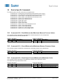
13.1 Command #130 – Read Minimum And Maximum Measure Pressure Values
This command returns the Minimum and Maximum measured pressure since startup/reset.
The values are of the currently selected unit.
Request data frame
Byte
Format
Description
-
-
No request bytes
Response data frame
Byte
Format
Description
0..3
float
Minimum Measured Value
4..7
float
Maximum Measured Value
13.2 Command #131 – Reset Minimum And Maximum Measure Pressure Values
This command resets the Minimum and Maximum measured pressure since startup/reset.
Request data frame
Byte
Format
Description
-
-
No request bytes
Response data frame
Byte
Format
Description
-
-
No response bytes
13.3 Command #132 – Read Output Current Minimum And Maximum Limits
This command returns the Minimum and Maximum limits for the output loop current.
The output will not go beyond this current.
Request data frame
Byte
Format
Description
-
-
No request bytes
Response data frame
Byte
Format
Description
0..3
float
Output Current Minimum Limit
4..7
float
Output Current Maximum Limit

Baumer Document No. 81178192 01 HART FDS
Document Title: CombiPress
TM
PFMN/PFMH HART Field Device Specification - Revision 1.0 Page 15 of 26
Release Date: 7
th
of October, 2015
13.4 Command #133 – Write Ouput Current Minimum And Maximum Limits
This command is used to setup the Minimum and Maximum limits for the output loop current.
The unit used is mA.
Request data frame
Byte
Format
Description
0..3
float
Output Current Minimum Limit
4..7
float
Output Current Maximum Limit
Response data frame
Byte
Format
Description
0..3
float
Output Current Minimum Limit
4..7
float
Output Current Maximum Limit
Command specific Response Codes
Code
Type
Description
10
Error
Current Minimum Limit Too Low
11
Error
Current Maximum Limit Too High
12
Error
Current Minimum Limit Is higher Than Current Maximum Limit
13
Error
Current Minimum Limit And Current Maximum Limit Are Both Out Of Range
13.5 Command #134 – Read Sensor Offset And Gain
This command is used read the sensor offset and gain values.
Request data frame
Byte
Format
Description
-
-
No request bytes
Response data frame
Byte
Format
Description
0..3
float
Sensor Offset Value
4..7
float
Sensor Gain Value
CombiPress
TM
PFMN / PFMH specific: The returned values represent gain factor and offset values for the PV.
The offset is of the currently active PV unit. Default gain is 1 and offset is 0 bar.
13.6 Command #135 – Write Sensor Offset And Gain
This command is used to setup new values for the sensor offset and gain.
Request data frame
Byte
Format
Description
0..3
float
Sensor Offset Value
4..7
float
Sensor Gain Value
Response data frame
Byte
Format
Description
0..3
float
Sensor Offset Value
4..7
float
Sensor Gain Value
Command specific Response Codes
Code
Type
Description
9
Error
Offset Value Too High
10
Error
Offset Value Too Low
11
Error
Gain Value Too High
12
Error
Gain Value Too Low
13
Error
Offset And Gain Values Are Both Out Of Limits
CombiPress
TM
PFMN / PFMH specific:
The written values represent gain factor and offset values for the PV. The offset must be of the currently active
PV unit. Default gain is 1 and offset is 0 bar.

Baumer Document No. 81178192 01 HART FDS
Document Title: CombiPress
TM
PFMN/PFMH HART Field Device Specification - Revision 1.0 Page 16 of 26
Release Date: 7
th
of October, 2015
13.7 Command #138 – Read Table Value
This command is used read values of the specified table point.
The table is used for linearization in the pressure to loop current output conversion. Each table point is
comprised of a Pressure Value and an associated Loop Current Value. For pressure values in between two
points on the table, the appropriate loop current value is linearly interpolated.
Request data frame
Byte
Format
Description
0
uint-8
Table Point Number
Response data frame
Byte
Format
Description
0
uint-8
Table Point Number
1
uint-8
Number Of Table Points
2..5
float
Table Point Pressure Value
6..9
float
Table Point Loop Current Value
CombiPress
TM
PFMN / PFMH specific:
The unit of the Loop Current Value is mA, while The Pressure value is of the currently selected pressure unit.
NOTE: In conformance with the FlexBar HRT (which is replaced by the CombiPress), table point numbers are
in the range 1 through 30, and not 0 throught 29 which would be the most common notation.
13.8 Command #139 – Write Table Value
This command is used to write the specified table point. It also sets the number of table points.
The table is used for linearization in the pressure to loop current output conversion. Each table point is
comprised of a Pressure Value and an associated Loop Current Value. For pressure values in between two
points on the table, the appropriate loop current value is linearly interpolated.
Request data frame
Byte
Format
Description
0
uint-8
Table Point Number
1
uint-8
Number Of Table Points
2..5
float
Table Point Pressure Value
6..9
float
Table Point Loop Current Value
Response data frame
Byte
Format
Description
0
uint-8
Table Point Number
1
uint-8
Number Of Table Points
2..5
float
Table Point Pressure Value
6..9
float
Table Point Loop Current Value
CombiPress
TM
PFMN / PFMH specific:
The unit of the Loop Current Value is mA, while The Pressure value is of the currently selected pressure unit.
NOTE: In conformance with the FlexBar HRT (which is replaced by the CombiPress), table point numbers are
in the range 1 through 30, and not 0 throught 29 which would be the most common notation.

Baumer Document No. 81178192 01 HART FDS
Document Title: CombiPress
TM
PFMN/PFMH HART Field Device Specification - Revision 1.0 Page 17 of 26
Release Date: 7
th
of October, 2015
13.9 Command #140 – Read Product Data
This command is used read Baumer specific product data. These are not necessarily connected to common
values of the HART specification.
Request data frame
Byte
Format
Description
-
-
No request bytes
Response data frame
Byte
Format
Description
0
uint-8
Cell Type
1
uint-8
Features
2
uint-8
Process Connection Position
3
uint-8
Electrical Connection
4
uint-8
Nipple Type
5
uint-8
Nipple Material
6
uint-8
Coating
7
uint-8
Abs/Rel
8
uint-8
Safety
9
uint-8
Fill Material
13.10 Command #141 – Write Pressure And Temperature Unit
This command is used to setup both the pressure unit and the cell temperature unit at the same time.
Request data frame
Byte
Format
Description
0
uint-8
Pressure Unit (CT 2)
1
uint-8
Cell Temperature Unit (CT 2)
Response data frame
Byte
Format
Description
0
uint-8
Pressure Unit (CT 2)
1
uint-8
Cell Temperature Unit (CT 2)
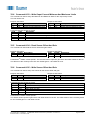
13.11 Command #142 – Read Current Output Range
This command returns the current range of the Loop Current output in the unit of mA.
Request data frame
Byte
Format
Description
-
-
No request bytes
Response data frame
Byte
Format
Description
0..3
float
Loop Current Output at 0%
4..7
float
Loop Current Output at 100%
13.12 Command #143 – Write Current Output Range
This command sets up the current range of the Loop Current output in the unit of mA.
Request data frame
Byte
Format
Description
0..3
float
Loop Current Output at 0%
4..7
float
Loop Current Output at 100%
Response data frame
Byte
Format
Description
0..3
float
Loop Current Output at 0%
4..7
float
Loop Current Output at 100%
Command specific Response Codes
Code
Type
Description
10
Error
Loop Current At 0% Too Low
11
Error
Loop Current At 100% Too High
12
Error
Loop Current At 0% Is Higher Than Loop Current At 100%
13
Error
Loop Current At 0% And 100% Are Both Out Of Range

Baumer Document No. 81178192 01 HART FDS
Document Title: CombiPress
TM
PFMN/PFMH HART Field Device Specification - Revision 1.0 Page 18 of 26
Release Date: 7
th
of October, 2015
13.13 Command #144 – Read Error Current Output Value
This command returns the value of the Loop Current output used to indicate error conditions, in the unit of mA.
Request data frame
Byte
Format
Description
-
-
No request bytes
Response data frame
Byte
Format
Description
0..3
float
Loop Current Output at Error
13.14 Command #145 – Write Error Current Output Value
This command sets up the value of the Loop Current output used to indicate error conditions, in the unit of mA.
Request data frame
Byte
Format
Description
0..3
float
Loop Current Output at Error
Response data frame
Byte
Format
Description
0..3
float
Loop Current Output at Error
Command specific Response Codes
Code
Type
Description
10
Error
Error Loop Current Too Low
11
Error
Error Loop Current Too High

Baumer Document No. 81178192 01 HART FDS
Document Title: CombiPress
TM
PFMN/PFMH HART Field Device Specification - Revision 1.0 Page 19 of 26
Release Date: 7
th
of October, 2015
14 Pressure Family Device Specific Tables
14.1 Pressure Family Device Spec. Table 1 – Pressure Device Family Device
Variable Status
Code
Description
0x01
Reserved
0x02
Reserved
0x04
Reserved
0x08
More Device Variable Status Available
0x30
Limit Status:
11 Constant (i.e. value cannot be changed by the process)
01 Low Limited (eg. A/D Converter has reached its lower limit)
10 High Limited (eg. A/D Converter has reached its upper limit)
00 Not Limited
0xC0
Process Data Quality Status:
11 Good
01 Poor accuracy (eg. value is beyond rated conductivity or hardware zoom, temperature out of
range)
10 Manual / Fixed (eg. value is simulated or forced)
14.2 Pressure Family Device Specific Table 2 – Pressure Status 0
Code
Description
0x01
Pressure Sensor Break
0x02
Temperature Sensor Break
0x04
Static Pressure Sensor Break
0x08
Pressure Calibration Required
0x10
Pressure Operating Range Exceeded
0x20
Temperature Operating Range Exceeded
0x40
Statuc Pressure Operating Range Exceeded
0x80
Reserved
14.3 Pressure Family Device Specific Table 3 – Pressure Family Capabilities 0
Code
Description
0x01
Command 1287 – Read Min/Max Pressure Observation (NOT IMPLEMENTED)
0x02
Command 1288 – Read Min/Max Temperature Observation (NOT IMPLEMENTED)
0x04
Command 1289 – Read Min/Max Static Pressure Observation (NOT IMPLEMENTED)
0x08
Command 1286 – Read Optional Gasket Material Data (NOT IMPLEMENTED)
0x10
Command 1290 – Read Remote Seal Information (NOT IMPLEMENTED)
0x20
Command 1408 – Write Process Connection (NOT IMPLEMENTED)
0x40
Command 1409 – Write Optional Gasket Material Data (NOT IMPLEMENTED)
0x80
Command 1410 – Write Remote Seal Information (NOT IMPLEMENTED)

Baumer Document No. 81178192 01 HART FDS
Document Title: CombiPress
TM
PFMN/PFMH HART Field Device Specification - Revision 1.0 Page 20 of 26
Release Date: 7
th
of October, 2015
14.4 Pressure Family Device Specific Table 4 – Pressure Family Capabilities 1
Code
Description
0x01
Reserved
0x02
Reserved
0x04
Reserved
0x08
Reserved
0x10
Reserved
0x20
Reserved
0x40
Reserved
0x80
Reserved
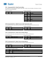
15 Device Specific Tables
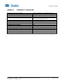
15.1 Cell Type Codes
Sensor Type codes
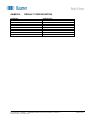
15.2 Features Codes
Features codes
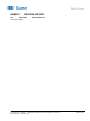
15.3 Process Connection Position Codes
Process connection position codes
Code
Description
0x01
0.0 .. 0.345 bar
0x02
-1.0 .. 1.0 bar
0x03
-1.0 .. 5.0 bar
0x04
-1.0 .. 20.0 bar
0x05
-1.0 .. 34.0 bar
0x06
-1.0 .. 68.0 bar
0x07
-1.0 .. 400.0 bar
0x81
0.0 .. 5.0 psi
0x82
-15.0 .. 15.0 psi
0x83
-15.0 .. 70.0 psi
0x84
-15.0 .. 300.0 psi
0x85
-15.0 .. 500.0 psi
0x86
-15.0 .. 1000.0 psi
0x87
-15.0 .. 5800.0 psi
Code
Description
0x41
4 .. 20mA 0.25%
0x43
4 .. 20mA + HART 0.25%
0x51
4 .. 20mA 0.10%
0x53
4 .. 20mA + HART 0.10%
Code
Description
5
Bottom process connection
6
Rear process connection
Other
Not specified
Page is loading ...
Page is loading ...
Page is loading ...
Page is loading ...
Page is loading ...
Page is loading ...
-
 1
1
-
 2
2
-
 3
3
-
 4
4
-
 5
5
-
 6
6
-
 7
7
-
 8
8
-
 9
9
-
 10
10
-
 11
11
-
 12
12
-
 13
13
-
 14
14
-
 15
15
-
 16
16
-
 17
17
-
 18
18
-
 19
19
-
 20
20
-
 21
21
-
 22
22
-
 23
23
-
 24
24
-
 25
25
-
 26
26


Baumer PFMN Operating instructions
- Type
- Operating instructions
- This manual is also suitable for
Ask a question and I''ll find the answer in the document
Finding information in a document is now easier with AI
Related papers
-
Baumer PFMH Operating instructions
-
Baumer FlexProgrammer 9701 Operating instructions
-
-
-
-
-
-
-
-
Other documents
-
Sierra 600/700 Series HART Quick Installation Guide
-
Bernard Controls Fielbus Solution HART FOR INTELLI+ Installation & Operation Manual
-
ICP HRT-227CS Quick Start
-
-
-
ABB DHH805-A Operating
-
 Remote Automation Solutions Hart Interface Programs User manual
-
Fisher DLC3010 User manual
-
Rosemount 248 Temperature Transmitter Owner's manual
-
Rosemount 3051S Series Pressure Transmitter Owner's manual
