Page is loading ...

INSTRUCTION MANUAL
120Volt, Track Pendant Head
Antique Bronze Finish
Home Depot SKU 828-650 (UPC008938241090)

Thank you for purchasing this Hampton Bay interior track pendant. This product has been manufactured with the highest standards of safety
and quality.
FEATURES:
1. Track pendant can be installed any locations into the track section.
2. Track Pendant is adjustable in length and comes complete with a Do-It-Yourself Pendant Adapter and wire; the wire can be cut to desired
lengths for different applications and ceiling heights.
QUESTIONS, PROBLEMS, MISSING PARTS:
Before returning to your local Home Depot, please call our Customer Service Team at 1-877-527-0313 or visit www.homedepot.com. Please
reference SKU828650, UPC008938241090.
GENERAL
All electrical connections must be in accordance with local codes, ordinances or national electrical codes. If you are unfamiliar with methods of
installing electrical wiring, secure the services of a qualified electrician. Before starting installation, disconnect the power by turning off the
circuit breaker or removing the fuse at fuse box. Turning the power off using the light switch is not sufficient to prevent electrical shock.
Note: The important safeguards and instructions appearing in this manual are not meant to cover all possible conditions and situations that may
occur. It must be understood that common sense, caution and care are factors that cannot be built into any product. These factors must be
supplied by the person(s) caring for, installing and operating the fixture. If at any time you are uncomfortable or are unsure of what to do,
please contact a qualified licensed electrician for further assistance.
IMPORTANT SAFETY INSTRUCTIONS
1. Read all instructions.
2. Do not install this lighting system in a damp or wet location.
3. Before energizing make sure that the lighting system is clear of all material which could cause a direct short and check all electrical
connections to make sure they are tight.
4. Do not install any part of this system (TRACK) less than 7 feet (2.2m) above floor.
5. To reduce the risk of fire and burns, do not install this lighting system where non insulated open bus-bar conductors can be shorted or
contact any conductive metals.
6. To reduce the risk of fire and overheating, make sure all connections are tight.
7. Turn off electrical power before modifying the light system in anyway.
8. For installation with HAMPTON BAY EC series track only.
9. CAUTION – To reduce the risk of a burn during re-lamping, remove from the track before re-lamping
.
10. Do not install any luminaire assembly closer than 6 inches from any curtain, or similar combustible material.
11. DANGER – RISK OF SHOCK – DISCONNECT POWER BEFORE INSTALLATION.
SAVE THESE INSTRUCTIONS
TOOLS REQUIRED FOR ASSEMBLY & INSTALLATION (not included):
Ladder Safety goggles Wire stripper Gloves Flathead screwdriver Phillips screwdriver
Electrical tape
PARTS INCLUDED FOR ASSEMBLY (parts are not to scale):
x1 canopy x1 Pendant
Fixtures x1 Hardware Packet x1 A Bulb
Box

ASSEMBLY INSTRUCTIONS (AS SHOWN IN DIAGRAM):
This pendant is already assembled and ready for installation to the track section. Proceed to Installing Fixture to Track. Section if you do not
need to adjust the length of the wire. Please follow these instructions if you do need to adjust the length of the wire.
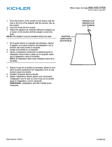
1. On the Adapter, remove the set screw on the side of the top end of the adapter as shown in Figure 1. Unscrew the bushing and slide it
down the wire a few inches. Keep these parts handy for the final installation.
2. Separate the top and bottom portions of the adaptor by unscrewing them from one another. The two parts of the adapter are joined
with screw threads inside the top and bottom section.(See Figure 1)
3. Remove the three (3) wires connected to the three (3) screws inside the top of the adapter. Loosen the knot. Remove the bottom
portion of the adapter, and the bushing from the wire.
4. 4a, Determine the distance from the ceiling where you want to hang the pendant by holding the wire at the ceiling or using a tape
measure. When the desired length is established, MARK THE WIRE WHERE IT MEETS THE CEILING.
4b, make a second mark 3 1/2in. below the first mark. Tie a knot so that it is at the top of the second mark (and between both
markings).
NOTE: If installing more than one pendant and the same height is desired for all pendants make sure the wires on all pendants are marked at
the same length.
CAUTION: Be careful not to cut or damage the insulation on the inside wires when removing the outer insulation.
5. Cut the wire 3in. above the knot.
6. The pendant wire has three (3) smaller wires running inside of it. Remove 3 inches of the outer insulation exposing the three (3)
smaller wires inside.
How to Identify the Wires: The NEUTRAL WIRE is transparent with a white line marking or simply a white wire, the HOT WIRE is
transparent without any marking or simply a black wire. The GROUND WIRE is a bare wire or simply a green wire or transparent with a green
line marking wire.
7. Replace the bushing, bottom portion of the adapter and the knot respectively. Remove a half (1/2) inch of the insulation on all three (3)
of the smaller wires, twist the copper strands and loop each wire to its own screw matching the neutral wire to the silver screw, the hot
wire to the gold screw and the ground wire to the green screw. Tighten screws to secure the wire.
8. Slide the bottom portion of the adapter up to the top and close the adapter by screwing the top and bottom together and replace set
screw.
9. Slide the bushing to the bottom of the adapter and re-attach.
Installing Fixture to Track:
1. IMPORTANT: Determine ground side of track (has indented groove on face and two internal copper bars) and connector (side of
connector with two metal tabs) It can only be installed if grounds are aligned. (See Figure 3)
2. Insert connector into track. Twist ground side of connector towards ground side of track until connector snaps into place and locks.
Installing fixture to Ceiling: (Refer to Figure 4)
If you want to install the fixture to the ceiling using the direct wire canopy, start with steps 1-3.
NOTE: These fixtures are intended to be used with a 4in. x 2-1/8in. deep metal octagon junction box. The box must be directly supported by
the building structure.
1. Install mounting bracket to existing outlet box with screws.
2. Pull the pendant wire through the bushing and the canopy.
3. To adjust the wire, follow step 4a from above. Tie the knot at the marking and cut the wire 6in. above the knot. Then follow step 6.
4. Rotate and twisted the mounting nut until the bushing secured.
5. Wire connections:
A. Make ELECTRICAL CONNECTION as directed below.
B. Carefully tuck connected wires back into the outlet box ensuring that the wire nuts do not come loose.
Install the lamp shade (For removable glass shades) (See Figure2)
Remove the retaining ring from the socket, slide the glass shade onto the socket placing it against the metal socket housing. While holding the
glass shade in place screw on the retaining ring onto the socket until it is snug. NOTE: Do not over tighten as the glass could chip or break.
ELECTRICAL CONNECTIONS
a. Connect the neutral wire from the fixture to the neutral wire of the outlet box.
b. Connect the hot wire from the fixture to the hot wire of the outlet box.
c. Connect the ground wire from the fixture to the ground wire of the outlet box.
Note: Use UL Listed wire connectors suitable for the size, type and number of conductors. No loose strands or loose wires should be present.
Secure wire connectors with UL approved electrical tape.
6. Secure the canopy to the mounting bracket with provided decorative nuts.
Install and replace light bulbs:
CAUTION: Refer to the re-lamping label located near the lamp holder for recommended maximum wattage. Do not exceed recommended
wattage.
1. Be sure the power is off, allow the fixture and bulb to cool, grasp connector and pull down while rotating it counter clockwise.
2. Twist the bulb counter clockwise from the socket to remove it. Insert a new bulb and rotate the bulb clockwise until it is secure.
3. Restore electric power.

ASSEMBLY DIAGRAM
TROUBLE SHOOTING:
PRODUCT MAINTENANCE:
1. Turn off power to the light fixture.
2. To clean the outside or inside of the fixture, first disconnect power to the fixture by turning off the circuit breaker or by removing the fuse
at the fuse box. Next, use a dry or slightly dampened clean cloth (use clean water, never use a solvent) to wipe the inside glass and interior
surface of the fixture. Allow the fixture to dry completely before power is restored.
CAUTION: Do not use chemical solvents or harsh abrasives to clean fixture as damage to the fixture or various components may occur
remedying the fixture inoperable.
LIMITED WARRANTY
The manufacturer warrants this lighting fixture to be free from defects in materials and workmanship for a period of five (5) years from date of
purchase. This warranty applies only to the original consumer purchaser and only to products used in normal use and service. If this product is
found to be defective, the manufacturer’s only obligation, and your exclusive remedy, is the repair or replacement of the product at the
manufacturer’s discretion, provided that the product has not been damaged through misuse, abuse, accident, modifications, alterations, neglect
or mishandling. This warranty shall not apply to any product that is found to have been improperly installed, set-up, or used in any way not in
accordance with the instructions supplied with the product. This warranty shall not apply to a failure of the product as a result of an accident,
misuse, abuse, negligence, alteration, or faulty installation, or any other failure not relating to faulty material or workmanship. This warranty
shall not apply to the finish on any portion of the product, such as surface and/or weathering, as this is considered normal wear and tear. The
manufacturer does not warrant and specially disclaims any warranty, whether express or implied, of fitness for a particular purpose, other than
the warranty contained herein. The manufacturer specifically disclaims any liability and shall not be liable for any consequential or incidental
loss or damage, including but not limited to any labor/expense costs involved in the replacement or repair of said product.
Problem Possible Cause Corrective Action
1. Light bulb is burned out. 1. Replace light bulb.
2. Power is off. 2. Make sure power supply is on.
3. Faulty wire connection. 3. Check wiring.
Light Bulb will not illuminate.
4. Faulty switch. 4. Test or replace switch.
Fuse blows or circuit breaker trips when
light bulb is illuminated.
Crossed wires or power wire is grounding out. Check wire connections.
Fig.2
Fig.1
Fig.3
Fig.4
NOTICE:
1. CONNECTOR IS DESIGNED TO LOCK INTO
TRACK SECTION BY TURNING CONNECTOR
IN ONE DIRECTION ONLY.
2. TURN"GROUND INDICATOR"TAB TOWARDS
THE GROUND GROOVE ON TRACK TO ALIGN
GROUND TAB WITH GROUND CONDUCTOR.
/