Daniel Ultrasonic Flow Meters-T-2 to T-11 Transducer Upgrade Operating instructions
- Type
- Operating instructions

DANIEL ULTRASONIC
METER T-2 TO T-11
TRANSDUCER UPGRADE
INSTRUCTIONS
__________________________________________
DANIEL MEASUREMENT AND CONTROL, INC.
AN EMERSON PROCESS MANAGEMENT COMPANY
HOUSTON, TEXAS
Part Number 3-9000-751
Revision A
DECEMBER 2005


IMPORTANT INSTRUCTIONS
Because these measurement instruments are sophisticated technical products, you must install, use
and maintain them in accordance with Daniel’s guidelines to ensure that they operate within the
range specified on the equipment nameplate. The following instructions must be adhered to and
integrated into your safety program when installing, using and maintaining Daniel Products.
• Read all instructions prior to installing, operating and servicing the product. If this
instruction manual is not the correct manual, call 1-713-467-6000 (24-hour response number
for both Service and Sales Support) and the requested manual will be provided. Save this
instruction manual for future reference.
• If you do not understand any of the instructions, contact your Daniel representative for
clarification.
• Follow all warnings, cautions and instructions marked on and supplied with the product.
• Inform and educate your personnel in the proper installation, operation and maintenance of
the product.
• Install your equipment as specified in the installation instructions of the appropriate
instruction manual and per applicable local and national codes. Connect all products to the
proper electrical and pressure sources.
• To ensure proper performance, use qualified personnel to install, operate, update, program
and maintain the product.
• When replacement parts are required, ensure that qualified people use replacement parts
specified by the manufacturer. Unauthorized parts and procedures can affect the product's
performance and place the safe operation of your process at risk. Look-alike substitutions
may result in fire, electrical hazards or improper operation.
• Ensure that all equipment doors are closed and protective covers are in place, except when
maintenance is being performed by qualified persons, to prevent personal injury.
• ALWAYS READ AND FOLLOW THE DANIEL ULTRASONIC METER T-2 TO T-
11 TRANSDUCER UPGRADE INSTRUCTIONS AND ALL PRODUCT WARNINGS
AND INSTRUCTIONS.
• Use of this equipment for any purpose other than its intended purpose may result in property
damage and/or serious personal injury or death.
• Before opening the flameproof enclosure in a flammable atmosphere, the electrical circuits
must be interrupted.

This page intentionally left blank.

DANIEL T-2 TO T-11 TRANSDUCER UPGRADE INSTRUCTIONS DEC 2005
PREFACE i
DANIEL MEASUREMENT AND CONTROL, INC.
DANIEL ULTRASONIC METER T-2 TO T-11
TRANSDUCER UPGRADE INSTRUCTIONS
NOTICE
DANIEL MEASUREMENT AND CONTROL, INC. ("DANIEL") SHALL NOT BE LIABLE FOR TECHNICAL OR
EDITORIAL ERRORS IN THIS MANUAL OR OMISSIONS FROM THIS MANUAL. DANIEL MAKES NO
WARRANTIES, EXPRESSED OR IMPLIED, INCLUDING THE IMPLIED WARRANTIES OF
MERCHANTABILITY AND FITNESS FOR A PARTICULAR PURPOSE WITH RESPECT TO THIS
MANUAL AND, IN NO EVENT, SHALL DANIEL BE LIABLE FOR ANY SPECIAL OR CONSEQUENTIAL
DAMAGES INCLUDING, BUT NOT LIMITED TO, LOSS OF PRODUCTION, LOSS OF PROFITS, ETC.
PRODUCT NAMES USED HEREIN ARE FOR MANUFACTURER OR SUPPLIER IDENTIFICATION ONLY
AND MAY BE TRADEMARKS/REGISTERED TRADEMARKS OF THESE COMPANIES.
THE CONTENTS OF THIS PUBLICATION ARE PRESENTED FOR INFORMATIONAL PURPOSES ONLY, AND
WHILE EVERY EFFORT HAS BEEN MADE TO ENSURE THEIR ACCURACY, THEY ARE NOT TO BE
CONSTRUED AS WARRANTIES OR GUARANTEES, EXPRESSED OR IMPLIED, REGARDING THE
PRODUCTS OR SERVICES DESCRIBED HEREIN OR THEIR USE OR APPLICABILITY. WE RESERVE THE
RIGHT TO MODIFY OR IMPROVE THE DESIGNS OR SPECIFICATIONS OF SUCH PRODUCTS AT ANY TIME.
DANIEL DOES NOT ASSUME RESPONSIBILITY FOR THE SELECTION, USE OR MAINTENANCE OF ANY
PRODUCT. RESPONSIBILITY FOR PROPER SELECTION, USE AND MAINTENANCE OF ANY DANIEL
PRODUCT REMAINS SOLELY WITH THE PURCHASER AND END-USER.
DANIEL AND THE DANIEL LOGO ARE REGISTERED TRADEMARKS OF DANIEL INDUSTRIES, INC. THE
EMERSON LOGO IS A TRADEMARK AND SERVICE MARK OF EMERSON ELECTRIC CO.
THE DANIEL ULTRASONIC GAS FLOWMETER INCLUDING THE MARK III ELECTRONICS IS COVERED
BY UNITED STATES PATENTS 5,983,730 AND 4,646,575 AND PATENTS PENDING.
COPYRIGHT © 2005
BY DANIEL MEASUREMENT AND CONTROL, INC.
HOUSTON, TEXAS, U.S.A.
All rights reserved. No part of this work may be reproduced or
copied in any form or by any means - graphic, electronic or
mechanical - without first receiving the written permission of
Daniel Measurement and Control, Inc., Houston, Texas, U.S.A.

DEC 2005 DANIEL T-2 TO T-11 TRANSDUCER UPGRADE INSTRUCTIONS
PREFACEii
WARRANTY
1. LIMITED WARRANTY: Subject to the limitations contained in Section 2 herein and except as otherwise expressly
provided herein, Daniel Measurement and Control, Inc. ("Daniel") warrants that the firmware will execute the
programming instructions provided by Daniel, and that the Goods manufactured or Services provided by Daniel will be
free from defects in materials or workmanship under normal use and care until the expiration of the applicable warranty
period. Goods are warranted for twelve (12) months from the date of initial installation or eighteen (18) months from
the date of shipment by Daniel, whichever period expires first. Consumables and Services are warranted for a period
of 90 days from the date of shipment or completion of the Services. Products purchased by Daniel from a third party for
resale to Buyer ("Resale Products") shall carry only the warranty extended by the original manufacturer. Buyer agrees
that Daniel has no liability for Resale Products beyond making a reasonable commercial effort to arrange for procurement
and shipping of the Resale Products. If Buyer discovers any warranty defects and notifies Daniel thereof in writing during
the applicable warranty period, Daniel shall, at its option, promptly correct any errors that are found by Daniel in the
firmware or Services, or repair or replace F.O.B. point of manufacture that portion of the Goods or firmware found by
Daniel to be defective, or refund the purchase price of the defective portion of the Goods/Services. All replacements or
repairs necessitated by inadequate maintenance, normal wear and usage, unsuitable power sources, unsuitable
environmental conditions, accident, misuse, improper installation, modification, repair, storage or handling, or any other
cause not the fault of Daniel are not covered by this limited warranty, and shall be at Buyer's expense. Daniel shall not
be obligated to pay any costs or charges incurred by Buyer or any other party except as may be agreed upon in writing
in advance by an authorized Daniel representative. All costs of dismantling, reinstallation and freight and the time and
expenses of Daniel's personnel for site travel and diagnosis under this warranty clause shall be borne by Buyer unless
accepted in writing by Daniel. Goods repaired and parts replaced during the warranty period shall be in warranty for the
remainder of the original warranty period or ninety (90) days, whichever is longer. This limited warranty is the only
warranty made by Daniel and can be amended only in a writing signed by an authorized representative of Daniel. Except
as otherwise expressly provided in the Agreement, THERE ARE NO REPRESENTATIONS OR WARRANTIES OF
ANY KIND, EXPRESSED OR IMPLIED, AS TO MERCHANTABILITY, FITNESS FOR PARTICULAR PURPOSE,
OR ANY OTHER MATTER WITH RESPECT TO ANY OF THE GOODS OR SERVICES. It is understood that
corrosion or erosion of materials is not covered by our guarantee.
2. LIMITATION OF REMEDY AND LIABILITY: DANIEL SHALL NOT BE LIABLE FOR DAMAGES
CAUSED BY DELAY IN PERFORMANCE. THE SOLE AND EXCLUSIVE REMEDY FOR BREACH OF
WARRANTY HEREUNDER SHALL BE LIMITED TO REPAIR, CORRECTION, REPLACEMENT OR REFUND
OF PURCHASE PRICE UNDER THE LIMITED WARRANTY CLAUSE IN SECTION 1 HEREIN. IN NO EVENT,
REGARDLESS OF THE FORM OF THE CLAIM OR CAUSE OF ACTION (WHETHER BASED IN CONTRACT,
INFRINGEMENT, NEGLIGENCE, STRICT LIABILITY, OTHER TORT OR OTHERWISE), SHALL DANIEL'S
LIABILITY TO BUYER AND/OR ITS CUSTOMERS EXCEED THE PRICE TO BUYER OF THE SPECIFIC
GOODS MANUFACTURED OR SERVICES PROVIDED BY DANIEL GIVING RISE TO THE CLAIM OR CAUSE
OF ACTION. BUYER AGREES THAT IN NO EVENT SHALL DANIEL'S LIABILITY TO BUYER AND/OR ITS
CUSTOMERS EXTEND TO INCLUDE INCIDENTAL, CONSEQUENTIAL OR PUNITIVE DAMAGES. THE
TERM "CONSEQUENTIAL DAMAGES" SHALL INCLUDE, BUT NOT BE LIMITED TO, LOSS OF
ANTICIPATED PROFITS, LOSS OF USE, LOSS OF REVENUE AND COST OF CAPITAL.

DANIEL T-2 TO T-11 TRANSDUCER UPGRADE INSTRUCTIONS DEC 2005
TABLE OF CONTENTS iii
TABLE OF CONTENTS
1.0 INTRODUCTION .................................................... 1-1
1.1 General........................................................ 1-1
2.0 BEFORE YOU BEGIN! ............................................... 2-1
2.1 Tools and Materials Required ...................................... 2-1
3.0 KEY POINTS........................................................ 3-1
4.0 TRANSDUCER UPGRADE PROCEDURE............................... 4-1
APPENDICES
APPENDIX A REMOVAL AND RE-INSTALLATION OF WRITE-
PROTECTION JUMPER ON MARK II ELECTRONICS . . . . . A-1

DEC 2005 DANIEL T-2 TO T-11 TRANSDUCER UPGRADE INSTRUCTIONS
TABLE OF CONTENTSiv
This page intentionally left blank.

DANIEL T-2 TO T-11 TRANSDUCER UPGRADE INSTRUCTIONS DEC 2005
INTRODUCTION 1-1
1.0 INTRODUCTION
1.1 General
Welcome to the Daniel Ultrasonic Meter T-2 to T-11 Transducer Upgrade Instructions Manual.
This manual has been designed to provide you with a step-by-step set of instructions for upgrading
Daniel JuniorSonic™ and SeniorSonic™ meters from T-2 to T-11 transducers.
Please read the ‘Before You Begin’ section to make sure you have all the components
necessary to perform the upgrade before taking the JuniorSonic™ and SeniorSonic™ meters
out of service.

DEC 2005 DANIEL T-2 TO T-11 TRANSDUCER UPGRADE INSTRUCTIONS
INTRODUCTION1-2
This page intentionally left blank.

DANIEL T-2 TO T-11 TRANSDUCER UPGRADE INSTRUCTIONS DEC 2005
BEFORE YOU BEGIN 2-1
2.0 BEFORE YOU BEGIN
This section lists all of the parts and tools required to perform the upgrade. Ensure that all of these
items are available before taking the JuniorSonic™ and SeniorSonic™ meters out of service.
SERIOUS PERSONAL INJURY OR DEATH POSSIBLE
If the meter cannot be depressurized, use the ultrasonic extraction tool to remove and re-
install the transducer assemblies.
Failure to follow the Ultrasonic Extractor Tool Operation Manual (3-9000-729) procedures
may result in serious personal injury or death and may cause equipment damage.
If the meter cannot be depressurized, then the Daniel Ultrasonic Extractor Tool will be
required to remove the transducer assembly while the meter and associated piping remains
under pressure. If you do NOT have this tool, it can be purchased or rented from Daniel
Measurement Services.
2.1 Required Tools and Materials
1. 1¼" wrench or ratchet wrench c/w 1¼" socket
2. 1/4" flat-blade screw driver
3. 1/16" Allen wrench (2 or more recommended)
4. Heat gun (type used for heat shrink tubing)
5. Dow Corning® III silicone grease or equivalent
6. Nickel anti-seize compound (P/N 3-9960-134)
7. Sharpie® (or equivalent) permanent ink marker pen
8. Laptop computer complete with Daniel CUI 3.10 or later installed
9. Zero Flow Calibration Data Sheet (transducer assembly dimensions)

DEC 2005 DANIEL T-2 TO T-11 TRANSDUCER UPGRADE INSTRUCTIONS
BEFORE YOU BEGIN2-2
This page intentionally left blank.

DANIEL T-2 TO T-11 TRANSDUCER UPGRADE INSTRUCTIONS DEC 2005
KEY POINTS 3-1
3.0 KEY POINTS
EQUIPMENT DAMAGE
DO NOT proceed with the transducer upgrade if the original component lengths are not
available. Obtain the Zero Flow Calibration Data Sheet from Daniel. The original
component lengths of all equipment being replaced must be known in order to calculate
the new path length for each chord.
Exchanging any component in the transducer assembly may alter the length of the chord.
Document each component exchanged to ensure that the changes are correctly entered into the
meter configuration. Failure to do so, or entry of erroneous data, may impact meter accuracy.
• It is recommended that Daniel CUI 3.10 or later be used for this procedure. Although older
versions will work, the latest version is always recommended.
All the screen images in this document are from Daniel CUI 3.10. Daniel CUI updates are
available at the following website: http://www.emersonprocess.com/daniel/.
• Transducers are always replaced in pairs, and it is recommended they be installed one pair
at a time to avoid accidental interchange of components, leading to erroneous dimensions.
When replacing the transducers, it is important to note their position (upstream or
downstream) and replace them in the correct location to ensure proper low-velocity
performance. Each transducer pair is marked with either a number 1 or 2 that relates to the
meter location (i.e. A1, A2, B1, B2, etc). The number “1” transducers must be installed in
a location such as A1, B1, C1 or D1 and the “2” transducer must be installed in the
corresponding A2, B2, C2 or D2.
• The transducer kit, P/N 2-9-3400-847, includes four pairs of transducers and is designed for
the SeniorSonic™ meter. If a JuniorSonic™ meter is being upgraded, this kit can be used,
and the remaining transducers can be kept as spares. If the spares are not needed, contact
Daniel Measurement Services for a list of components and part numbers.

DEC 2005 DANIEL T-2 TO T-11 TRANSDUCER UPGRADE INSTRUCTIONS
KEY POINTS3-2
• Older transducer assemblies (transducer, stalk, and holder) did not have the lengths etched
on the individual component. New ones do. These lengths are required for the Daniel CUI
3.10 software to calculate the new chord length.
To ensure that the required information is available, it is highly recommended that the original
Zero Flow Calibration Data Sheet be obtained from Daniel prior to replacing the transducer
pair.
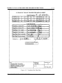
The data sheet, shown in Figure 4-13, provides all of the serial numbers (S/N) and length data
pertaining to the meter’s original transducer assembly components. This data sheet can be obtained
by contacting Daniel Measurement Services at 713-827-6314.
• Prior to replacing the transducers, it is imperative that each of the transducer pairs be
installed in the correct location (i.e. A1, A2, etc) since changing the transducers, or any
components of the assembly, will impact the chord length. Mark the location on the
Transducer Pair Data Sheet (see Figure 4-13, the data sheet included in the upgrade kit for
new transducers), and also mark the location on the side of the transducer with the marker
pen (see Figure 4-5 for these components). This will prevent any confusion when the
transducers are installed and the meter’s configuration parameters are updated. The values
on the Transducer Pair Data Sheet relate to a unique pair of transducers. Do not mix
transducers from different pairs.
• It is recommended that only one pair (i.e. A1 & A2 or B1 & B2 etc.) of transducer assemblies
be removed at a time to avoid installing the transducer assemblies in the wrong position.
When this isn’t practical, before removing the transducer assemblies from the mount, ensure
that the transducer location (i.e. A1, A2, etc) is marked on one of the flats of the 1¼" holder
head (see Figure 4-4). Ensure the marking will not be accidentally erased during removal
of the old transducer.
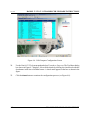
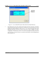
• When the transducers are replaced, the applicable chord parameters must be updated. Use
the Transducer Swap-out Wizard in Daniel CUI (see Figures 4-6 through 4-9 for screen shots
of this wizard). This procedure requires writing changes to the meter. If the write-protection
jumper (JP2 on the DFI Board) is installed, it will need to be removed.

DANIEL T-2 TO T-11 TRANSDUCER UPGRADE INSTRUCTIONS DEC 2005
TRANSDUCER UPGRADE PROCEDURE 4-1
4.0 TRANSDUCER UPGRADE PROCEDURE
1. Prior to starting the transducer replacements, a minimum of a two-minute maintenance log
file should be collected.
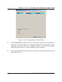
2. Use the Edit/Compare Configuration Wizard to read the configuration from the meter.
3. Name the configuration file clearly to indicate it is before the transducer upgrade (by editing
the Daniel CUI automated file name shown in the Edit/Compare Configuration Wizard
screen (e.g. "Meter Name, Meter config, T-2 Transducers, 3-3-2005 4-48-58 PM.cfg").
4. When the upgrade procedure is complete and all of transducers are replaced and the data
updated, save the configuration file named "Meter Name, Meter config, T-11 Transducers,
3-3-2005 5-10-07 PM.cfg".
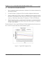
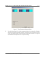
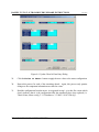
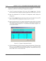
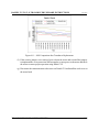
The chart in Figure 4-1 shows a typical SOS (Speed of Sound) comparison chart for a meter at zero
flow. It can be seen on the Charts sheet in the maintenance log file.
Figure 4-1. Typical SOS Comparison Chart

DEC 2005 DANIEL T-2 TO T-11 TRANSDUCER UPGRADE INSTRUCTIONS
TRANSDUCER UPGRADE PROCEDURE4-2
SERIOUS PERSONAL INJURY OR DEATH POSSIBLE
If the meter cannot be depressurized, use the Ultrasonic Extraction tool to remove and
re-install the transducer assemblies.
Failure to follow the extractor tool manual procedures may result in serious personal injury or
death and may cause equipment damage.
If the meter cannot be depressurized, refer to the Daniel Ultrasonic Extractor Tool Operation
Manual (P/N 3-9000-729). The most recent copy of this manual may be downloaded from the Daniel
website (http://www.emersonprocess.com/daniel/). Follow the steps in Section 4 of the Ultrasonic
Extractor Tool Operation Manual for removing the transducers under pressure, instead of steps 5
through 8 below.
5. Depressurize the meter and isolate the meter run piping, and vent the gas to atmosphere.
Verify that the pressure is 0 psig before proceeding.
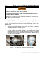
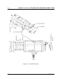
6. Prior to removing the holder cover, put an alignment mark on the edges of both the holder
cover and the mount cover using the marker pen. This will help facilitate rotational
alignment during the re-assembly. Remove the holder cover (see Figure 4-2) by completely
loosening the two captive screws. Gently pull back the cover and cable, unplug the cable and
expose the mount cover assembly.
Figure 4-2. Side and End View of M-Mount Transducer Assembly

DANIEL T-2 TO T-11 TRANSDUCER UPGRADE INSTRUCTIONS DEC 2005
TRANSDUCER UPGRADE PROCEDURE 4-3
7. After labeling the mount cover location (A1, A2, etc.), loosen the two screws in the mount
cover as shown in Figure 4-3, below. Note that these two screws may or may not be captive.
If they are not captive, remove them carefully. With the two screws fully unscrewed, pull the
mount cover off of the hex head of the holder exposing the mount and holder assembly.
Figure 4-3. Mount Cover
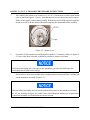
8. Loosen the T-Slot transducer assembly holder with the 1¼" wrench or socket (see Figure 4-
4). Once it has been loosened, it should be possible to unscrew it by hand.
Unless the meter/piping has a vent open to the atmosphere, pressure may build up in the
meter/piping due to minor valve leakage.
Ensure there is no pressure buildup before completely unscrewing the holder. Carefully pull
out the transducer assembly (Figure 4-5).
If the hex head of the holder does not clearly indicate the location of the transducer assembly
(A1, A2, etc. as shown in Figure 4-4), mark it now with a Sharpie® marker pen (or equivalent)
to ensure the assembly is re-installed in the correct location.

DEC 2005 DANIEL T-2 TO T-11 TRANSDUCER UPGRADE INSTRUCTIONS
TRANSDUCER UPGRADE PROCEDURE4-4
Figure 4-4. Mount and T-Slot Transducer Assembly
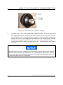
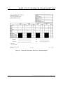
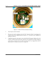
9. Loosen the three 6-32 set screws that hold the transducer in place. The screws do not need
to be completely removed. On some of the older assemblies, Loc-Tite™ is used on the set
screws. If the set screw is very tight and does not appear to come out without damage to the
wrench or the set screw, try heating the area around the set screw with a heat gun. Often this
will help in releasing the bond and allows the screw to be removed without damage. Use
caution when heating the stalk area around the set screw. Overheating may cause damage
to the stalk.
If the inside of the set screw is stripped due to Allen wrench slippage and the screws cannot be
extracted, it may be necessary to loosen the set screws by holding the stalk in place. If this is
the case, a new stalk must be obtained and installed. The length of the replacement stalk will
be required to update the meter configuration.

DANIEL T-2 TO T-11 TRANSDUCER UPGRADE INSTRUCTIONS DEC 2005
TRANSDUCER UPGRADE PROCEDURE 4-5
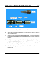
Figure 4-5. Transducer Assembly
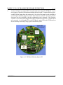
10. After all three set screws have been loosened, as shown in Figure 4-5, remove the transducer
from the holder assembly.
11. Replace the O-rings and back-up rings on the transducer holder. It is recommended that they
be replaced while the transducer is removed from the holder/stalk to prevent damage to the
transducer.
12. Install the new transducer designated for that location. The parts are keyed so that they only
fit together one way. Tighten the three set screws equally to lock the new transducer into
place. DO NOT OVER TIGHTEN. Confirm the serial number of the transducer, and
installation location (i.e. A1, A2, etc.) previously marked on the Transducer Pair Data Sheet.
See annotated data sheet in Figure 4-13.
13. Clean the transducer ports, mounts, and T-Slot transducer before re-installing the new
transducer pair.

DEC 2005 DANIEL T-2 TO T-11 TRANSDUCER UPGRADE INSTRUCTIONS
TRANSDUCER UPGRADE PROCEDURE4-6
14. Lubricate the O-rings/back-up rings with a small amount of Dow Corning III silicon grease
®
(or equivalent).
15. Apply a small amount of Nickel anti-seize compound (P/N 3-9960-134 or equivalent) to the
threads on the transducer holder.
SERIOUS PERSONAL INJURY OR DEATH POSSIBLE
If the extractor tool was used to remove the transducer assemblies while under pressure,
use the tool to re-install the transducers. Follow the procedures in Section 5 of the
Ultrasonic Extractor Tool manual, instead of step 16 in this procedure. Once the
transducer has been installed, continue with step 17.
Failure to follow the extractor tool manual procedures may result in serious personal injury or
death and may cause equipment damage.
16. Carefully insert the assembly into the assigned transducer port. With the 1¼" wrench or
socket, tighten the holder in the mount, until it is snug and securely seated (specification
torque = 35 lb-ft). DO NOT OVER TIGHTEN.
17. Repeat the entire procedure for each of the remaining transducer pairs being replaced.
18. With the system sealed, apply minimal pressure to the meter. Using soapy water, or other
leak check method, check for leakage around the transducer mounts and holder. Fix any leak
before proceeding. If no leaks are detected, fully pressurize the meter to line conditions (or
at least 200 psi).
19. Replace the mount covers in their original locations. Position them so the cover slips over
the 1 ¼” hex head screw of the transducer holder and the screw slots on the side allow access
to the screw-hole in the transducer mount underneath. Observe the alignment marks applied
in step 6. The metal locking plate on the surface of the cover can be rotated approximately
¼" to engage the plate on the 1¼" hex head of the holder. While holding the body of the
cover, rotate the locking plate by pushing on the tabs with the thumb and finger while
pushing down (see Figure 4-3). Once the locking plate is engaged and the cover is fully
seated on the mount, install the two screws that attach the cover to the mount.
Page is loading ...
Page is loading ...
Page is loading ...
Page is loading ...
Page is loading ...
Page is loading ...
Page is loading ...
Page is loading ...
Page is loading ...
Page is loading ...
Page is loading ...
Page is loading ...
Page is loading ...
Page is loading ...
Page is loading ...
Page is loading ...
Page is loading ...
Page is loading ...
Page is loading ...
Page is loading ...
Page is loading ...
Page is loading ...
Page is loading ...
Page is loading ...
-
 1
1
-
 2
2
-
 3
3
-
 4
4
-
 5
5
-
 6
6
-
 7
7
-
 8
8
-
 9
9
-
 10
10
-
 11
11
-
 12
12
-
 13
13
-
 14
14
-
 15
15
-
 16
16
-
 17
17
-
 18
18
-
 19
19
-
 20
20
-
 21
21
-
 22
22
-
 23
23
-
 24
24
-
 25
25
-
 26
26
-
 27
27
-
 28
28
-
 29
29
-
 30
30
-
 31
31
-
 32
32
-
 33
33
-
 34
34
-
 35
35
-
 36
36
-
 37
37
-
 38
38
-
 39
39
-
 40
40
-
 41
41
-
 42
42
-
 43
43
-
 44
44


Daniel Ultrasonic Flow Meters-T-2 to T-11 Transducer Upgrade Operating instructions
- Type
- Operating instructions
Ask a question and I''ll find the answer in the document
Finding information in a document is now easier with AI
Related papers
-
Emerson Process Management 4.21 User manual
-
Daniel Control Valves - Model 700A Series Sizes 2 to 12 inch User manual
-
-
-
-
-
-
-
-
Emerson 3-9000-744 User manual
Other documents
-
Garmin Nexus Owner's manual
-
-
 Remote Automation Solutions ROC300/FB407: Ultrasonic Serial I/O Interface Owner's manual
-
Emerson 3412 User manual
-
 Underwriters Laboratories S600 Series User manual
-
-
AMS General Standard Conditions of Purchase Epro GmbH Owner's manual
-
Audiovox MMD85A Warranty Card
-
Elster UFM Series 6 Operating instructions

