Page is loading ...

OPERATION MANUAL [English]
1st Edition (Revised 4)
DIGITAL CINEMATOGRAPHY CAMERA
F35

2
To reduce the risk of fire or electric shock,
do not expose this apparatus to rain or
moisture.
To avoid electrical shock, do not open the
cabinet. Refer servicing to qualified
personnel only.
For the customers in the U.S.A.
This equipment has been tested and found to comply with the
limits for a Class A digital device, pursuant to Part 15 of the
FCC Rules. These limits are designed to provide reasonable
protection against harmful interference when the equipment is
operated in a commercial environment. This equipment
generates, uses, and can radiate radio frequency energy and,
if not installed and used in accordance with the instruction
manual, may cause harmful interference to radio
communications. Operation of this equipment in a residential
area is likely to cause harmful interference in which case the
user will be required to correct the interference at his own
expense.
You are cautioned that any changes or modifications not
expressly approved in this manual could void your authority to
operate this equipment.
All interface cables used to connect peripherals must be
shielded in order to comply with the limits for a digital device
pursuant to Subpart B of Part 15 of FCC Rules.
For the customers in Europe
This product with the CE marking complies with the EMC
Directive issued by the Commission of the European
Community.
Compliance with this directive implies conformity to the
following European standards:
• EN55103-1: Electromagnetic Interference (Emission)
• EN55103-2: Electromagnetic Susceptibility (Immunity)
This product is intended for use in the following
Electromagnetic Environments: E1 (residential), E2
(commercial and light industrial), E3 (urban outdoors), E4
(controlled EMC environment, ex. TV studio).
The manufacturer of this product is Sony Corporation, 1-7-1
Konan, Minato-ku, Tokyo, Japan.
The Authorized Representative for EMC and product safety is
Sony Deutschland GmbH, Hedelfinger Strasse 61, 70327
Stuttgart, Germany. For any service or guarantee matters
please refer to the addresses given in separate service or
guarantee documents.
For the State of California, USA only
Perchlorate Material - special handling may apply, See
www.dtsc.ca.gov/hazardouswaste/perchlorate
Perchlorate Material : Lithium battery contains perchlorate.
For the customers in Taiwan only
WARNING

3
Afin de réduire les risques d’incendie ou
d’électrocution, ne pas exposer cet
appareil à la pluie ou à l’humidité.
Afin d’écarter tout risque d’électrocution,
garder le coffret fermé. Ne confier
l’entretien de l’appareil qu’à un personnel
qualifié.
Pour les clients en Europe
Ce produit portant la marque CE est conforme à la Directive
sur la compatibilité électromagnétique (EMC) émise par la
Commission de la Communauté européenne.
La conformité à cette directive implique la conformité aux
normes européennes suivantes :
• EN55103-1 : Interférences électromagnétiques (émission)
• EN55103-2 : Sensibilité électromagnétique (immunité)
Ce produit est prévu pour être utilisé dans les environnements
électromagnétiques suivants : E1 (résidentiel), E2
(commercial et industrie légère), E3 (urbain extérieur) et E4
(environnement EMC contrôlé, ex. studio de télévision).
Le fabricant de ce produit est Sony Corporation, 1-7-1 Konan,
Minato-ku, Tokyo, Japon.
Le représentant autorisé pour EMC et la sécurité des produits
est Sony Deutschland GmbH, Hedelfinger Strasse 61, 70327
Stuttgart, Allemagne. Pour toute question concernant le
service ou lagarantie, veuillez consulter les adresses
indiquées dans les documents de service ou de garantie
séparés.
Um die Gefahr von Bränden oder
elektrischen Schlägen zu verringern, darf
dieses Gerät nicht Regen oder Feuchtigkeit
ausgesetzt werden.
Um einen elektrischen Schlag zu
vermeiden, darf das Gehäuse nicht
geöffnet werden. Überlassen Sie
Wartungsarbeiten stets nur qualifiziertem
Fachpersonal.
Für Kunden in Europa
Dieses Produkt besitzt die CE-Kennzeichnung und erfüllt die
EMV-Richtlinie der EG-Kommission.
Angewandte Normen:
• EN55103-1: Elektromagnetische Verträglichkeit
(Störaussendung)
• EN55103-2: Elektromagnetische Verträglichkeit
(Störfestigkeit), für die folgenden elektromagnetischen
Umgebungen: E1 (Wohnbereich), E2 (kommerzieller und in
beschränktem Maße industrieller Bereich), E3 (Stadtbereich
im Freien) und E4 (kontrollierter EMV-Bereich, z.B.
Fernsehstudio).
Der Hersteller dieses Produkts ist Sony Corporation, 1-7-1
Konan, Minato-ku, Tokyo, Japan.
Der autorisierte Repräsentant für EMV und Produktsicherheit
ist Sony Deutschland GmbH, Hedelfinger Strasse 61, 70327
Stuttgart, Deutschland. Bei jeglichen Angelegenheiten in
Bezug auf Kundendienst oder Garantie wenden Sie sich bitte
an die in den separaten Kundendienst- oder
Garantiedokumenten aufgeführten Anschriften.
AVERTISSEMENT WARNUNG

4
Table of Contents
Table of Contents
Chapter 1 Overview
1-1 Features .......................................................................... 8
1-2 Example of System Configuration ............................. 10
1-2-1 SRW-1 Docking System ................................................11
1-2-2 Optical Fiber System Using the CA-F101 .....................11
1-3 Locations and Functions of Parts .............................. 12
1-3-1 Camera Head ..................................................................12
1-3-2 Assistant Panel (Supplied) .............................................17
1-3-3 Interface Box (Supplied) ................................................17
Chapter 2 Installation and Preparations
2-1 Mounting the Interface Box ......................................... 19
2-2 Mounting the SRW-1 Recorder ................................... 21
2-3 Mounting the CA-F101 and Optical Connection ....... 22
2-4 Attaching a Lens .......................................................... 23
2-5 Attaching a Viewfinder ................................................ 24
2-6 Mounting the Camera to a Tripod ............................... 25
2-7 Attaching/Detaching Handles ..................................... 26
2-7-1 L Handle ........................................................................26
2-7-2 Center Handle (Supplied) ..............................................26
2-8 Preparing the Power Supply ....................................... 27
2-9 Setting the Built-in Clock ............................................ 29
Chapter 3 Basic Adjustments and Settings
3-1 Selection of the Basic Operation Modes ................... 30
3-1-1 Overview of the Basic Operation Modes .......................30
3-1-2 Switching of the Basic Operation Modes ......................30
3-2 Basic Settings with the Subdisplay ........................... 32
3-2-1 Basic Operation of the Subdisplay .................................32
3-2-2 Shutter Settings ..............................................................33
3-2-3 RAMP Operation ...........................................................35
3-2-4 Selection of Video Formats ...........................................35
3-2-5 Retrieving the ND Offset ...............................................36
3-2-6 Selection of the Gain, Color Temperature, and White
Balance Memory ............................................................36

5
Table of Contents
3-2-7 Selection of a Lens File ..................................................37
3-2-8 Confirmation of the Time Code and Tape Remaining ...38
3-2-9 Confirmation of the Power Voltage and Selection of Fan
Operation Mode .............................................................38
3-2-10 ON/OFF of the Character Indication ............................39
3-2-11 Allocation of Functions to the Assignable Buttons and
Switch ............................................................................39
3-2-12 Brightness Adjustment of the Subdisplay ....................40
3-2-13 Selection of Gamma Tables .........................................40
3-2-14 Selection of Color Spaces ............................................40
3-2-15 Checking the Optical Levels ........................................40
3-2-16 Limiting Pages that are Displayed on the Subdisplay ..41
3-3 Black Balance Adjustment ...........................................42
3-4 White Balance Adjustment (in Custom mode) ...........43
3-5 Setting the Camera Outputs ........................................44
3-5-1 Selecting a Video Output Signal for Each Connector ....44
3-5-2 Setting the Monitor Picture ............................................45
3-5-3 Outputting Color Bars ....................................................47
3-6 Viewing and Setting the Viewfinder Displays ............48
3-6-1 Viewing the Basic Status Indications .............................48
3-6-2 Viewing the LENS (Lens Information) Display ............50
3-6-3 Viewing the ABNORMAL <!> Display ........................50
3-6-4 Viewing the FUNCTION (Format/Switch Function)
Display ...........................................................................51
3-6-5 Setting the Marker Indications .......................................51
3-6-6 Adjusting the Viewfinder Details ...................................52
3-6-7 Setting the Zebra Indication ...........................................52
3-6-8 Setting the Cursor Indication .........................................53
3-6-9 Checking the Power Voltage ..........................................54
3-7 Detailed Settings of the Switch Functions .................54
3-8 Setting the Gain ............................................................55
3-9 Detailed Shutter Settings .............................................56
3-10 Resuming the Standard Conditions ..........................57
3-11 Selecting the Gamma .................................................58
3-11-1 Using the Standard Gamma .........................................58
3-11-2 Using Hyper Gamma ....................................................58
3-11-3 Using the S-LOG ..........................................................60
3-11-4 Using the User Gamma ................................................60
3-12 Inverting the Camera Picture .....................................61
3-13 Detailed Setting of the Video Format ........................61

6
Table of Contents
Chapter 4 Menu Configuration and Detailed Settings
4-1 Menu Configuration ..................................................... 63
4-2 Basic Menu Operations ............................................... 64
4-2-1 Displaying Setting Pages ...............................................65
4-2-2 Setting the Menu Items ..................................................66
4-2-3 Menu Operation via a Web Browser .............................66
4-3 Menu List ...................................................................... 68
4-3-1 OPERATION Menu ......................................................68
4-3-2 PAINT Menu .................................................................77
4-3-3 MAINTENANCE Menu ................................................84
4-3-4 NETWORK Menu .........................................................90
4-3-5 FILE Menu .....................................................................91
4-3-6 DIAGNOSIS Menu ........................................................95
4-4 Editing the USER Menu ............................................... 96
Chapter 5 Storage and Retrieval of User Setting Data
5-1 File Configuration ........................................................ 99
5-2 List of Items Stored in Files ...................................... 101
5-3 File Operations ........................................................... 103
5-3-1 Using a “Memory Stick” ..............................................103
5-3-2 Storage and Retrieval of the Operator File ..................104
5-3-3 Registration and Retrieval of the Lens Files ................104
5-3-4 Storage and Retrieval of the Scene Files .....................105
5-3-5 Storage and Retrieval of the Reference File ................106
5-3-6 Reading of the User Gamma ........................................106
5-3-7 Reading of the User MLUT .........................................106
5-3-8 Storage of the OHB File ..............................................107
5-3-9 Resetting to the Initial Settings ....................................107
Appendixes
Using the RM-B750 ........................................................... 109
Connection ..............................................................................109
Operating the Menu of This Camera ......................................109
Monitoring the Camera Image ................................................110
Using the MSU-900/950 .................................................... 110
Connections ............................................................................110
Parameter Settings ..................................................................111
Using the ARRI Remote Control ...................................... 113
About Metadata ................................................................. 114

7
Table of Contents
Warning/Error Messages ..................................................126
Precautions ........................................................................127
About a “Memory Stick” ...................................................128
Specifications ....................................................................130
Camera Head ...........................................................................130
Interface Box (Supplied) .........................................................132
Optional Accessories ..............................................................132
Connector Pin Assignments .............................................133
Color Space According to the COLOR SPACE Settings 136
Lip Sync Compensation ....................................................137
Index ...................................................................................138

8
Features
Chapter 1 Overview
Chapter
1
Overview
1-1 Features
The F35 is a 1CCD digital cinematography camera
equipped with Super 35-mm type IT progressive CCD
array with a total of 6,600,000 picture elements (effective
pixel count of 1920 [H] × 1080 [V] RGB).
The camera is incorporated with newly developed imagers
and a digital signal-processing LSI that yield images of a
high quality for cinematic, commercial, and dramatic
production applications. The camera also supports the
features of a “production camera” up to details in its shape,
button and indicator layout, and materials of the parts.
Superior Picture Quality and High
Performance
Super 35-mm type CCD and PL Mount
With the F35’s Super 35-mm-type CCD imagers and PL
Mount, most movie lenses designed for conventional 35-
mm film cameras can be mounted without a converter.
Wide dynamic range and high-quality digital
pictures
With its newly developed imagers, 14-bit A/D converter,
and unique digital LSI, the camera achieves significant
extension of the dynamic range and picture quality of
optimal grade, minimizing noises.
RGB 4:4:4 image capturing
The RGB 4:4:4 image-capturing capability, having high
affinity with computer graphics, yields significant results,
especially in chroma-keying and color-correction
processes where highly exacting special-effects sequences
and elaborate finishes are required in demanding movie-
making, commercial, and television applications.
Variable-speed recording
When used with a Sony SRW-1 HD Portable Digital
Recorder, the number of frames per second (FPS) for
shooting/recording is selectable in single-frame
increments. This allows users to create slow- or fast-
motion effects equivalent to those obtained by
“overcranking” or “undercranking” a cinematic film
camera.
Frame-rate settings for this function are variable from 1 to
50 FPS.
Multiple frame formats
The camera covers the1080 formats of different types to
allow it to be used for high-end content creation, including
commercial and broadcasting program production as well
as movie making.
• Progressive mode: 1080/23.98P, 1080/24P, 1080/25P,
1080/29.97P, 1080/50P
• Progressive mode (variable): 1080/S23.98P, 1080/S24P,
1080/S29.97P, 1080/S30P, 1080/S50P, 1080/S59.94P
(MAX50), 1080/S60P (MAX50)
• Interlace mode: 1080/50i, 1080/59.94i
Imaging characteristics with wide color space
Sony’s unique technology allows the camera to capture
images in natural-looking colors closer to those of the
actual scene than with conventional cameras.
S-LOG and Hyper gammas
The camera is equipped with S-LOG gammas that enable
shooting styles equivalent to a film camera and Hyper
gammas that achieve smooth gradation reproduction,
thanks to the wide dynamic range.
User Gamma
The camera allows you to customize gamma curves
according to your creative needs, using the supplied
CvpFileEditor
1)
application software.
1) You can download the latest version of the software from the “eCSite,” the
site for downloading business and professional software from Sony
Corporation.
Design and Shape
New compact design
For a high level of mobility in consideration of various
shooting situations, such as inside a car, the camera is
housed in as compact a body as possible. In addition,
buttons and indicators are laid out to provide a familiar and
intuitive user interface to users of conventional cinema
film cameras.

9
Features
Chapter 1 Overview
Dockable system of the SRW-1 HD Portable
Digital Recorder
A dockable interface system is employed to conform to
versatile shooting conditions and on-site demands.
The SRW-1
1)
can be docked directly on the top or rear of
the camera, as required for shooting conditions.
The camera and SRW-1 recorder can also be tethered via
cables to take advantage of the compactness of the camera
for higher mobility.
1) The firmware of the SRW-1 may be required to be updated for use with the
camera. For details, consult your local Sony representative.
Compatible with film-camera accessories
The F35 is designed to be compatible with a variety of
film-camera accessories, giving users a broad array of
choices. These include ARRIFLEX-made bridge plates,
matte boxes, follow focus units, lens focus/zoom/iris servo
control units, and more. These film-camera accessories
can be attached to the F35 without modification, enabling
users who principally work with film to fully utilize their
assets.
Having one 12 V DC output connector and another 24 V
DC
1)
output connector, the F35 can supply power to such
compatible accessories attached to it through these
connectors.
1) To feed 24 V DC power in synchronization with the power switch of the
camera, an independent power supply of 24V DC is required in addition to
the 12 V power.
Assignable switches
Functions frequently used in the field, such as optical filter
switching, can be assigned to three push buttons and one
switch located on the side panel of the camera, allowing
the operator to make rapid changes when working in the
field.
Saving/retrieving settings with a “Memory
Stick”
1)
Using a “Memory Stick,” you can save menu settings for
particular shooting conditions for retrieval when required.
1) Memory Stick and are trademarks of Sony
Corporation.
Operational Versatility
Two operation modes: Cine and Custom
The F35 offers two operation modes; “Cine Mode” for
movie-making applications, where image tone is normally
adjusted in post production, and “Custom Mode,” which is
suitable for users who wish to fine-tune camera parameters
to produce their desired look in on-set grading.
Shutter control
When using the electronic shutter, the setting indication
can be switched between the shutter angle (degree) and
shutter speed (second).
Monitor output selection
For monitor outputs, the user can select flexibly whether to
mix character information and markers, whether to apply
alternative monitor LUT (look-up table) other than that
applied to the camera signal, or how to mix the playback
picture.
Image inversion function
The image inversion function, field-proven in Sony’s F23
digital cinematography camera and HDW-F900R HD
digital camcorder, is included among the standard
functions with the F35.
The delay of video relative to audio may vary according to
the ON/OFF setting of this function (see page 137).
Other Features
Assistant panel
The supplied assistant panel has an identical button and
indicator layout to that of the on-camera control panel and
provides intuitive remote control of basic camera
operations, such as control of frame rate (fps), shutter
(indication in angles enabled), gain, color temperature
(switching between Tungsten and Daylight enabled),
timecode/tape remaining check, character indications, and
function assignment to the assignable buttons.
Down-conversion output
The down-converter built into the camera as standard
equipment enables camera pictures as well as VTR
playback pictures to be monitored using a conventional SD
monitor.
Twin-viewfinder operation
Two viewfinders can be attached to the F35 for
simultaneous monitoring with different settings of
character information and marker indications.
When using an HDVF-C30WR, color space adjustment for
the viewfinder is enabled.
Lens hot shoes
The camera is equipped with hot shoes for the ARRI
1)
LDS (Lens Data System) and Cooke
2)
/i Intelligent
Electronic Lens System. When a lens with corresponding
characteristics is mounted, information regarding the lens,
such as the type, serial number, iris setting, and focus
position, may be available for on-screen displays and
metadata recording.
1) ARRI Group
2) Cooke Optics Limited

10
Example of System Configuration
Chapter 1 Overview
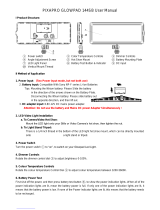
1-2 Example of System Configuration
The diagram below shows a system configuration example
to use of this camera.
In this manual, an optional HDVF-C35W HD Electronic
Viewfinder is used to instruct how to operate the unit.
For more information about the fittings, connections, or
use of additional equipment and accessories, see “Chapter
2 Installation and Preparations” as well as the operation
manuals for the connected equipment.
When using the SRW-1, CA-F101, or a control device,
such as an RM-B750, in combination with this camera,
you must check each of their versions.
Consult a Sony representative for information about these
versions.
Note
Viewfinder-related equipment
Name / Purpose Magnification Part No.
Fog-proof filter — 1-547-341-11
Lens assembly –2.8 D to +2.0 D A-8262-537-A
Lens assembly –3.6 D to –0.8 D A-8262-538-A
Lens assembly –3.6 D to +0.4 D A-8267-737-A
Lens assembly
(3 × magnification)
–2.4 D to +0.5 D A-8314-798-A
L
O
C
K
Video recorder and related device
SRW-1 HD Portable Digital Recorder
CA-F101 Optical Fiber Camera Adapter
Remote control devices
RM-B750 Remote Control Unit
MSU-900/950 Master Setup Unit
Data storage media
“Memory Stick PRO”
“Memory Stick PRO Duo”
Products for tripod mounting
Name Model name
Bridge Plate BP-5 (ARRIFLEX made)
Shoulder Set S-1 (ARRIFLEX made)
F35
Product Configuration
Center handle
L handle
Assistant panel
Interface box
Camera head
Products for battery operation
Product for AC power supply
Product Model name
Battery Pack BP-GL95
Battery Adaptor BKP-L551
Product Model name
AC Adaptor AC-DN2B
Riser plate
Viewfinders HDVF-20A HD Electronic Viewfinder
HDVF-C30WR HD Electronic Viewfinder
HDVF-C35W HD Electronic Viewfinder
Note: When the AC-DN2B is used, turning on the
camera with an RM-B750 Remote Control Unit
connected may make the RM-B750 inoperable.
To reenable the RM-B750, disconnect and
reconnect the remote control cable maintaining
the power-on status.

11
Example of System Configuration
Chapter 1 Overview
1-2-1 SRW-1 Docking System
An SRW-1 recorder can be mounted either on the top or rear of the camera head.
Power can also be supplied to the recorder via the DC IN connector (LEMO 8-pin) of the camera head.
Upper docking
The interface box can be attached to the rear.
Rear docking
The interface box can be attached to the top.
1-2-2 Optical Fiber System Using the CA-F101
Attaching an optional CA-F101 Optical Fiber Camera
Adapter to the camera enables signal transmission and
interface between the camera and the SRW-1 HD Portable
Digital Recorder/SRPC-1 HD Video Processor with the
HKSR-101 Optical Interface Unit via a hybrid optical
camera cable.
For this system, independent power supply to both the
camera and the recorder is required.
Attaching the CA-F101 to the top and the interface unit to
the rear is also allowed.
For details, refer to the Operation Manual of the CA-F101.
HDVF-C35W
Interface box
(supplied with the
camera)
DC 12 V power
SRW-1
HDVF-C35W
Interface box
(supplied with the
camera)
DC 12 V power
SRW-1
60
5.6
8
11
16
CL
2.8
2
1.6
T
ff
4
30
20
15
12
10
8
7
6
5.6
5
4.6
HDVF-C35W
Hybrid optical camera cable
DC 12 V power
DC 12 V power
SRW-1
SRPC-1 +
HKSR-101
Interface box (supplied
with the camera)
CA-F101

12
Locations and Functions of Parts
Chapter 1 Overview
1-3 Locations and Functions of Parts
1-3-1 Camera Head
Front panel
a VF1 (viewfinder 1) connector (20-pin)
Connect a viewfinder (optional).
b CONTROL PANEL connector
Connect with the CAMERA connector of the supplied
assistant panel (page 17).
c Accessory receptacles
Using these screw holes in combination with the accessory
pockets (page 13) on the left side, you can fix a certain
accessory to the left side of the camera.
d VF2 (viewfinder 2) connector (20-pin)
Connect a second viewfinder (optional), e.g. for an
assistant.
When two viewfinders are connected at the same time (via
the VF1 and VF2 connectors), the HDVF-C950W cannot
be used because of a limitation of current capacity.
e LENS connector (12-pin)
To use a lens control unit (optional), connect it to this
connector. You can control the iris of the lens through this
connector.
Do not connect a device whose maximum rated current is
500 mA or higher to the LENS connector.
f Viewfinder shoe
Attach an optional viewfinder.
The height of the attaching position can be adjusted.
For details, see “2-5 Attaching a Viewfinder” (page 24).
g Flange focal length adjustment screw
You can adjust the flange focal length with the screw
behind the cover.
For details, see “Adjusting the flange focal length” (page
23).
h Lens fixing lever
Turn the lever clockwise to secure the lens in the lens
mount. To remove the lens, turn the lever
counterclockwise.
For details, see “2-4 Attaching a Lens” (page 23).
i Lens mount cap
Cover the lens mount with this cap when a lens is not
attached. The cover may be removed by rotating the lens
fixing lever counterclockwise.
j Shutter emergency opening screw
You can forcibly open the shutter in an emergency.
For details, see “To forcibly open the shutter” on page
127.
CONTROL
PA NE L
VF2
LENS
VF1
b CONTROL PANEL connector
c Accessory receptacles
d VF2 connector
f Viewfinder shoe
Lens mount
i Lens mount cap
a VF1 connector
h Lens fixing lever
g Flange focal length adjustment screw
j Shutter emergency open screw
e LENS connector
Ventilation holes (intake)
Ventilation holes (intake)
Note
Note

13
Locations and Functions of Parts
Chapter 1 Overview
Left panel
a Level vial
Used as a reference to check that the camera stands
horizontally. It can be fine-adjusted when required.
If fine-adjustment is required, remove the cover and adjust
it by rotating the three slotted-head screws.
b L handle
The L handle is attached to the top of the camera head at
the factory.
It has three screw holes (
3
/
8
") for accessories on the upper
side. The assistant panel (page 17) can be mounted on the
outside of the handle by attaching the supplied assistant
panel hanger.
c Accessory pockets
Using these accessory pockets in combination with the
accessory receptacles (page 12) on the front panel, you can
fix a certain accessory to the left side of the camera.
d DC IN connector (LEMO 8-pin)
Power is supplied by using a specified power cord.
e Power indicators
Either of the indicators lights according to the voltage of
the power being supplied.
f CAM POWER switch
CA: The camera is turned on using the power being
supplied via the interface box (page 17) or CA-F101
(page 22) mounted on the rear.
Note that power is not supplied to an SRW-1
simultaneously mounted on the top via the interface
box mounted on the rear. To supply power to the SRW-
1, use power supply via the DC IN connector (LEMO
8-pin) of the camera head.
OFF: The power is cut off.
ON: The camera is turned on using the power being
supplied from the DC IN connector (LEMO 8-pin) of
the camera head.
If you move the switch setting from ON to CA in one
stroke, the power may not be cut off. To turn off the power,
be sure to set the switch to the OFF position.
g EXT I/O (external control) connector (5-pin)
For control via RS-232C.
c Accessory pockets
d DC IN connector
e Power indicators
f CAM POWER switch
g EXT I/O connector
h (network) connector
i DC OUT 12V connector
j DC OUT 24V connector
b L handle
a Level vial
k Measure hook/focus
reference mark
Note

14
Locations and Functions of Parts
Chapter 1 Overview
h (network) connector (RJ-45 type, 10BASE-T,
100BASE-TX)
For control from the MSU-900/950 Master Setup Unit, etc.
via a network cable.
The necessary settings are made using the NETWORK
menu displayed on the viewfinder or monitor screen.
For safety, do not connect the connector for peripheral
device wiring that might have excessive voltage to this
port. Follow the instructions for this port.
Par mesure de sécurité, ne raccordez pas le connecteur
pour le câblage de périphériques pouvant avoir une tension
excessive à ce port. Suivez les instructions pour ce port.
Aus Sicherheitsgründen nicht mit einem Peripheriegerät-
Anschluss verbinden, der zu starke Spannung für diese
Buchse haben könnte. Folgen Sie den Anweisungen für
diese Buchse.
i DC OUT 12V (DC 12V power output) connector
DC 12V power can be fed to an accessory.
j DC OUT 24V (DC 24V power output) connector
DC 24 V power can be fed to an accessory.
k Measure hook/focus reference mark
Use as reference for focusing. The same reference mark is
also provided at the right of the riser plate (page 15).
For actual measurement of the distance from a subject, you
can fix the end of a tape measure to the hook.
Right panel
a Assignable buttons 1, 2, 3
You can assign various functions to these buttons, using
the subdisplay on the left panel or on the assistant panel or
the menu displayed on the viewfinder or monitor screen.
No function is assigned at the factory.
For details, see “3-2-11 Allocation of Functions to the
Assignable Buttons and Switch” (page 39) and “3-7
Detailed Settings of the Switch Functions” (page 54).
b LOCK switch
To disable operations on the panel.
You can make a setting to allow the RUN button to be
activated even when the LOCK switch is set to ON on the
<SUBDISPLAY 2> page on the USER (OPERATION)
menu.
c RUN button and indicator
To start/stop recording on the SRW-1 HD Portable Digital
Recorder docked on or optically connected to the camera.
The indicator is lit while the recorder is in Recording
mode.
The indicator flashes as a warning in some cases.
While the SRW-1 is operating in REC REVIEW, PLAY ,
F.FWD, or REW mode, the RUN button becomes invalid
to prevent overwriting.
For details on warning indication, see “Warning/Error
Messages” (page 126).
CAUTION
ATTENTION
VORSICHT
123
b LOCK switch
c RUN button and indicator
d 4/AUTO BLK BAL switch
i Memory stick section
f Accessory clamp lever
g Lock release knob
a Assignable buttons 1, 2, 3
j Focus reference mark
k Tripod receptacles (bottom)
e Safety release tab
h Accessory mount lever
Display/menu operation block
(page 15)
Riser plate
Ventilation holes (intake)

15
Locations and Functions of Parts
Chapter 1 Overview
The firmware of the SRW-1 may be required to be updated
for use with this camera. For details, consult your local
Sony representative.
d Assignable 4/AUTO BLK BAL (auto black balance)
switch
Push the switch downward to the AUTO BLK BAL side to
start the auto black balance adjustment.
The function activated by pressing the switch upward to
the 4 side can be selected using the subdisplay on the left
panel or on the assistant panel or the menu displayed on the
viewfinder or monitor screen.
For details, see “3-2-11 Allocation of Functions to the
Assignable Buttons and Switch” (page 39) and “3-7
Detailed Settings of the Switch Functions” (page 54).
e Safety release tab
f Accessory clamp lever
g Lock release knob
h Accessory mount lever
For mounting/unmounting an SRW-1 HD Portable Digital
Recorder or the supplied interface box to the top of the
camera head.
The mounting/unmounting mechanism is the same as that
on the rear panel (page 16).
For details, see “Chapter 2 Installation and
Preparations”.
i Memory Stick section
A slot to accommodate a “Memory Stick” is provided
behind the rubber cap.
The access lamp is lit in red while writing or reading data
to/from a “Memory Stick.”
You can use the “Memory Stick PRO” or “Memory Stick
PRO Duo” with this camera. The “Memory Stick PRO
Duo” media can be used without any adaptor.
When the access lamp is lit in red, do not insert/remove the
“Memory Stick” or turn off the camera.
For details, see “5-3-1 Using a “Memory Stick”” (page
103).
j Focus reference mark
Used as a reference for focusing.
k Tripod receptacles (bottom)
Two screw holes (for
3
/
8
" camera screws) for tripod
mounting are provided.
Display/menu operation block
Used to operate displays on the subdisplay and the
viewfinder/monitor screen.
For details on menu operations, see “3-2-1 Basic
Operation of the Subdisplay” (page 32) and “4-2 Basic
Menu Operations” (page 64).
a Subdisplay
For basic settings of this camera.
When an SRW-1 HD Portable Digital Recorder has been
docked, some statuses of the recorder can also be
displayed.
When the supplied assistant panel is connected, the same
information will be displayed on the assistant panel.
b VF (viewfinder) MENU/DISPLAY button
Press this button to select the display mode of the
subdisplay and the viewfinder (monitor) screen.
c CANCEL/STATUS button
In Menu Operation mode, press this button to cancel your
entry or to resume the previous status.
If you press this button when the menu is not displayed on
the viewfinder (monitor) screen, the status information of
the camera will be displayed.
For the information displayed, see “3-6 Viewing and
Setting the Viewfinder Displays” (page 48).
d PAGE button
Press this button to flip the pages or register the setting on
the subdisplay.
e SET button
The subdisplay enters Data Change mode if you hold this
button pressed for more than 1 second. Use this button also
to flip to the previous page on the subdisplay.
Note
LOCK
VF MENU/DISPLAY CANCEL/STATUS
4
AUTO
BLK
BAL
PAG E
RUN
SET
a Subdisplay
f MENU SEL/ENTER
dial
e SET button
b VF MENU/DISPLAY button
c CANCEL/STATUS button
d PAGE button

16
Locations and Functions of Parts
Chapter 1 Overview
f MENU SEL (selection) /ENTER dial
Used to select or set the items on the subdisplay or the
menu items on the viewfinder (monitor) screen.
Rear panel
a Safety release tab
b Accessory clamp lever
c Lock release knob
d Accessory mount lever
For mounting/unmounting an SRW-1 HD Portable Digital
Recorder or the interface box to/from the rear of the
camera head.
The mounting/unmounting mechanism is the same as that
on the top (page 15).
For details, see “Chapter 2 Installation and
Preparations”.
e Recorder/interface box receptacles
Signals and power are sent/received to/from an SRW-1 HD
Portable Digital Recorder or the supplied interface box
(page 17) mounted on the rear.
The same receptacles are provided on the top to send/
receive signals and power to/from the recorder or the
interface box mounted on the top.
When using a rechargeable battery
Use the receptacles on the rear panel. By attaching the
BKP-L551 to the rear of the interface box, the camera can
be operated on a battery. Note, however, that power will be
fed only to the camera head and viewfinder. Provide
another power source for the recorder.
f RUN indicator and ON/OFF switch
When the switch is set to ON, the indicator will be lit while
the recorder mounted on the camera is in Recording mode.
g GENLOCK IN (external sync signal input)
connector (BNC type)
Used for input of an external gen-lock signal (HD 3-level
sync).
h TEST OUT connector (BNC type)
An analog test signal is fed from the connector.
The type of output signal can be set using a menu on the
viewfinder or monitor screen.
i MONITOR OUT HD SDI connectors 1/2 (BNC
type)
An HD SDI signal for monitoring is fed from the
connectors.
The type of output signal can be set using a menu on the
viewfinder or monitor screen.
The same signal is output from connector 1 and 2.
If you connect a recorder, such as an HDW-250/S280, to
these connectors, recording synchronized with the SRW-1
becomes possible by enabling the function to output a REC
trigger signal, using the menu.
j REMOTE connector (8-pin)
Connect an external control device, such as the RM-B150/
B750 Remote Control Unit.
k Wrench box
A 3-mm wrench for attaching/detaching the handle and a
2.5-mm wrench for attaching/detaching the viewfinder
shoe are accommodated.
OFF ON
REMOTE
23
f RUN indicator and ON/OFF switch
g GENLOCK IN connector
h TEST OUT connector
i MONITOR OUT HD SDI connectors 1/2
DC IN connector (see page 13)
e Recorder/interface box
receptacles
j REMOTE connector
b Accessory clamp lever
c Lock release knob
k Wrench box
a Safety release tab
d Accessory mount lever
Ventilation holes (exhaust)

17
Locations and Functions of Parts
Chapter 1 Overview
1-3-2 Assistant Panel (Supplied)
The most parts are common to those on the right panel of
the camera head. Connecting the panel to the CONTROL
PANEL connector (page 12) of the camera head permits
the camera and recorder to be operated at hand.
a CAMERA connector
Using the supplied assistant panel cable, connect to the
CONTROL PANEL connector of the camera head.
b AUX (auxiliary) connector
Connect to an external device as required.
The other parts function the same as those on the right side
panel of the camera head.
If the assistant panel cable is disconnected/connected
while you are operating the subdisplay or a menu on the
viewfinder/monitor screen, the cursor/pointer on the
subdisplay or on the menu page may inadvertently be
moved. If a ? symbol is shown on the display, first register
the setting, then disconnect/connect the cable.
1-3-3 Interface Box (Supplied)
Being attached to the top or the rear of the camera head, it
transfers signals and power to/from the camera head.
a AUDIO IN CH-1/CH-2 connectors (XLR 3-pin,
female)
Connect audio signals. Each connector is equipped with an
input selection switch.
b Audio input selection switches
Set to the appropriate position according to the equipment
connected to the corresponding AUDIO IN connector.
LINE: When a line-level (+4 dBu) signal source is
connected
MIC: When an external microphone is connected (No
power is supplied.)
+48 V ON: To supply power of +48 V to the connected
microphone
c HD-SDI A/B connectors
For Dual Link outputs of an HD-SDI signal.
d DC IN connector (XLR 4-pin)
Connecting the BKP-L551 Battery Adaptor or a specified
power cable, supply power to the interface box. The power
is also fed to the camera head, viewfinder, and lens.
Power is not fed to an SRW-1 recorder.
Note
LOCK VF MENU/DISPLAY CANCEL/STATUS
4
AUTO
BLK BAL
PA G E
RUN
SET
MENU SEL/
ENTER
VF MENU/DISPLAY button
RUN button and indicator
4/AUTO BLK BAL switch
CANCEL/STATUS button
Assignable buttons 1, 2, 3
PAG E butt on
Subdisplay
MENU SEL/ENTER
dial
SET button
a CAMERA connector
b AUX connector
LOCK switch
Note
AUDIO IN
CH-2
LINE MIC
+48V ON
CH-1
LINE MIC
+48V ON
HD-SDI
A
B
c HD-SDI A/B connectors
e Camera connector 1
d DC IN connector (bottom)
a AUDIO IN CH-1/CH-2 connectors
f Camera connector 2
b Audio input selection switches

18
Locations and Functions of Parts
Chapter 1 Overview
e Camera connector 1
When the interface box is mounted on the top or rear of the
camera head, video/audio and control signals are sent/
received to/from the camera head.
f Camera connector 2
When the interface box is mounted on rear of the camera
head, power is sent/received to/from the camera head.

19
Chapter 2 Installation and Preparations
Chapter
Mounting the Interface Box
2
Installation and
Preparations
2-1 Mounting the
Interface Box
The supplied interface box can be attached to the top or
rear of the camera head.
Connection between the camera head and the interface box
is achieved by mounting, eliminating additional cable
connections.
• The same attaching/detaching system is used both on the
top and the rear.
• The following instructions use the illustrations of
attaching the interface box to the rear as examples.
• Although the illustrations show the statuses where the L
handle has been detached, the interface box can be
mounted/unmounted with the L handle attached.
To attach
1
Place the camera head on a stable, flat surface.
2
Rotate the accessory clamp lever upward (toward the
lens when attaching to the top).
3
Release the lock by sliding the lock-release knob in the
direction of the arrow (1 in the figure below) then pull
up the accessory mount lever (pull it toward the lens
when mounting on the top) (2 in the figure below).
4
Aligning the matching line on the interface box with
that on the camera head, fit the interface box into the
camera head then push down on the box (slide it in the
opposite direction of the lens when attaching to the
top) so that the connectors engage.
Accessory clamp lever
Lock-release knob
Accessory mount lever
Matching line on
the interface box
Matching line on
the camera head

20
Mounting the Interface Box
Chapter 2 Installation and Preparations
5
Rotate the accessory mount lever downward (pull it in
the opposite direction of the lens when attaching to the
top).
6
While holding the lock-release knob in the direction of
the arrow, fold the accessory mount lever into its home
position.
7
Rotate the accessory clamp lever downward (toward
the opposite direction of the lens when attaching to the
top).
To detach
1
Rotate the accessory clamp lever upward (toward the
lens when attaching to the top) (1 in the figure
below).
2
Release the lock by sliding the lock-release knob in the
direction of the arrow (2 in the figure below) then pull
up on the accessory mount lever (3 in the figure
below) (pull it toward the lens when mounting on the
top).
3
While holding the safety release tab pressed inward,
pull up on the interface box to disengage the
connectors, then pull out the box horizontally.
(When attaching to the top, hold the safety release tab
pressed downward, slide the interface box toward the
lens to disengage the connectors, then pull out the box
vertically).
4
Return the accessory mount lever and accessory clamp
lever to their home positions.
Lock-release knob
Accessory clamp lever
Accessory mount lever
Safety release tab
/