Page is loading ...

IM9000F01-E5
REX
-
F9000
Instruction Manual
RKC INSTRUMENT INC.
®
High Resolution
Temperature Controller

All Rights Reserved, Copyright 1999, RKC INSTRUMENT INC.

IM9000F01-E5
i-1
Thank you for purchasing this RKC product. In order to achieve maximum performance and ensure proper
operation of your new instrument, carefully read all the instructions in this manual. Please place the manual
in a convenient location for easy reference.
SYMBOLS
: This mark indicates that all precautions should be taken for safe usage.
: This mark indicates important information on installation, handling and operating
procedures.
: This mark indicates supplemental information on installation, handling and
operating procedures.
: This mark indicates where additional information may be located.
To prevent injury to persons, damage to instrument and equipment, a
suitable external protection device shall be required.
All wiring must be completed before power is turned on to prevent electric
shock, fire or damage to instrument and equipment.
This instrument must be used in accordance with the specifications to
prevent fire or damage to instrument and equipment.
This instrument is not intended for use in locations subject to flammable or
explosive gases.
Do not touch high-voltage connections such as power supply terminals, etc.
to avoid electric shock.
RKC is not responsible if this instrument is repaired, modified or
disassembled by other than factory-approved personnel. Malfunction can
occur and warranty is void under these conditions.
WARNING
!
: This mark indicates precautions that must be taken if there is danger of electric
shock, fire, etc., which could result in loss of life or injury.
: This mark indicates that if these precautions and operating procedures are not taken,
damage to the instrument may result.
CAUTION
WARNING
!

IM9000F01-E5
i-2
This product is intended for use with industrial machines, test and measuring equipment.
(It is not designed for use with medical equipment and nuclear energy.)
This is a Class A instrument. In a domestic environment, this instrument may cause radio
interference, in which case the user may be required to take additional measures.
This instrument is protected from electric shock by reinforced insulation. Provide reinforced
insulation between the wire for the input signal and the wires for instrument power supply,
source of power and loads.
Be sure to provide an appropriate surge control circuit respectively for the following:
- If input/output or signal lines within the building are longer than 30 meters.
- If input/output or signal lines leave the building, regardless the length.
This instrument is designed for installation in an enclosed instrumentation panel. All
high-voltage connections such as power supply terminals must be enclosed in the
instrumentation panel to avoid electric shock by operating personnel.
All precautions described in this manual should be taken to avoid damage to the instrument or
equipment.
All wiring must be in accordance with local codes and regulations.
All wiring must be completed before power is turned on to prevent electric shock, instrument
failure, or incorrect action.
The power must be turned off before repairing work for input break and output failure including
replacement of sensor, contactor or SSR, and all wiring must be completed before power is
turned on again.
To prevent instrument damage as a result of failure, protect the power line and the input/output lines
from high currents with a suitable overcurrent protection device with adequate breaking capacity
such as a fuse, circuit breaker, etc.
Prevent metal fragments or lead wire scraps from falling inside instrument case to avoid
electric shock, fire or malfunction.
Tighten each terminal screw to the specified torque found in the manual to avoid electric shock,
fire or malfunction.
For proper operation of this instrument, provide adequate ventilation for heat dispensation.
Do not connect wires to unused terminals as this will interfere with proper operation of the
instrument.
Turn off the power supply before cleaning the instrument.
Do not use a volatile solvent such as paint thinner to clean the instrument. Deformation or
discoloration will occur. Use a soft, dry cloth to remove stains from the instrument.
To avoid damage to instrument display, do not rub with an abrasive material or push front
panel with a hard object.
Do not connect modular connectors to telephone line.
When high alarm with hold action is used for Alarm function, alarm does not turn on while hold
action is in operation. Take measures to prevent overheating which may occur if the control
device fails.
NOTICE
This manual assumes that the reader has a fundamental knowledge of the principles of electricity,
process control, computer technology and communications.
The figures, diagrams and numeric values used in this manual are only for purpose of illustration.
RKC is not responsible for any damage or injury that is caused as a result of using this instrument,
instrument failure or indirect damage.
RKC is not responsible for any damage and/or injury resulting from the use of instruments made by
imitating this instrument.
RKC software is licensed for use with one computer and cannot be modified. This software may not be
duplicated except for backup purposes.
Periodic maintenance is required for safe and proper operation of this instrument. Some components
have a limited service life, or characteristics that change over time.
Every effort has been made to ensure accuracy of all information contained herein. RKC makes no
warranty expressed or implied, with respect to the accuracy of the information. The information in this
manual is subject to change without prior notice.
No portion of this document may be reprinted, modified, copied, transmitted, digitized, stored,
processed or retrieved through any mechanical, electronic, optical or other means without prior written
approval from RKC.
CAUTION

IM9000F01-E5 i-3
CONTENTS
Page
1. PREPARATION ................................................................... 1
1.1 Handling Procedure.........................................................................................1
1.2 Check of Product Delivered .............................................................................2
1.3 Check of Model Code ......................................................................................2
2. MOUNTING ........................................................................... 3
2.1 Cautions for Mounting .....................................................................................3
2.2 Dimensions .....................................................................................................4
2.3 Mounting Procedures......................................................................................5
3. WIRING ................................................................................. 6
3.1 Cautions for Wiring ..........................................................................................6
3.2 Terminal Configuration ....................................................................................8
3.3 Wiring Example .............................................................................................12
4. NAME OF PARTS............................................................... 13
5. SETTING ............................................................................. 16
5.1 Calling-Up Procedure of Monitor and Each Mode .........................................16
5.2 Monitor ..........................................................................................................18
5.3 Mode Transfer ...............................................................................................20
5.4 SV Setting Mode............................................................................................24
5.5 Operator Set Mode ........................................................................................26
5.6 Setup Mode ...................................................................................................30
5.7 Procedure for Selecting CH2 (For 2-channel type)........................................45

IM9000F01-E5
i-4
Page
6. OPERATIONS..................................................................... 46
7. DISPLAY AT ABNORMALITY ........................................... 48
8. REPLACING THE RUBBER PACKING ............................. 50
9. FUNCTION DESCRIPTION. ............................................... 52
9.1 PV Bias..........................................................................................................52
9.2 Digital Filter....................................................................................................52
9.3 Control Response Parameter. .......................................................................52
9.4 AT Bias..........................................................................................................53
9.5 Sensor Bias Function ....................................................................................53
9.6 Alarms (ALM).................................................................................................54
9.7 Bar-Graph Display .........................................................................................60
9.8 Power Feed Forward Function ......................................................................61
9.9 Power Supply Frequency Setting ..................................................................61
9.10 Setting Limiter..............................................................................................61
10. SPECIFICATIONS ............................................................ 62

IM9000F01-E5 1
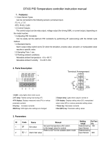
1. PREPARATION
The REX-F9000 is a temperature controller in high resolution, high accuracy and high control stability
merchandised mainly for semiconductor manufacturing equipment.
Both 1-channel and 2-channel types of controller are available. For the 2-channel type, as each
parameter is independent for each channel, one controller can be used for two loops.
1.1 Handling Procedure
Conduct necessary work according to the following procedures:
Check of product delivered
Check of model codes
Mounting
Wiring
Name of parts
Each parameter setting
Set value (SV) setting
Operation
Refer to 1.2 Check of Product Delivered on page 2.
Refer to 1.3 Check of Model Code on page 2.
Refer to 2. MOUNTING on page 3.
Refer to 3. WIRING on page 6.
Refer to 4. NAME OF PARTS on page 13.
Refer to 5. SETTING on page 16.
Refer to 5.4 SV Setting Mode on page 24.
Refer to 6. OPERATIONS on page 46.
Refer to 5.3 Mode Transfer on page 20.

1. PREPARATION
IM9000F01-E5
2
1.2 Check of Product Delivered
Check than the following items are delivered without damage.
• Mainframe: 1 unit
• Mounting bracket: 2 pieces
• Instruction manual (IM9000F01-E5): 1 copy
• Communication Instruction Manual (IM9000F02-E): 1 copy
• Power feed transformer (PFT-01 or PFT-02) [Optional]: 1 piece (Separate packing)
1.3 Check of Model Code
Check the model code from the following list to determine if the product delivered is as desired.
Model code
F9000 − − ∗ /
(1) (2) (3) (4) (5) (6) (7)
(1) Number of channel (6) Analog output [CH2] (Optional)
1: 1-channel type N: No analog output
2: 2-channel type 4: Voltage 0 to 5 V DC
6: Voltage 1 to 5 V DC
(2) Control output [CH1] 7: Current 0 to 20 mA DC
V: Voltage pulse 8: Current 4 to 20 mA DC
8: Current 4 to 20 mA DC
(7) Power feed transformer (Optional)
(3) Control output [CH2] 1: PFT-01 (100 to 120 V AC)
N: For the 1-channel type, there is 2: PFT-02 (200 to 240 V AC)
no CH2 control output. N: No power feed transformer provided
V: Voltage pulse
8: Current 4 to 20 mA DC The power feed forward function is
standard function.
(4) Power supply voltage
3: 24 V AC/DC
4: 100 to 240 V AC
(5) Analog output [CH1] (Optional)
N: No analog output
4: Voltage 0 to 5 V DC
6: Voltage 1 to 5 V DC
7: Current 0 to 20 mA DC
8: Current 4 to 20 mA DC

IM9000F01-E5 3
2. MOUNTING
2.1 Cautions for Mounting
(1) This instrument is intended to be used under the following environmental conditions. (IEC61010-1)
• OVERVOLTAGE CATEGORY II
• POLLUTION DEGREE 2
(2) Use this instrument within the following environment conditions:
• Allowable ambient temperature: 0 to 50 °C
• Allowable ambient humidity: 45 to 85 % RH (No condensation)
• Installation environment conditions: Indoor use, Altitude up to 2000 m
(3) Avoid the following conditions when selecting the mounting location:
• Rapid changes in ambient temperature which may cause condensation.
• Corrosive or inflammable gases.
• Direct vibration or shock to the mainframe.
• Water, oil, chemicals, vapor or steam splashes.
• Excessive dust, salt or iron particles.
• Excessive induction noise, static electricity, magnetic fields or noise.
• Direct air flow from an air conditioner.
• Exposure to direct sunlight.
• Excessive heat accumulation.
(4) Mount this instrument in the panel considering the following conditions:
• Provide adequate ventilation space so that heat does not build up.
• Do not mount this instrument directly above equipment that generates large amount of heat
(heaters, transformers, semi-conductor functional devices, large-wattage resistors.)
• If the ambient temperature rises above 50 °C, cool this instrument with a forced air fan, cooler,
etc. Cooled air should not blow directly on this instrument.
• In order to improve safety and the immunity to withstand noise, mount this instrument as far
away as possible from high voltage equipment, power lines, and rotating machinery.
High voltage equipment: Do not mount within the same panel.
Power lines: Separate at least 200 mm.
Rotating machinery: Separate as far as possible.
• For correct functioning mount this instrument in a horizontal position.
(5) In case this instrument is connected to a supply by means of a permanent connection a switch or
circuit-breaker shall be included in the installation. This shall be in close proximity to the
equipment and within easy reach of the operator. It shall be marked as the disconnecting device for
the equipment.
To prevent electric shock or instrument failure, always turn off the power before
mounting or removing the instrument.
WARNING
!

2. MOUNTING
IM9000F01-E5
4
2.2 Dimensions
Engineering unit: mm
91.8
96
(106)
91.8
1001296
Fig. 2.1 Dimensions
92
0
+0.8
25
19.5
(*2)
68 (*2)
70 (*2)
(*1)
92
0
+0.8
63 (*2)
(*1)
30
Mounting dimensions
2-M4
59
50
59
±0.5
±1
±0.2
(*1): Minimum (*2): Maximum
Fig. 2.2 Panel cutout Fig. 2.3 Dimensions
(Power feed transformer)

2. MOUNTING
IM9000F01-E5
5
2.3 Mounting Procedures
1. Mount the panel cutout corresponding to the number of units on the panel by referring to panel
cutout dimensions.
2. Insert the instrument into the panel from the panel cutout.
3. Insert the projections at the bottom of the bracket into the slots at the top of the controller
(Fig. 2.4 ).
4. Then tighten the mounting bracket setscrew from the rear with a Phillips screwdriver. Do not
over tighten the bracket setscrew. (Fig. 2.4 )
[Recommended tighten torque: 0.3 Nm or less (3 kgfcm or less)]
5. Set the other mounting bracket in the same way as in 3 and 4.
Slot
Bracket setscrew
Mounting
bracket
Fig. 2.4 Mounting

6 IM9000F01-E5
3. WIRING
3.1 Cautions for Wiring
(1) For RTD input connection, use lead wires with small lead wire resistance and also with the small
resistance difference between each of 3 or 4 lead wires.
(2) To avoid noise induction, keep input signal wire away from instrument power line, load lines and
power lines of other electric equipment.
(3) Signal connected to Voltage input and Current input shall be low voltage defined as “SELV”
circuit per IEC 60950-1.
(4) If there is electrical noise in the vicinity of the instrument that could affect operation, use a noise
filter.
• Shorten the distance between the twisted power supply wire pitches to achieve the most effective
noise reduction.
• Always install the noise filter on a grounded panel. Minimize the wiring distance between the
noise filter output and the instrument power supply terminals to achieve the most effective noise
reduction.
• Do not connect fuses or switches to the noise filter output wiring as this will reduce the
effectiveness of the noise filter.
Instrument powe
r
terminals
Instrument power
Twist these leadwires
IN
Minimize
distance
Shorten distance between pitches
Noise
filter
OUT
(5) Allow approximately 5 to 6 seconds for contact output when the instrument is turned on.
Use a delay relay when the output line is used for an external interlock circuit.
(6) Power supply wiring must be twisted and have a low voltage drop.
(7) This instrument has no power supply switch nor fuses. Therefore, install the fuse close to the
instrument and the switch, if required.
- Fuse type: Time-lag fuse
- Recommended fuse rating: Rated voltage: 250 V
- Rated current: 1 A
To prevent electric shock or instrument failure, do not turn on the power until all
wiring is completed. Make sure that the wiring is correct before applying power
to the instrument.
WARNING
!

3. WIRING
IM9000F01-E5
7
(8) This instrument with 24 V power supply is not provided with an overcurrent protection device.
For safety install an overcurrent protection device (such as fuse) with adequate breaking capacity
close to the instrument.
- Fuse type: Time-lag fuse (Approved fuse according IEC60127-2 and/or UL248-14)
- Fuse rating: Rated current: 0.8 A
(9) For an instrument with 24 V power supply input, supply power from “SELV” circuit defined as
IEC 60950-1.
(10) A suitable power supply should be considered in end-use equipment. The power supply must be
in compliance with a limited-energy circuits (maximum available current of 8 A).
(11) Use the solderless terminal appropriate to the screw size.
- Screw size: M3 × 8
- Recommended tightening torque: 0.4 Nm [4 kgfcm]
- Maximum allowance tighten torque: 1.0 Nm [10 kgfcm]
- Specified solderless terminals: With isolation
- Applicable wire: Solid/twisted wire of 0.25 to 1.65 mm
2
(12) Make sure that during field wiring parts of conductors can not come into contact with adjacent
conductive parts
(13) Even when only one channel is used for the 2-channel type of controller, connect sensors to both
channels. Otherwise, this controller judges that the input line breaks to be set to the FAIL state.
(14) When no contact input (DI) is used, always short the contact input (DI) terminals (Nos. 6 and 7).
Otherwise, no control can be started by the front key or via communication.

3. WIRING
IM9000F01-E5
8
3.2 Terminal Configuration
Conduct wiring by referring to following diagrams.
1
2
3
4
5
6
7
8
9
10
11
33
34
35
36
37
38
39
40
41
42
43
22
23
24
25
26
27
28
29
30
31
32
12
13
14
15
16
17
18
19
20
21
A
100 to 240 V
AC L
N
2
3
24 V
DC
+
−
2
3
24 V
AC
L
N
2
3
Power terminals
1
Ground
4
5
NO
FAIL
Output terminals
6
7
DI
+
−
7
8
9
SG
T/R(A)
T/R(B)
Contact input
Input terminals
Communication
terminals
10
11
Input by power
feed transformer
(Optional)
Power feed
input
Input terminals
Rear terminals
FAIL:
Relay contact output
250 V AC, 1 A
(Resistive load) 1 "a" contact
Contact open when error occurs
NO: Normally open
RS-485
When no contact
input (DI) is used,
always short the
contact input (DI)
terminals (Nos. 6
and 7).
Control RUN/STOP
transfer
Power supply voltage Power consumption
85 to 264 V AC (50/60 Hz ) 13 VA max. (at 100 V AC)
[Including power supply voltage variation] 19 VA max. (at 240 V AC)
(Rating: 100 to 240 V AC) 11 VA max. (at 24 V AC)
8.16 W [340 mA] max. (at 24 V DC)
21.6 to 26.4 V AC (50/60 Hz )
[Including power supply voltage variation] Contact input
(Rating: 24 V AC) Number of input point: 1 point
Input type: Dry contact input
21.6 to 26.4 V DC Resistance value judged that the contact opens:
[Including power supply voltage variation] 500 kΩ or more
(Rating: 24 V DC) Resistance value judged that the contact closed:
10 Ω or less

3. WIRING
IM9000F01-E5
9
As input, different types of input (3-wire and 4-wire systems) can be connected to CH1 and
CH2.
Control output (CH1)
Voltage pulse output: Output voltage: 0/12 V DC
Allowable load resistance: 600 Ω or more
Current output: Output current: 4 to 20 mA DC
Resolution: 13 bits or more
Allowable load resistance: 600 Ω or less
Alarm output (CH1)
Number of output points: 2 points [Relay contact output 250 V AC, 1 A (Resistive load) 1a contact]
Electrical life : 50,000 times or more (Rated load)
Input (CH1)
Input: RTD input: Pt100 Ω (JIS/IEC), JPt100 Ω
Corresponding to the 3- and 4-wire systems.
Influence of input lead: 0.04 °C or less (Per wire: 10 Ω or less)
1
2
3
4
5
6
7
8
9
10
11
33
34
35
36
37
38
39
40
41
42
43
22
23
24
25
26
27
28
29
30
31
32
12
13
14
15
16
17
18
19
20
21
A
Rear terminals
12
13
OUT
Control output terminals (CH1)
+
−
14
15
Voltage pulse
Current
Alarm output terminals (CH1)
16
ALM1
Alarm 1
ALM2
Alarm 2
NO
NO
Input terminals (CH1)
21
A
20
19
RTD
A'
A
B'
B
RTD input
NO: Normally open
4-wire system
3-wire system

3. WIRING
IM9000F01-E5
10
As input, different types of input (3-wire and 4-wire systems) can be connected to CH1 and
CH2.
Control output (CH2)
Voltage pulse output: Output voltage: 0/12 V DC
Allowable load resistance: 600 Ω or more
Current output: Output current: 4 to 20 mA DC
Resolution: 13 bits or more
Allowable load resistance: 600 Ω or less
Alarm output (CH2)
Number of output points: 2 points [Relay contact output 250 V AC, 1 A (Resistive load) 1a contact]
Electrical life: 50,000 times or more (Rated load)
Input (CH2)
Input: RTD input: Pt100 Ω (JIS/IEC), JPt100 Ω
Corresponding to the 3- and 4-wire systems.
Influence of input lead: 0.04 °C or less (Per wire: 10 Ω or less)
1
2
3
4
5
6
7
8
9
10
11
33
34
35
36
37
38
39
40
41
42
43
22
23
24
25
26
27
28
29
30
31
32
12
13
14
15
16
17
18
19
20
21
A
Rear terminals
22
23
OUT
Control output terminals (CH2) *
+
−
24
25
Voltage pulse
Current
Alarm output terminals (CH2) *
26
ALM1
Alarm 1
ALM2
Alarm 2
NO
NO
Input terminals (CH2) *
31
30
29
RTD
A'
A
B'
B
RTD input
NO: Normally open
4-wire system
3-wire system
For the 2-channel type,
always connect sensors
to CH1 and CH2.
* Use only for 2-channel type.
32

3. WIRING
IM9000F01-E5
11
Analog output (Optional)
Number of output points: 1 point (1-channel type)
2 points (2-channel type)
Output types: Voltage output: 0 to 5 V DC, 1 to 5 V DC
Current input: 0 to 20 mA DC, 4 to 20 mA DC
Allowable load resistance: Voltage output: 1 k Ω or more
Current input: 600 Ω or less
Output impedance: Voltage output: 0.1 Ω or less
Current input: 5 MΩ or more
Terminal configuration (Power feed transformer)
1
2
3
4
5
6
7
8
9
10
11
33
34
35
36
37
38
39
40
41
42
43
22
23
24
25
26
27
28
29
30
31
32
12
13
14
15
16
17
18
19
20
21
A
Rear terminals
40
41
AO
Output terminals (CH2)
*
Out
p
ut terminals
(
CH1
)
* Use only for 2-channel type.
+
−
42
43
AO
+
−
Analog output
Analog output
(Optional)
(Optional)
1
2
3
4
5
6
7
8
OUT
10 V AC
6 7
IN
100 to 120 V AC
or
200 to 240 V AC
2 3
Output terminals
Input terminals

3. WIRING
IM9000F01-E5
12
3.3 Wiring Example
1-channel type
1
2
3
4
5
6
7
8
9
10
11
33
34
35
36
37
38
39
40
41
42
43
22
23
24
25
26
27
28
29
30
31
32
12
13
14
15
16
17
18
19
20
21
A
Fast-blow
fuse
+
−
SSR
RTD input
(3-wire system)
Alarmer
FAIL output
Host computer
(Control RUN/STOP)
Dry contact
input
RS-232C/
RS-485
converter
RS-485
(2-wire system)
RS-232C
Power
supply
Power feed transformer
Power feed
input
A
nalog output (CH1)
Controlled
object
Load
Rear terminals
INOUT
Recorder
8
7
6
5
4
3
2
1
Power
supply
(Load)
When the host computer is for Windows 95/98/NT, use a RS-232C/RS-485 converter of the
automatic send/receive select type.
Recommended: CD485, CD485/V manufactured by Data Link, Inc. or equivalent.

IM9000F01-E5 13
4. NAME OF PARTS
(12)
SET
MODE
MONI CH
CH
PV
SV
AT MAN
ALM1
ALM2
FAIL
(1)
(2)
(3)
(4)
(5)
(6)
(7)
(8)
(9)
(10)
(11)
(1) Measured value (PV) display unit [Green]
• Displays measured value (PV).
• Displays various each parameter symbol set value depending on the instrument.
(2) Set value (SV) display unit [Orange]
• For the 2-channel type, measured value (PV) is displayed.
• Displays set value (SV) and various set values.
(3) Indication lamps
• AT (Autotuning lamp) [Green]: Flashes during autotuning execution.
• MAN (Manual lamp) [Green]: Lights in the manual mode.
• ALM1, ALM2 (Alarm lamps) [Red]: ALM1: Lights when alarm 1 output is turned on.
ALM2: Lights when alarm 2 output is turned on.
• FAIL (Failure lamp) [Red]: Lights in the fail status.

4. NAME OF PARTS
IM9000F01-E5
14
(4) Bar-graph display unit
• Manipulated output value (MV) display:
When manipulated output value (MV) becomes 0 % or less, the dot at the left end of the bar-graph
only flashes and when it exceeds 100 %, that at the right end flashes.
[Example of display]
0 50 100
• Deviation display:
The dots at both ends of bar-graph light to indicate deviation display.
[Example of display]
−
0+
(5) (Up key)
• Used to increase numerals.
• Mode selection is made.
(6) CH (Channel key)
The selection of CH1 and CH2 is made.
(7) (Down key)
• Used to decrease numerals.
• Mode selection is mode.
(8) (Shift key)
Used when the cursor (brightly lit) is moved to the digit whose numeric value needs to be changed
for set value change.
(9) MONI (Monitoring key)
Used to call up the CH1PV/CH2PV, PV/SV or MV display.
(10) (Set key)
• Used for parameter registration/calling up.
• Used to call up "SV setting mode," "Operator set mode" or "Setup mode."
SET
/