
For more information, visit www.desatech.com
WARNING: If the information in this manual is not
followed exactly, a re or explosion may result causing
property damage, personal injury or loss of life.
— Do not store or use gasoline or other ammable
vapors and liquids in the vicinity of this or any other
appliance.
— WHAT TO DO IF YOU SMELL GAS
• Do not try to light any appliance.
• Do not touch any electrical switch; do not use any
phone in your building.
• Immediately call your gas supplier from a neighbor’s
phone. Follow the gas supplier’s instructions.
• If you cannot reach your gas supplier, call the re
department.
— Installation and service must be performed by a quali-
ed installer, service agency or the gas supplier.
INSTALLER: Leave this manual with the appliance
CONSUMER: Retain this manual for future reference.
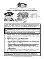
VENTED DECORATIVE GAS LOG APPLIANCE
OWNER’S OPERATION AND INSTALLATION MANUAL
MODELS
VTD-18N-TKA,
VTD-18P-TKA,
VTD-24N-TKA AND
VTD-24P-TKA
These logs are approved by the manufacturer for instal-
lation in listed indoor and outdoor solid fuel burning
replaces. See warranty for additional information.

www.desatech.com
111826-03H2
SAFETY
WARNING: Improper instal-
lation, adjustment, alteration,
service or maintenance can
cause injury or property damage.
Refer to this manual for correct
installation and operational
procedures. For assistance or
additional information consult
a qualified installer, service
agency or the gas supplier.
This appliance may be installed
in an aftermarket,* permanently
located, manufactured (mobile)
home, where not prohibited by
local codes.
This appliance is only for use
with type of gas indicated on
rating plate. This appliance is
not convertible for use with
other gases.
* Aftermarket: Completion of sale, not for
purpose of resale, from the manufacturer
WARNING: This appliance
is for installation only in a
solid-fuel burning masonry or
UL127 factory-built replace,
constructed of noncombustible
material and connected to a
working ue. (See page 6 for
minimum ue opening.)
TABLE OF CONTENTS
Safety .................................................................. 2
Local Codes......................................................... 4
Unpacking............................................................ 4
Product Identication ........................................... 5
Installation ........................................................... 5
Operation ........................................................... 10
Cleaning and Maintenance ................................ 12
Inspecting Burners............................................. 13
Troubleshooting ................................................. 14
Specications .................................................... 17
Service Hints ..................................................... 17
Technical Service............................................... 17
Wiring Diagram .................................................. 18
Replacement Parts ............................................ 19
Accessories ....................................................... 19
Parts .................................................................. 20
Warranty ..............................................Back Cover
WARNING: This is a gas-red
heater. It uses air (oxygen) from
the room in which it is installed.
Provisions for adequate combus-
tion and ventilation air must be
provided. Refer to the National
Fuel Gas Codes, ANSI Z233.1/
NFPA 54, Air for Combustion and
Ventilation.
State of Massachusetts: Installa-
tion must be made by a licensed
plumber or gas tter in the Com-
monwealth of Massachusetts.
IMPORTANT: Read this owner’s
manual carefully and completely
before trying to assemble, op-
erate or service this log set.
Improper use of this log set can
cause serious injury or death
from burns, fire, explosion,
electrical shock and carbon
monoxide poisoning.
WARNING: This product
contains and/or generates
chemicals known to the State
of California to cause cancer or
birth defects or other reproduc-
tive harm.
WARNING: Keep ue open
when operating unit.

www.desatech.com
111826-03H 3
DANGER: Carbon monoxide
poisoning may lead to death!
Carbon Monoxide Poisoning: Early signs of
carbon monoxide poisoning resemble the u,
with headaches, dizziness or nausea. If you
have these signs, log set may not be working
properly. Get fresh air at once! Have log set
serviced. Some people are more affected by
carbon monoxide than others. These include
pregnant women, people with heart or lung
disease or anemia, those under the inuence
of alcohol and those at high altitudes.
Natural and Propane/LP Gas: Natural and
propane/LP gases are odorless. An odor-
making agent is added to the gas. The odor
helps you detect a gas leak. However, the
odor added to the gas can fade. Gas may be
present even though no odor exists.
Make certain you read and understand all
warnings. Keep this manual for reference. It
is your guide to safe and proper operation of
this log set.
WARNING: Any change to
this log set or its controls can
be dangerous.
WARNING: Do not use a blow-
er insert, heat exchanger insert
or other accessory not approved
for use with this appliance.
WARNING: Do not allow fans
to blow directly into replace.
Avoid any drafts that alter burner
ame patterns.
Due to high temperatures, the
appliance should be located out
of trafc and away from furniture
and draperies.
Do not place clothing or other
ammable material on or near
the appliance. Never place any
objects on heater.
SAFETY
Continued
Log set becomes very hot when
running. Keep children and
adults away from hot surface to
avoid burns or clothing ignition.
Log set will remain hot for a time
after shutdown. Allow surface to
cool before touching.
Carefully supervise young chil-
dren when they are in the room
with log set. When using hand-
held remote accessory, keep
selector switch in OFF position
to prevent children from turning
on burners with remote.
You must operate this appliance
with a replace screen in place.
Make sure replace screen is
closed before running appliance.
Keep the appliance area clear
and free from combustible ma-
terials, gasoline and other am-
mable vapors and liquids.
1. This appliance, as supplied, is only for
use with type of gas indicated on rating
plate.
2. If you smell gas
• shut off gas supply
• do not try to light any appliance
• do not touch any electrical switch; do not
use any phone in your building
• immediately call your gas supplier from a
neighbor’s phone. Follow gas supplier’s
instructions
• if you cannot reach your gas supplier,
call the re department
3. Never install log set
• in a recreational vehicle
• where curtains, furniture, clothing or
other ammable objects are less than
42" from front, top or sides of log set
• in windy or drafty areas

www.desatech.com
111826-03H4
4. Before installing in a solid fuel burning
replace, chimney ue and rebox must
be cleaned of soot, creosote, ashes
and loose paint by a qualied chimney
cleaner. Creosote will ignite if highly
heated. Inspect chimney ue for damage.
If damaged, repair ue before operating
appliance.
5. You must operate this log set with replace
screen in place and fully closed. Any glass
doors must be open during operation.
6. This log set is designed to be smokeless.
If logs ever appear to smoke, turn off appli-
ance and call a qualied service person.
Note: During initial operation, slight
smoking could occur due to log curing
and burning of manufacturing residues.
You may wish to add more ventilation by
opening a window.
7. To reduce creation of soot, follow instructions
in Cleaning and Maintenance, page 12.
8. Installation and provisions for combus-
tion and ventilation air must conform
with the National Fuel Gas Codes, ANSI
Z233.1/NFPA 54, Air for combustion and
Ventilation.
SAFETY
Continued
9. Do not run log set
• where ammable liquids or vapors are
used or stored
• under dusty conditions
10. Do not burn solid fuel in replace after
installing log set. Do not use this log
set to cook food or burn paper or other
objects.
11. Do not use appliance if any part has been
exposed to or under water. Immediately
call a qualied service technician to in-
spect room heater and to replace any
part of control system and any gas control
which has been under water.
12. Turn log set off and let cool before servic-
ing, installing or repairing. Only a qualied
service person should install, service or
repair log set.
13. Provide adequate clearances around air
openings.
14. The receiver on this unit (see Figure 12,
page 9) has an antenna that has been
attached with adhesive. DO NOT remove
or alter placement of this antenna as this
will short circuit receiver.
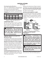
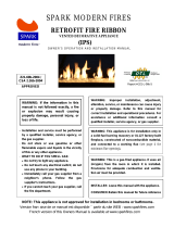
Figure 1 - Log Set in Packing Box
Carton Tray
with Handles
LOCAL CODES
Install and use log set with care. Follow all local
codes. In the absence of local codes, use the
latest edition of the National Fuel Gas Code
ANSI Z223.1/NFPA 54*
*Available from:
American National Standards Institute, Inc.
1430 Broadway
New York, NY 10018
National Fire Protection Association, Inc.
Battery March Park
Quincy, MA 02269
UNPACKING
CAUTION: Do not remove data
plates from grate assembly. Data
plates contain important warranty
and safety information.
1. Remove contents from side compart-
ments (see Figure 1).
2. Remove log set by lifting tray handles. Set
tray on oor.
3. Remove log set from tray by cutting
zip ties.
4. Check heater for any shipping damage.
If heater is damaged call DESA Heating,
LLC at 1-866-672-6040 for replacement
parts before returning to dealer.

www.desatech.com
111826-03H 5
PRODUCT IDENTIFICATION
Figure 2 - Product Identication (Ramp
Pan Burner)
Log Set
Control
Knobs
Chassis
Assembly
SPECIFICATIONS (W.C.)
FUEL INLET PRESSURE MANIFOLD
PRESSURE
Min. Max.
NG
7" 10.5" 3.5"
LP
11" 14" 10"
Figure 3 - Technical Information Chart
Remote
Receiver
Receiver
Cover Log
INSTALLATION
WARNING: The Massachu-
setts State Board requires all
installations be performed by
a Licensed Plumber or Gas Fit-
ter. Massachusetts state code
requires all vent dampers be
welded open or removed.
WARNING: A qualied ser-
vice person must install this ap-
pliance. Follow all local codes.
WARNING: Before installing
in a solid fuel burning replace,
the chimney ue and rebox
must be cleaned of soot, creo-
sote, ashes and loose paint by
a qualified chimney cleaner.
Creosote will ignite if highly
heated. A dirty chimney ue may
create and distribute soot within
the house. Inspect chimney ue
for damage. If damaged, repair
ue damper before operating
appliance.
NOTICE: Installation, service and
repair of this appliance must be
performed by a qualied installer,
service agency, company or
gas supplier experienced with
this type of gas appliance. Only
factory authorized components
listed in these instructions may
be used in accordance with
manufacturer's instructions and
all codes and requirements of
the authority having jurisdiction.
Any modications to or use of
unauthorized components or ac-
cessory items will void manufac-
turer’s warranty and may result
in a hazardous condition.
INSTALLATION AND CLEARANCES
Figure 3 shows technical information regard-
ing installation of your gas log set. Please
make sure that all specications shown are
applicable before installation is attempted.
WARNING: Failure to posi-
tion parts in accordance with
these diagrams or failure to use
only parts specically approved
with this appliance may result
in property damage or personal
injury.

www.desatech.com
111826-03H6
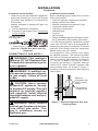
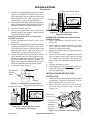
Figure 5 - Attaching Damper Clamp
Manufactured
Fireplace
Masonry
Fireplace
Damper
Damper
Clamp
Damper
Damper
Clamp
Damper
CHECK GAS TYPE
Use the correct gas type (natural or propane/
LP) for your unit. If your gas supply is not
correct, DO NOT install this gas log set. Call
dealer where you bought the appliance for
proper type of appliance.
WARNING: This appliance
is equipped for either natural
gas or propane/LP gas but not
both. Gas type is indicated on
the rating plate. Field conver-
sion is not permitted.
VENTING SPECIFICATIONS FOR
INSTALLATION
The replace chimney ue and vent must be
drafting properly. To check vent for proper draft-
ing, light a tightly rolled newspaper on one end
and place it to inside front edge of replace.
Observe smoke and be sure vent is properly
drawing it up the chimney. If smoke spills out
into room, extinguish ame and remove any
obstruction until proper venting is achieved.
The chimney ue must remain open a mini-
mum of 43 sq. inches of free air opening dur-
ing operation of this log set. A multipurpose
damper clamp is provided to x damper in
position.
For Massachusetts Residents Only: Instal-
lation of this vented gas log set in the Com-
monwealth of Massachusetts requires the
damper be permanently removed or welded
in the fully open position.
INSTALLATION
Continued
Minimum ue sizes shown in Figure 3, page 5,
are based on a 6' chimney height using round
pipe. Your minimum ue size will vary based
on input rate and chimney height. Refer to the
National Fuel Gas Code ANSI Z223.1/NFPA
54, Section 6.6 for details.
INSTALLING DAMPER CLAMP
Secure damper stop clamp to edge of damper
as shown in Figure 5. If for any reason this
clamp doesn't work on your replace, another
suitable clamp or permanent stop must be
installed, or damper blade must be cut or
removed.
Flue Opening Specications
Note: This vented appliance must be installed
only in a solid-fuel burning replace con-
structed of noncombustible material.
The replace must include a ue and vent-
ing system with minimum openings shown
in Figure 4.
LOG SIZING REQUIREMENTS
Log
Size
Minimum Firebox Size
Min. Flue
Size
Height Depth
Front
Width
Rear
Width*
18" 20" 14" 32" 22" 8"
24" 20" 14" 39" 25" 8"
* Measured at 14" depth.
Figure 4 - Sizes and Clearances
INSTALLING APPLIANCE
ASSEMbLY
WARNING: If installing in a
sunken replace, special care is
needed. You must raise replace
oor to allow access to appliance
controls. This will insure ad-
equate air ow and guard against
sooting. Raise replace oor with
noncombustible material. Make
sure material is secure.
CAUTION: Do not pick up ap-
pliance assembly by logs. This
could damage unit. Only handle
assembly by grates.
IMPORTANT: Make sure appliance is level. If
unit is not level, unit will not work properly.

www.desatech.com
111826-03H 7
INSTALLATION
Continued
CONNECTING TO GAS SUPPLY
WARNING: This appliance
requires 3/8" NPT National Pipe
Thread) inlet connection to pres-
sure regulator.
WARNING: A qualied ser-
vice person must connect heater
to gas supply. Follow all local
codes.
CAUTION: Never connect
propane/LP appliance directly
to propane/LP supply. This unit
requires an external regulator
(not supplied). Install external
regulator between unit and pro-
pane/LP supply.
WARNING: Never connect
natural gas replace to private
(non-utility) gas wells. This
gas is commonly known as
wellhead gas.
Installation Items Needed
Before installing log set, make sure you have
items listed below.
• external regulator (supplied by installer)
• piping (check local codes)
• sealant (resistant to propane/LP gas)
• equipment shutoff valve*
• test gauge connection*
• sediment trap
• tee joint
• pipe wrench
• approved exible gas line with gas connec-
tor (if allowed by local codes) (provided)
* A CSA design-certied equipment shutoff
valve with 1/8" NPT tap is an acceptable al-
ternative to test gauge connection. Purchase
optional CSA design-certified equipment
shutoff valve from your dealer.
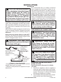
For propane/LP units, installer must supply
an external regulator. The external regulator
will reduce incoming gas pressure. You must
reduce incoming gas pressure to between
11" and 14" of water. If you do not reduce
incoming gas pressure, regulator damage
could occur. Install external regulator with
vent pointing down as shown in Figure 7.
Pointing vent down protects it from freezing
rain or sleet.
Figure 6 - Flexible Gas Hose and Gas
Regulator
Figure 7 - External Regulator with Vent
Pointing Down
Propane/LP
Supply Tank
External
Regulator with
Vent Pointing
Down
Control Valve
Flexible Gas Hose
with Regulator
Installation Items Needed
• control cover kit (provided with appliance)
• approved exible gas hose and ttings
(provided with appliance) (if allowed by
local codes)
• sealant (resistant to propane/LP gas, not
provided)
1. Position appliance in replace.
2. Connect to gas supply (see Connecting
to Gas Supply).

www.desatech.com
111826-03H8
INSTALLATION
Continued
CAUTION: Use only new, black
iron or steel pipe. Internally-tinned
copper tubing may be used in
certain areas. Check your local
codes. Use pipe of 1/2" diameter
or greater to allow proper gas vol-
ume to heater. If pipe is too small,
undue loss of volume will occur.
Installation must include an equipment shutoff
valve, union and plugged 1/8" NPT tap. Locate
NPT tap within reach for test gauge hook up.
NPT tap must be upstream from log set (see
Figure 8).
IMPORTANT: Install equipment shutoff valve
in an accessible location. Equipment shutoff
valve is for turning on or shutting off gas to
appliance.
Apply pipe joint sealant lightly to male NPT
threads. This will prevent excess sealant from
going into pipe. Excess sealant in pipe could
result in clogged heater valves.
WARNING: Use pipe joint
sealant that is resistant to liquid
petroleum (LP) gas.
We recommend that you install a sediment
trap in supply line as shown in Figure 8. Lo-
cate sediment trap where it is within reach for
cleaning. Install in piping system between fuel
supply and appliance. Locate sediment trap
where trapped matter is not likely to freeze.
A sediment trap traps moisture and contami-
nants. This keeps them from going into heater
controls. If sediment trap is not installed or is
installed wrong, heater may not run properly.
CAUTION: Avoid damage to
gas control. Hold gas control
with wrench when connecting it
to gas piping and/or ttings.
CHECKING GAS CONNECTIONS
WARNING: Test all gas piping
and connections, internal and
external to unit, for leaks after
installing or servicing. Correct
all leaks at once.
WARNING: Never use an
open ame to check for a leak.
Apply a noncorrosive leak detec-
tion uid to all joints. Bubbles
forming show a leak. Correct all
leaks at once.
CAUTION: Make sure exter-
nal regulator has been installed
between propane/LP supply
and appliance. See guidelines
under Connecting to Gas Sup-
ply, page 7.
PRESSURE TESTING GAS SUPPLY
PIPING SYSTEM
Test Pressures In Excess Of 1/2 PSIG
(3.5 kPa)
1. Disconnect appliance with its appliance
main gas valve (control valve) and equip-
ment shutoff valve from gas supply piping
system. Pressures in excess of 1/2 psig
will damage appliance regulator.
2. Cap off open end of gas pipe where equip-
ment shutoff valve was connected.
Figure 8 - Gas Connection
* Purchase the optional CSA design-certied
shutoff valve from your dealer.
** Minimum inlet pressure for purpose of input
adjustment.
Approved Flexible
Gas Hose (If
allowed by local
codes)
CSA Design-
Certied
Equipment
Shutoff Valve
with 1/8" NPT
Tap*
From Gas
Meter (5" W.C.**
to 10.5" W.C.
Pressure)
3" Min.
Pipe Cap Tee
Nipple Joint
Sediment Trap

www.desatech.com
111826-03H 9
Figure 9 - Equipment Shutoff Valve
Equipment
Shutoff
Valve
Open
Closed
Figure 11 - Checking Gas Joints
(Natural Gas Only)
Equipment Shutoff Valve
Gas Meter
INSTALLATION
Continued
3. Pressurize supply piping system by either
opening propane/LP supply tank valve
for propane/LP gas or opening main gas
valve located on or near gas meter for
natural gas, or using compressed air.
4. Check all joints of gas supply piping system.
Apply noncorrosive leak detection uid to
all joints. Bubbles forming show a leak.
5. Correct all leaks at once.
6. Reconnect appliance and equipment
shutoff valve to gas supply. Check recon-
nected ttings for leaks.
Test Pressures Equal To or Less Than
1/2 PSIG (3.5 kPa)
1. Close equipment shutoff valve (see
Figure 9).
2. Pressurize supply piping system by either
opening propane/LP supply tank valve
for propane/LP gas or opening main gas
valve located on or near gas meter for
natural gas, or using compressed air.
3. Check all joints from gas meter to equip-
ment shutoff valve for natural gas or pro-
pane/LP supply to equipment shutoff valve
for propane/LP (see Figures 10 and 11).
Apply noncorrosive leak detection uid to
all joints. Bubbles forming show a leak.
4. Correct all leaks at once.
Figure 10 - Checking Gas Joints
(Propane/LP Gas Only)
Equipment Shutoff Valve
Propane/LP Tank
PRESSURE TESTING APPLIANCE GAS
CONNECTIONS
1. Open equipment shutoff valve (see
Figure 9).
2. Open main gas valve located on or near
gas meter for natural gas or open pro-
pane/LP supply tank valve.
3. Make sure control knob of appliance is in
OFF position.
4. Check all joints from equipment shutoff
valve to gas control (see Figures 10 and
11). Apply noncorrosive leak detection
uid to all joints. Bubbles forming show a
leak.
5. Correct all leaks at once.
6. Light appliance (see Operation, page 10).
Check all other internal joints for leaks.
7. Turn off appliance.
INSTALLING RECEIVER AND
COVER LOG
1. Place receiver into position beside chassis
in replace. Receiver should lay at on
oor of replace (see Figure 12).
2. Place receiver cover log over receiver.
This will hide receiver from view (see
Figure 12).
Figure 12 - Receiver and Cover Log
Log Set
Receiver Flat
on Service
Receiver
Cover Log
Antenna
on Top of
Receiver

www.desatech.com
111826-03H10
SET
OFF
STAND
BY
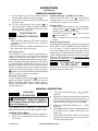
Figure 13 - Control Panel for Remote
OPERATION
5. Make sure ON/OFF switch is in "–" (ON)
position.
WARNING: burner will come
on automatically within one min-
ute after pilot burner is lighted.
6. Press buttons and at the same
time. A short acoustic signal conrms start
sequence has begun.
Further short acoustic signals (0.2 sec.,
1 Hz) indicate ignition process until it is
completed and main gas ows. If pilot is
already lit, motor will turn on (max. ame
height) while buttons are pressed down. If
pilot does not light, see Troubleshooting,
page 14.
7. Press to turn on main burner and in-
crease ame height. Press to decrease
ame height and shut off main burner.
REMOTE OPERATION
FOR YOUR SAFETY
READ bEFORE LIGHTING
WARNING: Keep ue open
when operating unit.
WARNING: If you do not fol-
low these instructions exactly,
a re or explosion may result
causing property damage, per-
sonal injury or loss of life.
A. This appliance has a pilot which must
be lighted by hand. When lighting pilot,
follow these instructions exactly.
B. BEFORE LIGHTING smell all around
the appliance area for gas. Be sure to
smell next to the oor because some
gas is heavier than air and will settle
on the oor.
WHAT TO DO IF YOU SMELL GAS
• Do not try to light any appliance.
• Do not touch any electric switch; do
not use any phone in your building.
• Immediately call your gas supplier
from a neighbor’s phone. Follow the
gas supplier’s instructions.
• If you cannot reach your gas supplier,
call the re department.
C. Use only your hand to push in or turn
the gas control knob. Never use tools.
If knob will not push in or turn by hand,
don’t try to repair it, call a qualied ser-
vice technician or gas supplier. Force
or attempted repair may result in a re
or explosion.
D. Do not use this appliance if any part
has been under water. Immediately call
a qualied service technician to inspect
the appliance and to replace any part of
the control system and any gas control
which has been under water.
REMOTE LIGHTING
INSTRUCTIONS
NOTICE: During initial operation
of new appliance, metallic com-
ponents may emit an odor as
paint and assembly compounds
are heated and cured. Be sure
to provide adequate fresh air if
odors are detected.
CAUTION: A mild gas ash
within 10 seconds is normal
during shutdown of this heater.
Remain clear of hearth area for
the entire shutdown process to
avoid possible injury.
1. STOP! Read safety information, above.
2. Make sure equipment shutoff valve is
fully open.
3. Turn motor knob clockwise to OFF
position.
4. Wait ve (5) minutes to clear out any gas.
Then smell for gas, including near the
oor. If you smell gas, STOP! Follow “B”
in safety information, above. If you don’t
smell gas, go to next step.

www.desatech.com
111826-03H 11
8. Short tapping of either button allows
incremental change in ame height.
9. Press OFF button to switch off main gas
and pilot gas.
10. To turn off burners only, press to
decrease ame height and shut off main
burner. Close equipment shutoff valve
(see Figure 9, page 9).
FUNCTIONS OF
REMOTE CONTROL
battery
• After charged battery has been correctly
installed, remote hand set is ready for
operations.
• Remove battery if remote handset will not
be used more than one year.
Changing Code
The control is radio frequency operated. A
code (chosen from among 4,000 available
codes) is preset for all valves, but can be
changed if required (15 additional codes avail-
able). Change DIP switch position. (DIP switch
is located inside hand held control at top of
battery compartment.) Press receiver's reset
button on bottom of receiver module until you
hear a second (longer) signal. When pressing
button on remote handset in the following
20 sec., receiver learns new code.
Shut Off Procedure
To save battery power; press to turn main
gas to pilot gas. Press OFF button to shut off
heater including pilot ame. Heater can be
shut off with ON/OFF switch, thus disabling
remote hand set.
OPERATION
Continued
REMOTE OPERATION
Setting Display ( °C/24h and °F/12h)
Press and hold OFF and until display
changes from °F (and 12 hour clock) to °C
(and 24 hour clock) or vice versa.
Setting Time
• After connecting battery or by simultane-
ously pressing and display will start
to ash. You are in SET mode.
• From SET mode press to set hour and
to set minute.
• Wait or press OFF to return to manual
mode.
Battery Replacement
Remote handset battery needs to be changed
when LED is dim. Battery life expectancy is
2 to 3 years. If 4 "AA" batteries are used in
receiver, replacement is recommended at the
beginning of heating season. Battery needs
to be changed when acoustic error message
appears during ignition (see Identifying Error
Signals from Receiver on page 16).
TO TURN OFF GAS
TO APPLIANCE
Press OFF button on remote control to switch
off main gas and pilot gas.
MANUAL OPERATION
LIGHTING
PROCEDURE
WARNING: Manual lighting
must be performed by a qualied
service person.
The system has a "MANUAL OVERRIDE"
feature that allows you to light with a match.
Lighting with a Match
1. STOP! Read safety information, page 10.
2. Make sure equipment shutoff valve is
fully open.
3. Turn motor knob clockwise to OFF
position.
4. Wait (5) minutes to clear any gas and then
smell for gas around heater and near oor. If
you smell gas, STOP! follow "B" on page 10.
If you do not smell gas, go to next step.
5. Make sure ON/OFF switch is in "–" (ON)
position.
6. With MAN knob on valve in MAN position,
a metallic core is visible. (see Figure 14,
page 12).
7. Push and hold down metal core fully by
using a non-sharp object such as a pen.
This lets pilot gas ow.

www.desatech.com
111826-03H12
OPERATION
Continued
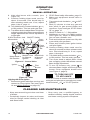
Lighting with Piezo Ignitor
1. Disconnect ignitor cable from receiver and
connect to Piezo Ignitor Tab (see Figure
14 and Wiring Diagram on page 18).
Figure 15 - Pilot
Pilot
Burner
Ignitor
Figure 14 - Control Valve
Piezo
Ignitor
Tab
Metallic Core
for Manual
Ignition
Piezo
Ignitor
ON/OFF Switch
Microswitch
MAN Knob
in Manual
Position
Motor Knob in
ON Position
8 Wire Receiver Jack
8. Light pilot burner with a match, (see
Figure 15).
9. Continue holding down metal core for
about 10 seconds. Pilot should stay lit
after releasing metal core. If not, repeat
steps 1 thru 4, page 11.
10. Turn MAN knob counterclockwise
to ON position. This lets main gas ow.
11. Turn Motor knob to adjust ame. Knob has
a slipping clutch that allows manual ame
height adjustment as well as adjustment
to pilot gas.
• Keep area around log set clean and clear
of debris.
• Periodically inspect air mixer and burner
tube for foreign matter blocking air inlet
and ame holes.
MANUAL OPERATION
2. STOP! Read safety information, page 10.
3. Make sure equipment shutoff valve is
fully open.
4. Turn motor knob clockwise to OFF
position.
5. Wait (5) minutes to clear any gas and
then smell for gas around heater and
near oor. If you smell gas, STOP! follow
"B" on page 10.
6. ON/OFF switch in "—" ON position.
7. MAN-knob on valve is in MAN position
(see Figure 14). When in MAN position
you can see a metallic core.
8. Push and hold down metal core fully with
a pen while pilot gas ows.
9. Press and release piezo ignitor button
until pilot lights.
10. Continue holding down metal core for
about 10 seconds and then release metal
core. Pilot should stay lit. If not, repeat
steps 1 through 4.
11. Turn MAN knob counterclockwise
to ON position. This lets main gas ow.
12. Turn motor knob to adjust ame. Knob
has a slipping clutch that allows manual
ame height adjustment.
13. To turn off burners only, press to
decrease ame height and shut off main
burner. Close equipment shutoff valve
(see Figure 9, page 9).
TO TURN GAS OFF
TO APPLIANCE
Press OFF button on remote control to switch off
main gas and pilot gas or manually turn motor-
knob clockwise to "O" OFF position.
CLEANING AND MAINTENANCE
• Once every year, a qualied agency or
certied chimney sweep should examine
and clean venting system of replace.

www.desatech.com
111826-03H 13
Figure 16 - Correct
Pilot Flame
Figure 17 - Incorrect
Pilot Flame
Figure 18 - Correct Burner Flame Pattern
Figure 19 - Incorrect Burner Flame
Pattern
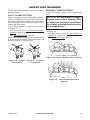
INSPECTING BURNERS
Check pilot ame pattern and burner ame
patterns often.
PILOT FLAME PATTERN
Figure 16 shows a correct pilot ame pattern.
Figure 17 shows an incorrect pilot ame pat-
tern. The incorrect pilot ame is not touching
thermocouple. When thermocouple cools,
heater will shut down.
If pilot ame pattern is incorrect, as shown
in Figure 17
• turn heater off (see To Turn Off Gas to Ap-
pliance, page 11 or 12)
• see Troubleshooting, page 14
Note: Pilot ame on natural gas units will have
a slight curve, but ame should be blue and
have no yellow or orange color.
bURNER FLAME PATTERN
Figure 18 shows correct burner ame pat-
tern.
NOTICE: Do not mistake orange
ames with yellow tipping. Dirt
or other ne particles are burned
by heater, causing brief patches
of orange ame.
If burner ame pattern is incorrect, as shown
in Figure 19,
• turn appliance off (see To Turn Off Gas to
Appliance, page 11 or 12)
• see Troubleshooting, page 14

www.desatech.com
111826-03H14
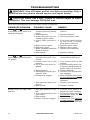
TROUBLESHOOTING
WARNING: Turn off heater and let cool before servicing. Only a
qualied service person should service and repair heater.
CAUTION: Never use a wire, needle or similar object to clean
ODS/pilot. This can damage ODS/pilot unit.
Note: All troubleshooting items are listed in order of operation.
POSSIbLE CAUSE
1. Switch in OFF position
(module gives long steady
beep)
2. Weak batteries
3. Ignitor electrode not con-
nected to ignitor cable
4. Ignitor cable pinched or
wet
5. Broken ignitor cable
6. Bad piezo ignitor
7. Ignitor electrode positioned
wrong or broken
8. Bad module
1. Gas supply turned off or
equipment shutoff valve
closed
2. Control knob not in ON
position
3. Air in gas lines when in-
stalled
4. Weak batteries
5. Depleted gas supply (pro-
pane/LP only)
6. ODS/pilot is clogged
7. Gas regulator setting is not
correct
8. Bad module
1. Inlet gas pressure is too
low
2. Wire disconnected from
gas control
3. Bad module
4. Burner orice(s) clogged
ObSERVED PRObLEM
When and are pressed
at the same time, there is no
spark at ODS/pilot
When and are pressed,
there is spark at ODS/pilot but
no ignition
Burner does not light after
pilot is lit
REMEDY
1. Push switch on valve to "–"
position
2. Replace batteries
3. Reconnect ignitor cable
4. Free ignitor cable if pinched
by any metal or tubing.
Keep ignitor cable dry
5. Replace ignitor cable
6. Replace piezo ignitor
7. Replace pilot assembly
8. Replace module
1. Turn on gas supply or open
equipment shutoff valve
2. Turn control knob to ON
position
3. Continue holding down con-
trol knob. Repeat igniting op-
eration until air is removed
4. Replace batteries
5. Contact local propane/LP
gas company
6. Clean ODS/pilot (see Clean-
ing and Maintenance, page
12) or replace ODS/pilot
assembly
7. Replace gas regulator
8. Replace module
1. Contact local natural or
propane/LP gas company
2. Reconnect leads (see Wir-
ing Diagram, page 18)
3. Replace module
4. Clean burner (see Cleaning
and Maintenance, page 12)
or replace burner orice(s)

www.desatech.com
111826-03H 15
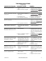
TROUBLESHOOTING
Continued
ObSERVED PRObLEM
Delayed ignition burner
Burner backfiring during
combustion
Orange ame in burner during
burner combustion
Slight smoke or odor during
initial operation (rst hour)
Appliance produces a whis-
tling noise when burner is lit
White powder residue forming
within burner box or on adja-
cent walls or furniture
Remote does not function
Appliance produces a click-
ing/ticking noise just after
burner is lit or shut off
Batteries drain quickly and
must be replaced often
REMEDY
1. Contact local natural or
propane/LP gas company
2. Clean burner (see Cleaning
and Maintenance, page 12)
or replace burner orice
1. Clean burner (see Cleaning
and Maintenance, page 12)
or replace burner orice
2. Replace damaged burner
3. Replace gas regulator
1. Check burner for dirt and
debris. If found, clean
burner (see Cleaning and
Maintenance, page 12)
2. Replace gas control
1. Problem will stop after a few
hours of operation
1. Operate burner until air is
removed from line. Have
gas line checked by local
natural or propane/LP gas
company
2. Clean burner (see Cleaning
and Maintenance, page 12)
or replace burner orice
1. Turn appliance off when
using furniture polish, wax,
carpet cleaners or similar
products
1. Replace batteries in remote
control
2. Replace module
1. This is normal with most
appliances. If noise is ex-
cessive, contact qualified
service person
1. Operate unit with screens
closed and glass doors fully
open
2. Replace receiver module
POSSIbLE CAUSE
1. Manifold pressure is too
low
2. Burner orice(s) clogged
1. Burner orice is clogged or
damaged
2. Damaged burner
3. Gas regulator defective
1. Not enough air
2. Gas regulator defective
1. Residues from manufac-
turing processes and logs
curing
1. Air in gas line
2. Dirty or partially clogged
burner orice(s)
1. When heated, vapors from
furniture polish, wax, car-
pet cleaners, etc. may turn
into white powder residue
1. Battery is not installed.
Battery power is low
2. Bad module
1. Metal expanding while
heating or contracting while
cooling
1. Operating unit with glass
doors closed
2. Bad receiver module

www.desatech.com
111826-03H16
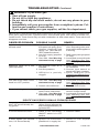
TROUBLESHOOTING Continued
WARNING: If you smell gas
• Shut off gas supply.
• Do not try to light any appliance.
• Do not touch any electrical switch; do not use any phone in your
building.
• Immediately call your gas supplier from a neighbor’s phone. Fol-
low the gas supplier’s instructions.
• If you cannot reach your gas supplier, call the re department.
IMPORTANT: Operating heater where impurities in air exist may create odors. Cleaning sup-
plies, paint, paint remover, cigarette smoke, cements and glues, new carpet or textiles, etc.,
create fumes. These fumes may mix with combustion air and create odors. These odors will
disappear over time.
POSSIbLE CAUSE
1. Appliance burning vapors
from paint, hair spray, glues,
cleaners, chemicals, new
carpet, etc. (See IMPOR-
TANT statement above)
2. Low fuel supply (propane/
LP only)
3. Gas leak. See Warning
statement at top of page
1. Not enough fresh air is
available
2. Low line pressure
3. OD S/ pi lo t is part ia ll y
clogged
1. Gas leak. See Warning
statement at top of page
2. Control valve defective
1. Foreign matter between
control valve and burner
2. Gas leak. See Warning
statement at top of page
1. B a t te ry ne ar ly dow n .
(When signal appears the
rst time approximately 10
ignitions left)
1. Cable is not connected,
ON/OFF switch is in OFF
position
1. Ignition not successful,
possible air in supply line
REMEDY
1. Open window to ventilate
room. Stop using odor caus-
ing products while appliance
is running
2. Rell supply tank (propane/
LP only)
3. Locate and correct all leaks
(see Checking Gas Con-
nections, page 8)
1. Open window and/or door
for ventilation
2. Contact local natural or
propane/LP gas company
3. C l e an ODS / pi lo t (s e e
Cleaning and Maintenance,
page 12)
1. Locate and correct all leaks
(see Checking Gas Con-
nections, page 8)
2. Replace control valve
1. Take apart gas tubing and
remove foreign matter
2. Locate and correct all leaks
(see Checking Gas Con-
nections, page 8)
1. Replace battery
1. Connect cables
1. Swi tch to ON. Rep eat
procedure
ObSERVED PRObLEM
Appliance produces un-
wanted odors
Appliance shuts off in use
(ODS operates)
Gas odor even when control
knob is in OFF position
Gas odor during combustion
Long signals (0.8 second
tone, 0.2 second break) dur-
ing ignition
5 second continuous tone
5 short signals (8.2 second
tone, 0.2 second break)
IDENTIFYING ERROR SIGNALS FROM RECEIVER

www.desatech.com
111826-03H 17
SPECIFICATIONS
VTD-18N-TKA
• Rating: 35,000/50,000 Btu/Hr
• Type Gas: Natural Gas
• Ignition: Piezo
• Manifold Pressure: 3.5" W.C.
• Inlet Gas Pressure (in. of water):
Maximum - 10.5" W.C., Minimum - 5.0" W.C.*
• Shipping Weight: 48 lbs.
* For purpose of input adjustment.
VTD-24N-TKA
• Rating: 45,000/68,000 Btu/Hr
• Type Gas: Natural Gas
• Ignition: Piezo
• Manifold Pressure: 3.5" W.C.
• Inlet Gas Pressure (in. of water):
Maximum - 10.5" W.C., Minimum - 5.0" W.C.*
• Shipping Weight: 57 lbs.
* For purpose of input adjustment.
VTD-18P-TKA
• Rating: 35,000/50,000 Btu/Hr
• Type Gas: Propane/LP
• Ignition: Piezo
• Manifold Pressure: 10" W.C.
• Inlet Gas Pressure (in. of water):
Maximum - 14" W.C., Minimum - 11" W.C.*
• Shipping Weight: 48 lbs.
* For purpose of input adjustment.
VTD-24P-TKA
• Rating: 41,000/58,000 Btu/Hr
• Type Gas: Propane/LP
• Ignition: Piezo
• Manifold Pressure: 10" W.C.
• Minimum Inlet Gas Pressure (in. of water):
Maximum - 14" W.C., Minimum - 11" W.C.*
• Shipping Weight: 57 lbs.
* For purpose of input adjustment.
SERVICE HINTS
When Gas Pressure is Too Low
• pilot will not stay lit
• burners will have delayed ignition
• heater will not produce specied heat
• propane/LP gas supply may be low
You may feel your gas pressure is too low. If
so, contact your local natural gas supplier.
TECHNICAL SERVICE
You may have further questions about installa-
tion, operation, or troubleshooting. If so, con-
tact DESA Heating, LLC at 1-866-672-6040.
When calling please have your model and
serial numbers of your heater ready.
You can also visit DESA Heating, LLC’s web
site at www.desatech.com.

www.desatech.com
111826-03H18
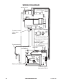
SPARK
SPARK
Pilot
4 AA Batteries
ON/OFF
Switch
Thermocurrent
Interrupter Block
SW
SW
TC
TC
Battery Compartment
MA
GR
MO
SW
PANEL
Receiver
Antenna
Ignition Cable
Thermocouple
Thermocurrent
Interrupter
Block
Combination Control
ON/OFF Switch (Optional)
OFF
ON
8 Wire
Connecting Cable
Thermocurrent Cable #2
or ON/OFF Switch
Soldered Cable
Thermocurrent
Cable #1
Motor
Knob
MAN Knob
WIRING DIAGRAM

www.desatech.com
111826-03H 19
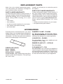
REPLACEMENT PARTS
ACCESSORIES
Note: Use only original replacement parts.
This will protect your warranty coverage for
parts replaced under warranty.
PARTS UNDER WARRANTY
Contact authorized dealers of this product. If
they can’t supply original replacement part(s),
call DESA Heating, LLC at 1-866-672-6040.
When calling DESA Heating, LLC, have
ready:
• your name
• your address
• model and serial numbers of your heater
• how heater was malfunctioning
• purchase date
Usually, we will ask you to return the part to
the factory.
PARTS NOT UNDER WARRANTY
Contact authorized dealers of this product. If
they can’t supply original replacement part(s),
call DESA Heating, LLC at 1-866-672-6040 for
referral information. A list of authorized dealers
can be found by visiting www.desatech.com.
When calling DESA Heating, LLC, have
ready:
• model and serial numbers of your heater
• the replacement part number
Purchase these accessories from your local
dealer. If they can not supply these accessories
call DESA Heating, LLC at 1-866-672-6040 for
information. You can also write to the address
listed on the back page of this manual.
FIREPLACE HOOD
Black - GA6050
Brass - GA6052
Antique Brass - GA6053
For all models. Helps deect heat away from
mantel or wall above replace. Fits openings
28" to 48" wide.
DAMPER CLAMP - GA6080
For Remote-Ready and Variable Manu-
ally-Controlled Models. Permanently opens
chimney ue damper for vented operation.
LAVA ROCK - GA6060
For all models. Order when additional rock
is desired. (1.8 lb. bag)
EMbER FLAKE KIT - 112799-01
For all models.
CLEANING KIT - CCK
For all models. Your vent-free gas appliance
requires regular cleaning and maintenance to
prevent performance problems. This kit gives
you the tools and instructions to make it easy
to clean all critical areas of your appliance.

www.desatech.com
111826-03H20
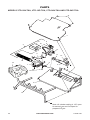
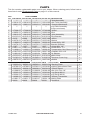
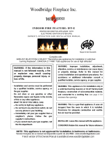
PARTS
MODELS VTD-18N-TKA, VTD-18P-TKA, VTD-24N-TKA AND VTD-24P-TKA
1
2
3
9
4
5
20
18
19
17
10
6
15
16
8
14
12
7
13
Note: Air shutter setting is 1/8" open
for natural gas and full open for
propane/LP gas.
Page is loading ...
Page is loading ...
Page is loading ...
Page is loading ...
-
 1
1
-
 2
2
-
 3
3
-
 4
4
-
 5
5
-
 6
6
-
 7
7
-
 8
8
-
 9
9
-
 10
10
-
 11
11
-
 12
12
-
 13
13
-
 14
14
-
 15
15
-
 16
16
-
 17
17
-
 18
18
-
 19
19
-
 20
20
-
 21
21
-
 22
22
-
 23
23
-
 24
24


Desa Tech VTD-24P-TKA Owner's manual
- Type
- Owner's manual
- This manual is also suitable for
Ask a question and I''ll find the answer in the document
Finding information in a document is now easier with AI
Related papers
-
Comfort Glow CVTR18 User manual
-
FMI VTD-18N-PDG User manual
-
FMI VF-24N-PDG Owner's manual
-
Desa Tech VF-18N-PJD Owner's manual
-
Desa Tech CGR30N Owner's manual
-
FMI VF-24P-EMU User manual
-
-
Barbeques Galore BVMR2 Owner's manual
-
-
Other documents
-
 Spark LBS-OD36 Owner's Operation And Installation Manual
-
 Woodbridge Fire Feature Owner's manual
-
-
Spark Modern Fires LBS-OD 24 Installation guide
-
 Design Dynamics VF-30P-PJD User manual
-
 Design Dynamics VF-24N-PDG User manual
-
Pleasant Hearth VL-WO30D Installation guide
-
 Spark Modern Fires LBS36E 3ft Installation guide
-
 Woodbridge IFF-IPS Owner's manual
-
FMI LPA6001 Operating instructions


