Page is loading ...

Owner’s Manual
Thank you for purchasing the Edirol VMC-1 Video Optimizer/Media
Converter.
Designed to deliver video and audio of a quality that rivals professional
equipment, the VMC-1 provides a rich array of image-correction
functionality and the capability to convert between analog and DV. It also
provides four knobs that let you quickly and easily make adjustments to the
image. Analog video such as VHS and eight-millimeter can be cleaned up
and saved to DVD-R or other media. You can also use the VMC-1 to export
analog video to a notebook computer that has only a DV connector.
Before using this unit, carefully read the sections entitled: “USING THE
UNIT SAFELY” and “IMPORTANT NOTES” (p. 2–3, p. 4). These sections
provide important information concerning the proper operation of the
unit. Additionally, in order to feel assured that you have gained a good
grasp of every feature provided by your new unit, Owner’s manual
should be read in its entirety. The manual should be saved and kept on
hand as a convenient reference.
Copyright © 2004 ROLAND CORPORATION
All rights reserved. No part of this publication may be reproduced in
any form without the written permission of ROLAND CORPORATION.
VMC-1(A5)_e.book 1 ページ 2005年11月14日 月曜日 午後2時51分

2
USING THE UNIT SAFELY
001
• Before using this unit, make sure to read the
instructions below, and the Owner’s
Manual.
..................................................................................................
002c
• Do not open (or modify in any way) the unit
or its AC adaptor.
..................................................................................................
003
• Do not attempt to repair the unit, or replace
parts within it (except when this manual
provides specific instructions directing you
to do so). Refer all servicing to your retailer,
the nearest Roland Service Center, or an
authorized Roland distributor, as listed on
the “Information” page.
..................................................................................................
004
• Never use or store the unit in places that
are:
• Subject to temperature extremes (e.g.,
direct sunlight in an enclosed vehicle,
near a heating duct, on top of heat-gener-
ating equipment); or are
• Damp (e.g., baths, washrooms, on wet
floors); or are
• Humid; or are
• Exposed to rain; or are
• Dusty; or are
• Subject to high levels of vibration.
..................................................................................................
007
• Make sure you always have the unit placed
so it is level and sure to remain stable.
Never place it on stands that could wobble,
or on inclined surfaces.
008c
• Be sure to use only the AC adaptor supplied
with the unit. Also, make sure the line
voltage at the installation matches the input
voltage specified on the AC adaptor’s body.
Other AC adaptors may use a different
polarity, or be designed for a different
voltage, so their use could result in damage,
malfunction, or electric shock.
..................................................................................................
008e
• Use only the attached power-supply cord.
Also, the supplied power cord must not be
used with any other device.
..................................................................................................
009
• Do not excessively twist or bend the power
cord, nor place heavy objects on it. Doing so
can damage the cord, producing severed
elements and short circuits. Damaged cords
are fire and shock hazards!
..................................................................................................
010
• This unit, either alone or in combination
with an amplifier and headphones or
speakers, may be capable of producing
sound levels that could cause permanent
hearing loss. Do not operate for a long
period of time at a high volume level, or at a
level that is uncomfortable. If you
experience any hearing loss or ringing in the
ears, you should immediately stop using the
unit, and consult an audiologist.
..................................................................................................
011
• Do not allow any objects (e.g., flammable
material, coins, pins); or liquids of any kind
(water, soft drinks, etc.) to penetrate the
unit.
Used for instructions intended to alert
the user to the risk of injury or material
damage should the unit be used
improperly.
* Material damage refers to damage or
other adverse effects caused with
respect to the home and all its
furnishings, as well to domestic
animals or pets.
Used for instructions intended to alert
the user to the risk of death or severe
injury should the unit be used
improperly.
The ● symbol alerts the user to things that must be
carried out. The specific thing that must be done is
indicated by the design contained within the circle. In
the case of the symbol at left, it means that the power-
cord plug must be unplugged from the outlet.
The symbol alerts the user to important instructions
or warnings.The specific meaning of the symbol is
determined by the design contained within the
triangle. In the case of the symbol at left, it is used for
general cautions, warnings, or alerts to danger.
The symbol alerts the user to items that must never
be carried out (are forbidden). The specific thing that
must not be done is indicated by the design contained
within the circle. In the case of the symbol at left, it
means that the unit must never be disassembled.
VMC-1(A5)_e.book 2 ページ 2005年11月14日 月曜日 午後2時51分

3
012b
• Immediately turn the power off, remove the
AC adaptor from the outlet, and request
servicing by your retailer, the nearest
Roland Service Center, or an authorized
Roland distributor, as listed on the “Infor-
mation” page when:
• The AC adaptor, the power-supply cord,
or the plug has been damaged; or
• If smoke or unusual odor occurs
• Objects have fallen into, or liquid has
been spilled onto the unit; or
• The unit has been exposed to rain (or
otherwise has become wet); or
• The unit does not appear to operate
normally or exhibits a marked change in
performance.
..................................................................................................
013
• In households with small children, an adult
should provide supervision until the child is
capable of following all the rules essential
for the safe operation of the unit.
..................................................................................................
014
• Protect the unit from strong impact.
(Do not drop it!)
..................................................................................................
015
• Do not force the unit’s power-supply cord
to share an outlet with an unreasonable
number of other devices. Be especially
careful when using extension cords—the
total power used by all devices you have
connected to the extension cord’s outlet
must never exceed the power rating (watts/
amperes) for the extension cord. Excessive
loads can cause the insulation on the cord to
heat up and eventually melt through.
..................................................................................................
016
• Before using the unit in a foreign country,
consult with your retailer, the nearest
Roland Service Center, or an authorized
Roland distributor, as listed on the “Infor-
mation” page.
101b
• The unit and the AC adaptor should be
located so their location or position does not
interfere with their proper ventilation.
..................................................................................................
102c
• Always grasp only the plug on the AC
adaptor cord when plugging into, or
unplugging from, an outlet or this unit.
..................................................................................................
103b
• At regular intervals, you should unplug the
AC adaptor and clean it by using a dry cloth
to wipe all dust and other accumulations
away from its prongs. Also, disconnect the
power plug from the power outlet
whenever the unit is to remain unused for
an extended period of time. Any accumu-
lation of dust between the power plug and
the power outlet can result in poor
insulation and lead to fire.
..................................................................................................
104
• Try to prevent cords and cables from
becoming entangled. Also, all cords and
cables should be placed so they are out of
the reach of children.
..................................................................................................
106
• Never climb on top of, nor place heavy
objects on the unit.
..................................................................................................
107c
• Never handle the AC adaptor or its plugs
with wet hands when plugging into, or
unplugging from, an outlet or this unit.
..................................................................................................
108b
• Before moving the unit, disconnect the AC
adaptor and all cords coming from external
devices.
..................................................................................................
109b
• Before cleaning the unit, turn off the power
and unplug the AC adaptor from the outlet
(p. 28).
..................................................................................................
110b
• Whenever you suspect the possibility of
lightning in your area, disconnect the AC
adaptor from the outlet.
..................................................................................................
118
• Should you remove a screw of the ground
terminal, make sure to put them in a safe
place out of children's reach, so there is no
chance of them being swallowed acciden-
tally.
VMC-1(A5)_e.book 3 ページ 2005年11月14日 月曜日 午後2時51分

4
IMPORTANT NOTES
291a
In addition to the items listed under “USING THE UNIT SAFELY” on page 2–3, please read and
observe the following:
Power Supply
301
• Do not use this unit on the same power circuit with
any device that will generate line noise (such as an
electric motor or variable lighting system).
302
• The AC adaptor will begin to generate heat after
long hours of consecutive use. This is normal, and is
not a cause for concern.
307
• Before connecting this unit to other devices, turn off
the power to all units. This will help prevent
malfunctions and/or damage to speakers or other
devices.
Placement
351
• Using the unit near power amplifiers (or other
equipment containing large power transformers)
may induce hum. To alleviate the problem, change
the orientation of this unit; or move it farther away
from the source of interference.
352a
• This device may interfere with radio and television
reception. Do not use this device in the vicinity of
such receivers.
352b
• Noise may be produced if wireless communications
devices, such as cell phones, are operated in the
vicinity of this unit. Such noise could occur when
receiving or initiating a call, or while conversing.
Should you experience such problems, you should
relocate such wireless devices so they are at a
greater distance from this unit, or switch them off.
354a
• Do not expose the unit to direct sunlight, place it
near devices that radiate heat, leave it inside an
enclosed vehicle, or otherwise subject it to temper-
ature extremes. Excessive heat can deform or
discolor the unit.
355b
• When moved from one location to another where
the temperature and/or humidity is very different,
water droplets (condensation) may form inside the
unit. Damage or malfunction may result if you
attempt to use the unit in this condition. Therefore,
before using the unit, you must allow it to stand for
several hours, until the condensation has completely
evaporated.
Maintenance
401a
• For everyday cleaning wipe the unit with a soft, dry
cloth or one that has been slightly dampened with
water. To remove stubborn dirt, use a cloth impreg-
nated with a mild, non-abrasive detergent. After-
wards, be sure to wipe the unit thoroughly with a
soft, dry cloth.
402
• Never use benzine, thinners, alcohol or solvents of
any kind, to avoid the possibility of discoloration
and/or deformation.
Additional Precautions
553
• Use a reasonable amount of care when using the
unit’s buttons, sliders, or other controls; and when
using its jacks and connectors. Rough handling can
lead to malfunctions.
556
• When connecting / disconnecting all cables, grasp
the connector itself—never pull on the cable. This
way you will avoid causing shorts, or damage to the
cable’s internal elements.
557
•A small amount of heat will radiate from the unit
during normal operation.
558b
• To avoid disturbing your neighbors, try to keep the
unit’s volume at reasonable levels (especially when
it is late at night).
559a
• When you need to transport the unit, package it in
the box (including padding) that it came in, if
possible. Otherwise, you will need to use equivalent
packaging materials.
Add
• This product is compatible with regular NTSC or
PAL video signal. In case irregular signal is input, it
may obstruct stabile operation of this product.
562
• If using some other make of connection cable, please
note the following precautions.
• Some connection cables contain resistors. Do not
use cables that incorporate resistors for
connecting to this unit. The use of such cables can
cause the sound level to be extremely low, or
impossible to hear. For information on cable
specifications, contact the manufacturer of the
cable.
Copyright
851
• Unauthorized recording, distribution, sale, lending,
public performance, broadcasting, or the like, in
whole or in part, of a work (musical composition,
video, broadcast, public performance, or the like)
whose copyright is held by a third party is
prohibited by law.
853
• Do not use this unit for purposes that could infringe
on a copyright held by a third party. We assume no
responsibility whatsoever with regard to any
infringements of third-party copyrights arising
through your use of this unit.
VMC-1(A5)_e.book 4 ページ 2005年11月14日 月曜日 午後2時51分

5
Contents
USING THE UNIT SAFELY ..................................................................... 2
IMPORTANT NOTES............................................................................... 4
Main Features ......................................................................................... 6
Names of Things and What They Do .................................................... 8
Front Panel....................................................................................................................8
Rear Panel ...................................................................................................................10
Bottom Panel (DIP Switches) ...................................................................................11
Deutsch
Bezeichnung und Funktion der Komponenten.................................. 12
Vorderseite..................................................................................................................12
Bedienungselemente auf der Rückseite..................................................................14
Unterseite (DIP-Schalter)..........................................................................................15
Français
Description............................................................................................ 16
Face avant ...................................................................................................................16
Face arrière..................................................................................................................18
Face inférieure (commutateurs DIP).......................................................................19
Italiano
Nomi delle cose e loro funzioni........................................................... 20
Pannello Pa .................................................................................................................20
Pannello posteriore....................................................................................................22
Pannello Inferiore (Interruttori DIP).......................................................................23
Español
Nombres de los diferentes elementos y sus funciones ................... 24
Panel frontal................................................................................................................24
Panel posterior ...........................................................................................................26
Panel inferior (Interruptores DIP)...........................................................................27
Setup and Connections ....................................................................... 28
Turning the Power On/Off......................................................................................28
Recording Video from a Video Tape to Your DVD Recorder............ 29
Capturing Video from a Video Tape into Your Computer................. 30
Watching Video from Your Computer on a Television ..................... 31
Appendix ............................................................................................... 32
Color Bar Output .......................................................................................................32
About Copy-protected Video...................................................................................32
Troubleshooting.........................................................................................................32
Specifications..............................................................................................................34
Index ...................................................................................................... 35
VMC-1(A5)_e.book 5 ページ 2005年11月14日 月曜日 午後2時51分

6
Main Features
Provides a resolution of 10 bits for video decoding and encoding, and 24 bits for audio AD/
DA conversion. It also has a Locked Audio function, which prevents video and audio from
drifting out of synchronization. (p. 11)
* The Locked Audio function is available only for analog input.
Differences in camera settings, type, shooting conditions, and shooting technique can
produce inconsistencies in the hue and brightness of a video image. Also, analog video that
was captured some time ago can often be lacking in vividness of color. When dubbing from
analog to analog or from analog to DV or DVD, it is very effective to use the VMC-1’s image
correction functionality (brightness, intensity, hue, contrast) to minimize such
inconsistencies in the image and improve the overall quality. You can use the knobs to make
these adjustments in real time while watching the video. (p. 9)
* Available only for analog input.
TBC is a function that cleans up the video image by eliminating the “jitter” (horizontal
shaking) caused by inaccuracies in head or tape rotation during analog videotape playback,
or due to degradation of the analog video signal. This function is very useful if you are
digitizing the video tape library you have collected over the years. You can also apply delay
to the audio to correct any timing discrepancies between the video and audio that might be
caused by the TBC. You can use a front panel button to switch this function on/off. (p. 8)
* Available only for analog input.
This function determines whether the image is moving or stationary, and if stationary,
compares the same scan lines of the preceding and following frames to separate the
brightness and color signals with high precision. This allows smearing to be reduced,
minimizing unwanted noise or blurring. You can use a front panel button to switch this
function on/off. (p. 9)
* Available only for composite input in NTSC mode.
Designed for High Quality Video and Audio, with 10-bit Video
AD/DA Conversion and 24-bit Audio AD/DA Conversion
Make Corrections in Real Time While Watching the Image
TBC (Time Base Corrector) for Stabilizing Unstable Images
Motion Adaptive 3D Y/C Separator to Reduce Color Smearing
and Graininess
VMC-1(A5)_e.book 6 ページ 2005年11月14日 月曜日 午後2時51分

7
Main Features
This function corrects inaccuracies in the timing of the video signal. Due to the mechanical
characteristics of consumer analog video decks, the preceding or following frame can
sometimes be output “out of step.” The Frame Synchronizer corrects slight inaccuracies of
the synchronization signal to prevent frame dropouts and audio dropouts. (p. 8)
* This will automatically turn on only when you use analog input.
The image from a consumer analog video camera or dubbed video tape sometimes does not
have the optimal brightness. If such an image is digitized, over-exposed whites or under-
exposed blacks may occur. AGC corrects these problems by automatically optimizing the
brightness of the analog video. You can use a front panel button to switch this function on/
off. (p. 9)
* Available only for analog input.
* Correction is not possible if the input video already has over-exposed whites or under-exposed blacks.
* You cannot convert from NTSC to PAL or vice versa.
* 16:9 screen mode is not supported.
Each set provides an S-video jack and a composite video jack, and they are capable of
providing simultaneous output. Analog input -> analog output is also supported, allowing
conversion between S-video connector <-> video jack (composite).
Frame Synchronizer Prevents Frame Dropouts and Audio
Dropouts
AGC Function Corrects Over-Exposed Whites or Under-
Exposed Blacks
Support for Both NTSC and PAL
Two Sets of Analog Output Jacks Provided
VMC-1(A5)_e.book 7 ページ 2005年11月14日 月曜日 午後2時51分

8
Names of Things and What They Do
1. DV connector 2 [DV2 IN/OUT]
Connect your DV device or computer here.
* You cannot use this simultaneously with the DV connector 1 on the VMC-1’s rear panel (p. 10). If
you attempt to use both simultaneously, your DV device may not function correctly.
2. DV input button [DV IN]
Turn this on if you want the video and audio signals from your DV device to be sent from
the analog output.
3. Analog input button [ANALOG IN]
Turn this on if you want the video and audio signals from the analog input to be sent from
the analog output.
4. Frame synchronizer indicator [FRAME SYNC]
This indicator will light when an analog video signal is input. The frame synchronizer
corrects synchronization inaccuracies caused by an unstable video signal, preventing lost
frames and audio dropouts.
5. Time base corrector button [TBC]
This corrects the image jitter that often occurs when an analog video deck is playing back.
Normally, you should leave this on. If this is on, the video and audio signals will be output
with a delay compared to the input signal, in order to allow for this processing to be
performed. If this delay is a problem, you can turn this function off.
Front Panel
VMC-1(A5)_e.book 8 ページ 2005年11月14日 月曜日 午後2時51分

Español Italiano Français Deutsch English
9
Names of Things and What They Do
6. Three-D Y/C separation button [3D Y/C]
This is available only in NTSC mode (p. 11). This will reduce certain problems that may
occur when a composite signal is being input, such as fine diagonal black and white stripes
producing a rainbow-like effect (cross color) or the appearance of small white and black dots
outlined in black (dot interference), and will clean up the signal by reducing color smearing.
Normally, you should leave this on. If there is a great deal of movement in the image, this
may cause blurring. If so, turn this off. If this is off, 2-D Y/C separation is applied.
* In PAL mode 2-D Y/C separation is always applied, so this button will be disabled.
7. Automatic brightness adjustment button [AGC]
This corrects the over-exposed whites or under-exposed blacks that can occur if the
brightness of the image is not appropriate. Normally, you should leave this on.
* Correction is not possible if the input video already has over-exposed whites or under-exposed blacks.
8. Audio level indicator
The green indicator will light when an analog audio signal is input. The red indicator will
light if the input level is excessive. Lower the audio input level until the red indicator does
not light.
9. Power button [POWER]
10. Brightness knob [BRIGHT]
Turn this knob toward the right to brighten the image, or toward the left to darken the
image.
11. Color depth knob [COLOR]
Turn this knob toward the right to deepen the color, or toward the left to lighten the color.
12. Color hue knob [HUE]
Turn this knob toward the right to give the image a more greenish hue, or toward the left to
give it a more purple hue.
13. Contrast knob [CONTRAST]
Turn this knob toward the right to make the contrast stronger, or toward the left to decrease
it.
14. Audio input level knob [AUDIO LEVEL]
Turn this knob toward the right to increase the audio input level.
* When a DV signal is input, buttons/knobs/indicators 4.–8. and 10.–14. are disabled. These functions
apply only to analog input signals.
* When a DV signal is input, the indicators of each button and the illumination around the knobs will
go out.
VMC-1(A5)_e.book 9 ページ 2005年11月14日 月曜日 午後2時51分

10
Names of Things and What They Do
1. AC adaptor jack
Connect the included AC adaptor here.
2. Ground Terminal (p. 28)
3. Analog output jacks 1/2 [ANALOG OUTPUT 1/2]
These are analog output jacks for video and audio. Connect them to your monitor television,
DVD recorder, or video deck.
4. Analog input jack [ANALOG INPUT]
This is an analog video/audio jack. Connect it to your VHS or 8mm video deck.
* If video cables are connected to both the S-video input jack and the composite input jack, the S-video
input will take priority.
5. DV connector 1 [DV1 IN/OUT]
Connect this to your DV device or computer.
* Do not use this simultaneously with the DV connector 2 located on the front panel of the VMC-1 (p.
8). If you use the two simultaneously, your DV device may not work correctly.
6. Security Slot ( )
http://www.kensington.com/
Rear Panel
6
VMC-1(A5)_e.book 10 ページ 2005年11月14日 月曜日 午後2時51分

Español Italiano Français Deutsch English
11
Names of Things and What They Do
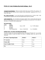
1. Video format setting switch [Video Format]
Specifies the video signal format.
2. NTSC setup level setting switch [NTSC Setup Level]
Specifies the NTSC setup level.
Select 0IRE in Japan, and select 7.5IRE in North America.
3. Locked Audio mode setting switch [Locked Audio Mode]
Specifies the Locked Audio mode for analog input.
4. Audio format setting switch [Audio Format]
Specifies the audio sampling rate and bit depth when using analog input.
5. Audio mix mode setting switch [Audio Mix Mode]
Specifies whether the sub-channels will be output when you input 32 kHz/12-bit 4-channel
audio format via DV.
6. Audio muting time setting switch
Depending on the video editing software you’re using, you may experience audio noise at the
beginning of playback if this switch is turned
ON
. In this case, use the
OFF
setting.
* When the VMC-1 is shipped from the factory, DIP switch 6 is turned
OFF
.
Make sure to turn off the power before you change the settings of the DIP switches on the
bottom panel.
Bottom Panel (DIP Switches)
OFF
NTSC
ON PAL
OFF 0IRE
ON 7.5IRE
OFF Locked
ON Unlocked
OFF 48kHz/16bit
ON 32kHz/12bit
OFF Main only
ON Mix 50% main + 50% sub
OFF Normal
ON Short
SER.NO.SER.NO.
MODELMODEL
VMC
-
1VMC
-
1
MADE IN JAPANMADE IN JAPAN
OFF ON
1Video Format NTSC PAL
OFF ON
2 NTSC Setup Level 0 IRE 7.5 IRE
3 Locked Audio Mode LOCKED UNKOCKED
4 Audio Format 48kHz /
16bit 32kHz /
12bit
5 Audio Mix Mode MAIN MAIN
+
SUB
6 Reserved
OFF ON
1
2
3
4
5
6
VMC-1(A5)_e.book 11 ページ 2005年11月14日 月曜日 午後2時51分

12
Bezeichnung und Funktion der
Komponenten
1. DV-Anschluss 2 [DV2 IN/OUT]
Schließen Sie Ihr DV-Gerät oder Ihren Computer hier an.
* Sie können diesen Anschluss nicht gleichzeitig mit dem DV-Anschluss 1 an der Rückseite des VMC-1
benutzen (p. 14). Wenn Sie versuchen, beide Anschlüsse simultan zu nutzen, kann es sein, dass Ihr
DV-Gerät nicht einwandfrei funktioniert.
2. DV Input-Taste [DV IN]
Drücken Sie diese Taste, wenn die Video- und Audiosignale Ihres DV-Geräts vom analogen
Output gesendet werden sollen.
3. Analog Input-Taste [ANALOG IN]
Drücken Sie diese Taste, wenn die Video- und Audiosignale des analogen Inputs vom
analogen Output gesendet werden sollen.
4. Bildsynchronisationsanzeige [FRAME SYNC]
Diese Anzeige leuchtet, wenn ein analoges Videosignal am Input anliegt. Die Bildsynchroni-
sation korrigiert Synchronfehler, die durch instabile Videosignale verursacht werden und
beugt Bild- und Tonverlusten vor.
5. Time-base-corrector Taste [TBC]
Korrigiert das Bildflimmern, das oft bei der Wiedergabe von analogen Videogeräten auftritt.
Normalerweise sollte der Time-base-corrector eingeschaltet sein. Die Video- und Audiosi-
gnale werden dann im Vergleich mit dem Input-Signal verzögert ausgegeben, damit die
Korrektur erfolgen kann. Wenn diese Verzögerung ein Problem darstellt, können Sie diese
Funktion ausschalten.
6. Drei-D Y/C Trenntaste [3D Y/C]
Diese Funktion ist nur in der NTSC-Betriebsart wirksam (p. 15). Hierdurch werden Probleme
reduziert, die entstehen können, wenn ein zusammengesetztes Signal ausgegeben wird,
beispielsweise feine diagonale schwarze und weiße Streifen, die einen Regenbogeneffekt
(Kreuzfarben) verursachen können, oder wenn kleine weiße und schwarze Punkte mit
Vorderseite
VMC-1(A5)_e.book 12 ページ 2005年11月14日 月曜日 午後2時51分

Español Italiano Français Deutsch English
13
Bezeichnung und Funktion der Komponenten
schwarzer Umrandung (Punktinterferenz) dargestellt werden. Das Signal wird gereinigt und
Farbverschmierungen werden reduziert. Normalerweise sollte diese Funktion eingeschaltet
sein. Wenn viele Bewegungen im Bild vorhanden sind, kann dies Unschärfe verursachen. Dann
sollte diese Funktion ausgeschaltet werden. Statt dessen wird 2-D Y/C Trennung verwendet.
* In der PAL-Betriebsart wird immer 2-D Y/C Trennung verwendet, die Taste ist daher außer Funktion.
7. Taste automatische Helligkeitsregelung [AGC]
Hierdurch werden weiße Streifen oder schwarze Gitter korrigiert, die entstehen können,
wenn die Helligkeit des Bildes nicht korrekt eingestellt ist. Normalerweise sollte diese
Funktion eingeschaltet sein.
* Eine Korrektur ist nicht möglich, wenn das Videoeingangssignal bereits weiße Streifen oder schwarze
Gitter aufweist.
8. Audiopegelanzeige
Die grüne Anzeige leuchtet, wenn ein analoges Audiosignal am Input anliegt. Die rote
Anzeige leuchtet, wenn der Eingangspegel zu hoch ist. Reduzieren Sie den Eingangspegel,
bis die rote Anzeige nicht mehr leuchtet.
9. EIN/AUS-Taste [POWER]
10. Helligkeitsregler [BRIGHT]
Durch Drehen nach rechts wird das Bild heller, durch Drehen nach links wird es dunkler.
11. Farbtiefenregler [COLOR]
Durch Drehen nach rechts werden die Farben dunkler, durch Drehen nach links werden sie
heller.
12. Farbtonregler [HUE]
Durch Drehen nach rechts erhält das Bild einen stärker grünlichen Farbton, durch Drehen
nach links einen stärker violetten Farbton.
13. Kontrastregler [CONTRAST]
Durch Drehen nach rechts wird der Kontrast verstärkt, durch Drehen nach links wird er reduziert.
14. Regler für Audio-Inputpegel [AUDIO LEVEL]
Durch Drehen nach rechts erhöhen Sie den Audio-Inputpegel.
* Wenn ein DV-Signal anliegt, sind die Tasten/Regler/Anzeigen 4. bis 8. sowie 10. bis 14. außer
Funktion. Diese Funktionen beziehen sich nur auf analoge Eingangssignale.
* Wenn ein DV-Signal am Eingang anliegt, erlöschen die Anzeigen und Beleuchtungen der Tasten und
Regler.
VMC-1(A5)_e.book 13 ページ 2005年11月14日 月曜日 午後2時51分

14
Bezeichnung und Funktion der Komponenten
1. Anschlussbuchse für Netzgerät
Hier schließen Sie das Kabel des mitgelieferten Netzgerätes an.
2. Erdungsterminal
3. Analoge Ausgangsbuchsen 1/2 [ANALOG OUTPUT 1/2]
Analoge Ausgangsbuchsen für Video und Audio. Schließen Sie diese an Ihr TV-Gerät, DVD-
Gerät oder Videorecorder an.
4. Analoge Eingangsbuchsen [ANALOG INPUT]
Dies ist eine analoge Video/Audio-Buchse. Schließen Sie diese an Ihren VHS- oder 8mm-
Videorecorder an.
* Wenn Videokabel sowohl an die S-Video-Eingangsbuchse als auch an die Kombi-Eingangsbuchse
angeschlossen sind, hat der S-Video-Eingang Priorität.
5. DV-Anschluss 1 [DV2 IN/OUT]
Schließen Sie diesen an Ihr DV-Gerät oder an Ihren Computer an.
* Verwenden Sie diesen Anschluss nicht gleichzeitig mit dem DV-Anschluss 2 an der Vorderseite des
VMC-1 (p. 12). Wenn Sie beide Anschlüsse simultan nutzen, kann es sein, dass Ihr DV-Gerät nicht
einwandfrei funktioniert.
6. Sicherheitsschlitz ( )
http://www.kensington.com/
Bedienungselemente auf der Rückseite
6
VMC-1(A5)_e.book 14 ページ 2005年11月14日 月曜日 午後2時51分

Español Italiano Français Deutsch English
15
Bezeichnung und Funktion der Komponenten
1. Schalter für Videoformateinstellung [Video Format]
Zur Einstellung des Videosignalformats.
2. Schalter für NTSC-Setup-Level [NTSC Setup Level]
Zur Einstellung des NTSC-Setup-Level.
Zur Einstellung von 0IRE in Japan und von 7.5IRE in Nordamerika.
3. Schalter für Audio-Modus-Einstellung [Locked Audio Mode]
Zur Einstellung des Locked-Audio-Modus für den analogen Input.
4. Schalter für Audioformat-Einstellung [Audio Format]
Zur Einstellung der Audiosamplingrate und der Bittiefe bei analogen Eingängen.
5. Schalter für Audiomix-Moduseinstellung [Audio Mix Mode]
Bestimmt, ob die Unterkanäle ausgegeben werden, wenn 32 kHz/12-Bit 4-Kanalaudio-
formate über DV am Input anliegen.
6. Audiostummschaltung-Einstellschalter
Je nach der verwendeten Video-Schnittsoftware können Sie Tonrauschen am Anfang der
Wiedergabe feststellen, wenn dieser Schalter auf ON gestellt ist. In diesem Fall stellen Sie ihn
auf OFF.
* Werkseitig ist beim VMC-1 der DIP-Schalter 6 auf OFF gestellt.
Bevor Sie die Einstellungen der DIP-Schalter an der Unterseite ändern, müssen Sie das
Gerät ausschalten.
Unterseite (DIP-Schalter)
OFF
NTSC
ON PAL
OFF 0IRE
ON 7.5IRE
OFF Locked
ON Unlocked
OFF 48kHz/16bit
ON 32kHz/12bit
OFF Main only
ON Mix 50% main + 50% sub
OFF Normal
ON Kurz
SER.NO.SER.NO.
MODELMODEL
VMC
-
1VMC
-
1
MADE IN JAPANMADE IN JAPAN
OFF ON
1Video Format NTSC PAL
OFF ON
2 NTSC Setup Level 0 IRE 7.5 IRE
3 Locked Audio Mode LOCKED UNKOCKED
4 Audio Format 48kHz /
16bit 32kHz /
12bit
5 Audio Mix Mode MAIN MAIN
+
SUB
6 Reserved
OFF ON
1
2
3
4
5
6
VMC-1(A5)_e.book 15 ページ 2005年11月14日 月曜日 午後2時51分

16
Description
1. Connecteur DV 2 [DV2 IN/OUT]
Connexion pour appareil DV ou ordinateur.
* Pas d’utilisation simultanée avec le connecteur DV 1 de la face arrière du VMC-1 (p. 18) En cas
d’utilisation simultanée, l’appareil DV risque de ne pas fonctionner correctement.
2. Bouton d’entrée DV [DV IN]
L’activation de cette fonction permet d’envoyer les signaux audio et vidéo de votre appareil
DV à partir de la sortie analogique.
3. Bouton d’entrée analogique [ANALOG IN]
L’activation de cette fonction permet d’envoyer les signaux audio et vidéo de l’entrée analo-
gique à partir de la sortie analogique.
4. Indicateur de synchronisation d’images [FRAME SYNC]
Cet indicateur s’allume lorsqu’un signal vidéo analogique arrive en entrée. Le synchroniseur
d’images corrige les imprécisions dues à l’instabilité du signal vidéo, et empêche la perte
d’images ou les drop-outs audio.
5. Bouton de correction du temps [TBC]
Cette fonction corrige l’instabilité de l’image, fréquente à la lecture avec un magnétoscope
analogique. En principe, cette option reste activée. Lorsqu’elle est activée, les signaux audio
et vidéo sortent en retard par rapport au signal d’entrée pour permettre leur traitement. Si ce
retard pose un problème, la fonction peut être désactivée.
Face avant
VMC-1(A5)_e.book 16 ページ 2005年11月14日 月曜日 午後2時51分

Español Italiano Français Deutsch English
17
Description
6. Bouton de séparation Y/C trois D [3D Y/C]
Disponible uniquement en mode NTSC (p. 19). Réduit une série de problèmes pouvant se
présenter lorsqu’un signal composite arrive en entrée, par exemple de fines rayures diago-
nales en noir et blanc produisant un effet d’arc-en-ciel (battement couleur) ou l’apparition de
petits points noirs et blancs entourés de noir (interférence ponctuelle), et nettoie le signal en
réduisant la bavure des couleurs. En principe, cette option reste activée. Si l’image comporte
beaucoup de mouvement, elle peut apparaître floue. Dans ce cas, désactiver la fonction ; la
séparation Y/C 2-D est alors appliquée.
* En mode PAL, la séparation Y/C 2-D est toujours appliquée ; ce bouton n’a donc aucun effet.
7. Bouton d’ajustage automatique de la luminosité [AGC]
Ce bouton corrige les stries blanches et les barres noires pouvant se produire lorsque la
luminosité de l’image n’est pas appropriée. En principe, cette option reste activée.
* La correction n’est pas possible si la vidéo d’entrée comporte déjà des stries blanches ou des barres
noires.
8. Indicateur de niveau audio
Le témoin vert s’allume lorsqu’un signal audio analogique arrive en entrée. Le témoin rouge
s’allume si le niveau d’entrée est excessif. Réduire le niveau d’entrée audio jusqu’à extinction
du témoin rouge.
9. Bouton de mise sous tension [POWER]
10. Bouton de luminosité [BRIGHT]
Tourner ce bouton vers la droite pour éclaircir l’image, ou vers la gauche pour l’assombrir.
11. Bouton de saturation des couleurs [COLOR]
Tourner ce bouton vers la droite pour des couleurs plus saturées, ou vers la gauche pour des
couleurs plus légères.
12. Bouton de teinte des couleurs [HUE]
Tourner ce bouton vers la droite pour une image plus verdâtre, ou vers la gauche pour des
teintes plus pourpre.
13. Bouton de contraste [CONTRAST]
Tourner ce bouton vers la droite pour augmenter le contraste, ou vers la gauche pour le
réduire.
14. Bouton de niveau d’entrée audio [AUDIO LEVEL]
Tourner ce bouton vers la droite pour augmenter le niveau d’entrée audio.
* Lorsqu’un signal DV parvient en entrée, les boutons/molettes/témoins 4.-8. et 10.-14. sont désactivés.
Ces fonctions ne s’appliquent qu’aux signaux d’entrée analogiques.
* En cas d’entrée d’un signal DV, les témoins de chaque bouton et l’éclairage autour des boutons
s’éteint.
VMC-1(A5)_e.book 17 ページ 2005年11月14日 月曜日 午後2時51分

18
Description
1. Adaptateur jack CA
Point de connexion de l’adaptateur CA fourni.
2. Borne de mise à la terre
3. Jacks de sortie analogique 1/2 [ANALOG OUTPUT 1/2]
Prises jack de sortie analogique pour vidéo et audio, à brancher sur l’écran de télévision, le
graveur DVD ou le magnétoscope.
4. Prise jack d’entrée analogique [ANALOG INPUT]
Prise jack vidéo/audio analogique. Se branche sur votre magnétoscope VHS ou 8 mm.
* L’entrée S-vidéo est prioritaire lorsque des câbles vidéo sont connectés sur la prise jack d’entrée S-
vidéo et la prise jack d’entrée composite.
5. Connecteur DV 1 [DV1 IN/OUT]
Se branche sur appareil DV ou ordinateur.
* Ne pas utiliser en même temps que le connecteur DV 2 situé sur la face avant du VMC-1 (p. 16). En
cas d’utilisation simultanée, l’appareil DV risque de ne pas fonctionner correctement.
6. Verrouillage ( )
http://www.kensington.com/
Face arrière
6
VMC-1(A5)_e.book 18 ページ 2005年11月14日 月曜日 午後2時51分

Español Italiano Français Deutsch English
19
Description
1. Commutateur de réglage du format vidéo [Video Format]
Définit le format du signal vidéo.
2. Commutateur de réglage NTSC [NTSC Setup Level]
Définit le niveau de paramétrage NTSC.
Sélectionner 0IRE au Japon et 7.5IRE en Amérique du Nord.
3. Commutateur de mode audio verrouillé [Locked Audio Mode]
Définit le mode Audio verrouillé pour entrée analogique.
4. Commutateur de réglage du format audio [Audio Format]
Définit la profondeur de bits et la fréquence d’échantillonnage audio pour les entrées analo-
giques.
5. Commutateur de mode Audio mix [Audio Mix Mode]
Détermine si les sous-canaux fonctionneront en sortie lorsqu’un format audio 4 canaux 32
kHz/12 bits est introduit en entrée via DV.
6. Commutateur de réglage silencieux
Selon le logiciel d'édition vidéo utilisé, un bruit audio peut se faire entendre au début de la
lecture si ce commutateur est en position MARCHE (ON). Dans un tel cas, le mettre en
position ARRÊT (OFF).
* Lorsque le VMC-1 est expédié de la fabrique, le commutateur DIP 6 est en position ARRÊT (OFF).
Mettre l’appareil hors tension avant de modifier le réglage des commutateurs DIP sur la
face inférieure.
Face inférieure (commutateurs DIP)
OFF
NTSC
ON PAL
OFF 0IRE
ON 7.5IRE
OFF Locked
ON Unlocked
OFF 48kHz/16bit
ON 32kHz/12bit
OFF Main only
ON Mix 50% main + 50% sub
OFF Normal
ON Court
SER.NO.SER.NO.
MODELMODEL
VMC
-
1VMC
-
1
MADE IN JAPANMADE IN JAPAN
OFF ON
1Video Format NTSC PAL
OFF ON
2 NTSC Setup Level 0 IRE 7.5 IRE
3 Locked Audio Mode LOCKED UNKOCKED
4 Audio Format 48kHz /
16bit 32kHz /
12bit
5 Audio Mix Mode MAIN MAIN
+
SUB
6 Reserved
OFF ON
1
2
3
4
5
6
VMC-1(A5)_e.book 19 ページ 2005年11月14日 月曜日 午後2時51分

20
Nomi delle cose e loro funzioni
1. Connettore DV 2 [DV2 IN/OUT]
Connettere il vostro apparecchio Dv o computer qui.
* Non è possibile usarlo contemporaneamente con il connettore DV 1 ed il pannello posteriore del VMC-
1. (p. 22). Se vengono usati contemporaneamente, è possibile che il vostro apparecchio DV non
funzioni correttamente.
2. Pulsante d’ingresso del DV [DV IN]
Accendere se desiderate che i segnali video e audio del vostro apparecchio DV vengano
inviati dall’uscita analogica.
3. Pulsante d’ingresso analogico [ANALOG IN]
Accendere se desiderate che i segnali video e audio dell’ingresso analogico vengano inviati
dall’uscita analogica.
4. Indicatore del sincronizzatore dell’immagine [FRAME SYNC]
Questo indicatore si accende quando viene immesso un segnale video analogico. Il
sincronizzatore dell’immagine corregge tutte le imprecisioni della sincronizzazione causate
da un segnale video instabile, evitando in questo modo la perdita d’immagine e la caduta del
suono.
5. Pulsante del correttore del tempo base [TBC]
Serve a correggere l’instabilità dell’immagine che spesso si verifica quando un apparecchio
video analogico sta riproducendo. Di norma occorre tenere accesa questa funzione. Se viene
accesa, i segnali video e audio verranno emessi con un certo ritardo rispetto al segnale
d’ingresso e ciò per consentire lo svolgimento dell’operazione. Se il ritardo rappresenta un
problema, è possibile spegnere questa funzione.
6. Pulsante di separazione 3-D Y/C [3D Y/C]
È disponibile solo con la modalità NTSC (p. 23). Riduce alcuni problemi che si possono
verificare quando viene emesso un segnale composito, come per esempio sottili linee
diagonali bianche e nere che producono un effetto arcobaleno (colore trasversale) o che
causano l’apparizione di punti bianchi e neri (interferenza di punti) e depura il segnale
Pannello Pa
VMC-1(A5)_e.book 20 ページ 2005年11月14日 月曜日 午後2時51分
/