Page is loading ...

Installation information
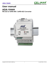
METTLER TOLEDO MultiRange
Weighing terminals IND690 / IND690xx / IND690-24V
www.mt.com/support

Congratulations on choosing the quality and precision of METTLER TOLEDO. Proper
use according to these instructions and regular calibration and maintenance by our
factory-trained service team ensure dependable and accurate operation, protecting
your investment. Contact us about a ServiceXXL agreement tailored to your needs and
budget.
We invite you to register your product at www.mt.com/productregistration so we can
contact you about enhancements, updates and important notifications concerning
your product.

Contents
Installation information 22012803F 07/09 3
IND690 / IND690xx / IND690-24V
Contents
Page
1 Safety instructions ....................................................................... 4
1.1 Safety instructions for IND690xx..................................................... 4
1.2 Safety instructions for IND690-24V................................................. 6
1.3 Safety instructions for IND690........................................................ 7
2 Introduction................................................................................. 8
2.1 Documentation............................................................................. 8
2.2 Housing variants .......................................................................... 8
2.3 Software application...................................................................... 8
2.4 Possible applications .................................................................... 9
2.5 Connections................................................................................. 10
2.6 Interfaces..................................................................................... 10
3 Commissioning ........................................................................... 14
3.1 Mounting the panel unit................................................................. 14
3.2 Mounting the desk unit .................................................................. 15
3.3 Connecting the weighing platform................................................... 27
3.4 Configuring COM1 ........................................................................ 30
3.5 Connecting the ProfibusDP-690 ..................................................... 30
3.6 Marking and sealing on verified weighing platforms.......................... 33
3.7 Particular points when commissioning the IND690xx ....................... 34
3.8 Mains connection / connecting 24 V power supply ........................... 36
4 Retrofitting .................................................................................. 38
4.1 Opening terminal .......................................................................... 38
4.2 Mounting push-on modules ........................................................... 39
4.3 Installing AnalogScale-690............................................................ 42
4.4 Installing Ethernet-690 .................................................................. 43
4.5 Installing the ProfibusDP-690 ........................................................ 45
4.6 Installing WLAN-690..................................................................... 46
4.7 Installing Bluetooth-690 ................................................................ 49
4.8 Installing AlibiMemory-690............................................................ 50
4.9 Closing terminal ........................................................................... 51
5 Technical data............................................................................. 52
5.1 Technical data of terminal.............................................................. 52
5.2 Dimensional drawings .................................................................. 56
5.3 Technical data for interfaces........................................................... 57
6 Accessories................................................................................. 66

Safety instructions
4Installation information 22012803F 07/09
IND690 / IND690xx / IND690-24V
1 Safety instructions
1.1 Safety instructions for IND690xx
The explosion-protected IND690xx weighing terminal fulfills Device category 3 and is
approved for operation in Zone 2 (gases) and Zone 22 (dusts) hazardous areas.
There is an increased risk of injury and damage when the IND690xx weighing
terminal is used in a potentially explosive atmosphere.
Special care must be taken when working in such hazardous areas. The code of
practice is oriented to the "Safe Distribution" concept drawn up by METTLER TOLEDO.
Competence ▲The IND690xx weighing terminal, accompanying weighing platforms and
accessories may only be installed, maintained and repaired by authorized
METTLER TOLEDO service personnel.
▲The mains connection may only be connected or disconnected by the owner’s
electrician.
Ex approval ▲For the exact specification please refer to the statement of conformity.
▲In order to avoid electrostatic charging the IND690xx may only be installed in
rooms or areas at which strong electric field strengths cannot occur from
experience.
▲No modifications may be made to the terminal and no repair work may be
performed on the modules. Any weighing platform or system modules that are
used must comply with the specifications contained in the installation instructions.
Non-compliant equipment jeopardizes the safety of the system, cancels the Ex
approval and renders any warranty or product liability claims null and void.
▲The cable glands must be tightened so that a strain relief of ≥ 20 N per mm cable
diameter is ensured.
▲When connecting external devices, always observe the maximum permissible
connected loads, see Page 12. It must be ensured that no voltages are fed into
the IND690xx than it itself provides. The interface parameters have to fulfill the
standard.
▲Peripheral devices without an Ex approval may only be operating in non-
hazardous areas. It must be ensured that no voltages are fed into the IND690xx
than it itself provides. In addition the maximum permissible connected loads
have to be observed, see Page 12. The interface parameters have to fulfill the
standard.
▲Also comply with the following:
– the instructions for the system modules
– the regulations and standards in the respective country
– the statutory requirement for electrical equipment installed in hazardous areas
in the respective country, e.g. EN 60079-14 and EN 61241-14
– all instructions related to safety issued by the owner

Safety instructions
Installation information 22012803F 07/09 5
IND690 / IND690xx / IND690-24V
▲The safety of a weighing system including the IND690xxx weighing terminal is
only guaranteed when the weighing system is operated, installed and maintained
in accordance with the respective instructions.
▲Before initial start-up and following service work, check the explosion-protected
weighing system for the proper condition of all safety-related parts.
Installation and
retrofitting
▲Only install or perform maintenance work on the weighing terminal, accompa-
nying weighing platforms and accessories in the hazardous zone if the following
conditions are fulfilled:
– the owner has issued a permit ("spark permit" or "fire permit"),
– the area has been rendered safe and the owner's safety co-ordinator has
confirmed that there is no danger,
– the necessary tools and any required protective clothing are provided (danger
of the build-up of static electricity).
▲In order to avoid electrostatic charging the IND690xx may only be installed in
rooms or areas at which strong electric field strengths cannot occur from
experience.
▲The certification papers (certificates, manufacturer’s declarations) must be
present.
▲Connection values of externally connectable devices and cables of other manu-
facturers must be known, e.g. capacitances, inductances and current consump-
tion.
▲Lay cables in such a way that they are protected from damage.
▲Only route cables into the housing of the system modules via the earthing cable
gland or METTLER TOLEDO plug and ensure proper seating of the seals. Ensure
that the cable shields are connected correctly and that they have a secure
connection to the housing.
▲If the weighing terminal is used in conjunction with an automatic or manual
filling plant, all of the system modules must be equipped with a permanently
wired emergency stop circuit, independent of the system circuit, in order to
prevent personal injury or damage to other items of equipment.
▲The IND690xx panel unit does not comply with any freedom-from-leaks rating.
Therefore the installer is responsible for compliance with the freedom from leaks
rating, e.g. at control cabinet installation. For Ex devices at least IP54 is required,
in case of conductive dust IP6X.
▲Establish an equipotential bonding.
▲If restricted breathing weighing cells are used, test restricted breathing.
▲If the weighing platforms are installed in a pit, test whether primary explosion
protection is required.
▲Do not connect or disconnect plugs until the IND690xx has been de-energized
for at least 5 minutes.
▲Cover unused connection sockets with protective caps.
▲Mount the labelling for operation in hazardous areas, see Section 3.7.4.
▲After connectors have been mounted, screw on the securing clamps for external
connectors.

Safety instructions
6Installation information 22012803F 07/09
IND690 / IND690xx / IND690-24V
Operation ▲Prevent the build-up of static electricity. Therefore:
– only operate the IND690xx in rooms or areas at which strong electric field
strengths cannot occur from experience,
– always wear suitable working clothes when operating or performing service
work on the system,
– do not rub or wipe off the keyboard surface with a dry cloth or glove.
▲Do not use protective hoods.
▲Prevent damage to the weighing terminal. Hairline cracks in the keyboard
membrane are also considered damage.
▲If the IND690xx weighing terminal, accompanying weighing platforms or
accessories are damaged:
– Switch off weighing terminal.
– Separate the weighing terminal from the mains in accordance with the
applicable regulations.
– Secure the weighing terminal against accidental start-up.
1.2 Safety instructions for IND690-24V
▲Never operate the IND690-24V weighing terminal in hazardous areas; there are
special scales in our product line for this purpose.
▲The IND690-24V weighing terminal may only be connected to a power supply
(storage battery or mains) having a 24 VDC SELV power circuit in accordance
with EN 60950.
▲Short-circuit danger!
Ensure that the power supply is connected properly:
brown lead +24 V
blue lead 0 V or negative pole
▲The safety of the unit is endangered if it is not operated in accordance with these
operating instructions.
▲Only authorized personnel may open the IND690-24V weighing terminal.
Competence ▲The IND690-24V weighing terminal, accompanying weighing platforms and
accessories may only be installed, maintained and repaired by authorized
METTLER TOLEDO service personnel.

Safety instructions
Installation information 22012803F 07/09 7
IND690 / IND690xx / IND690-24V
1.3 Safety instructions for IND690
▲Do not operate the IND690 weighing terminal in hazardous areas. We have
special suitable scales in our range of products for hazardous areas.
▲Ensure that the power socket outlet for the IND690 weighing terminal is earthed
and easily accessible, so that it can be de-energized rapidly in emergencies.
▲Ensure that the supply voltage at the installation site lies within in the range of
100 V to 240 V.
▲The safety of the device cannot be ensured if it is not operated in accordance with
these operating instructions.
▲Only authorized personnel may open the IND690 weighing terminal.
Competence ▲The IND690 weighing terminal, accompanying weighing platforms and
accessories may only be installed, maintained and repaired by authorized
METTLER TOLEDO service personnel.
Leakages ▲The IND690 panel unit does not comply with any freedom-from-leaks rating.
Therefore the installer is responsible for compliance with the freedom from leaks
rating, e.g. at control cabinet installation. The respective national standards
furthermore have to be observed.
IND690 in the
food area
▲In order to avoid condensation leave the device switched on when it is operated
in humid areas or is subjected to high temperature fluctuations.

Introduction
8Installation information 22012803F 07/09
IND690 / IND690xx / IND690-24V
2 Introduction
2.1 Documentation
The weighing terminal comes supplied with a CD containing all the documentation
on the IND690 weighing system.
These installation instructions describe the installation of the panel unit, the
connection of interfaces in the inside of the device as well as the mounting of
additional interfaces.
Basic information on working with the weighing terminal and on the interface settings
can be found in the operating instructions IND690-Base.
2.2 Housing variants
IND690 The IND690 weighing terminal is available as a desk unit and as a panel unit for
installation in a control cabinet.
IND690-24V The IND690-24V weighing terminal with a 24 VDC power supply is available as a
desk unit and as a panel unit for installation in a control cabinet.
IND690xx The IND690xx weighing terminal fulfills Device category 3 and is approved for
operation in Zone 2 (gases) and Zone 22 (dusts) hazardous areas. The IND690xx is
also available as a desk unit or as a panel unit.
For the exact specification of the Ex approval please refer to the statement of
conformity.
2.3 Software application
The following application software that is loaded on-board at the factory is available
for the weighing terminal:
Batch-690, Com-690, Control-690, Count-690, Fill-690, Form-690, FormXP-690,
Sum-690.

Introduction
Installation information 22012803F 07/09 9
IND690 / IND690xx / IND690-24V
2.4 Possible applications
The weighing terminals can be used for the following applications:
• Multi-scale operation with up to 4 weighing platforms at IND690 and up to
3 weighing platforms at IND690xx and IND690-24V, including weighing
platforms with an analog signal output.
• Up to 9 data interfaces
– for printing
– for exchanging data with a computer
– for connecting a barcode reader
– for controlling e.g. valves or flaps
– for connecting reference scales
– for connecting an external keyboard
Hazardous area Safe area
Zone 2 / Zone 22
Approved peripheral devices,
e. g. barcode reading pen
Zone 2 / Zone 22
Approved
weighing platforms
IND690
IND690-24V
IND690xx

Introduction
10 Installation information 22012803F 07/09
IND690 / IND690xx / IND690-24V
2.5 Connections
1Mains connection
2COM1 – standard RS232 interface
3Equipotential bonding terminal (only IND690xx)
4Optional interface connections COM2 ... COM9
2.6 Interfaces
2.6.1 Overview
By default the IND690(xx) has an RS232 interface (COM1). A maximum total of
8 further interfaces can be installed (COM2 ... COM9).
The following further interfaces are available:
1 2 43
Designation Note Design
Scales interfaces
IDNet-690 For connecting IDNet weighing platforms Push-on
modules
SICS-Scale-690 For connecting SICS weighing platforms
AnalogScale-690 For connecting analog weighing platforms Interface card
Serial interfaces
CL20mA-690 –
Push-on
modules
RS232-690 –
RS485/422-690 Can be configured as RS485 or RS422
USB-690 –
Network and field bus
connections
Ethernet-690 –
Network cardsProfibusDP-690 –
WLAN-690 –
Further interfaces
Bluetooth-690 –
Push-on
modules
4I/O-690 Digital inputs/outputs
AnalogOut-690 Digital-analog output
PS2-690 For connecting an external keyboard
AlibiMemory-690 Alibi memory Internal card

Introduction
Installation information 22012803F 07/09 11
IND690 / IND690xx / IND690-24V
2.6.2 Combination possibilities
The interfaces can be combined as follows:
Limitations The following limitations have to be observed:
• At the IND690 a maximum of 4 interface cards1) and 2 networks cards2) can be
mounted.
At the IND690xx and IND690-24V a maximum of 3 weighing interfaces3),
1 AlibiMemory and 2 network cards2) can be mounted. If Bluetooth is mounted,
only 1 network card2) can be mounted.
• WLAN-690 and AlibiMemory-690 may not be installed at the same time at the
IND690xx.
• Scale interfaces3) have to be installed without gaps beginning with COM2.
• It must be ensured that no voltages are fed into the terminal than it itself provides.
The interface parameters have to fulfill the standard.
1) AnalogScale-690 and AlibiMemory-690
2) Ethernet-690, WLAN-690, ProfibusDP-690
3) IDNet-690, SICS-Scale-690, Analog Scale-690
COM1 COM2 COM3 COM4 COM5 COM6 COM7 COM8 COM9 IND690 IND690xx IND690-24V
RS232-690 xxxxxxxxxmax. 9 max. 9 max. 9
IDNet-690 –xxxx––––max. 4 max. 3 max. 3
SICS-Scale-690 –xxxx––––max. 4 max. 3 max. 3
AnalogScale-690 –xxxx––––max. 4 max. 3 max. 3
CL20mA-690 –xxxxxxxxmax. 8 max. 8 max. 8
RS485/422-690 –xxxxxxxxmax. 8 max. 8 max. 8
USB-690 –xxxxxxxxmax. 1 max. 1 max. 1
Ethernet-690 –xxxxxxxxmax. 1 max. 1 max. 1
ProfibusDP-690 –xxxxxxxxmax. 1 max. 1 max. 1
WLAN-690 –xxxxxxxxmax. 1 max. 1 max. 1
Bluetooth-690 –xxxxxxxxmax. 4 max. 2 max. 2
4I/O-690 ––––xx–––max. 2 max. 2 max. 2
AnalogOut-690 ––––xx–––max. 2 max. 2 max. 2
PS2-690 ––––––––xmax. 1 max. 1 max. 1
AlibiMemory-690 –xxxxxxxxmax. 1 max. 1 max. 1

Introduction
12 Installation information 22012803F 07/09
IND690 / IND690xx / IND690-24V
• The following total load of the output voltages is to be observed when several
peripheral devices are connected:
IND690 IND690xx / IND690-24V
Output voltage 5 V max. 600 mA max. 100 mA to max. 300 mA,
depending on the design level *
Output voltage 12 V max. 200 mA max. 200 mA
Output voltage 24 V max. 100 mA max. 100 mA
* At the IND690xx and IND690-24V the maximum total load of the 5 V output
voltage depends on the combination of the installed interface modules and
network cards. If a combination of the interface modules or the network cards
Ethernet-690, WLAN-690, Profibus-DP-690 and Bluetooth-690 is used, the 5 V
output voltage may have a maximum load of 100 mA.
EXPLOSION HAZARD
➜When connecting several external devices to the power-limited 5 V output voltage
of the IND690xx, observe the following total connection values for the total of all
devices including cables:
Total capacity parallel on 5 V Co = max. 200 μF
Total inductance in series on 5 V Lo = max. 60 μH

Introduction
Installation information 22012803F 07/09 13
IND690 / IND690xx / IND690-24V
2.6.3 Installation scheme
Desk unit
Panel unit

Commissioning
14 Installation information 22012803F 07/09
IND690 / IND690xx / IND690-24V
3 Commissioning
3.1 Mounting the panel unit
1. Affix the supplied drilling template to the control cabinet and saw out the cut-out
for the cover exactly using the sabre saw.
2. Insert the housing (1) from the front into the cut-out.
3. Place on the securing clamps (3) on the rear and fasten them with 6 hexagon
nuts (4) and 6 washers (2). Place the washers so that the cover can be
removed easily.
1
3
3
4
2

Commissioning
Installation information 22012803F 07/09 15
IND690 / IND690xx / IND690-24V
3.2 Mounting the desk unit
3.2.1 Mounting with brackets and stands
METTLER TOLEDO offers the following options for mounting brackets and stands:
Description
IND690 wall bracket
For mounting the IND690 weighing
terminal on the wall, complete with
mounting screws, stainless
22 011 980
IND690 floor stand
For fixed mounting the IND690
weighing terminal to the floor,
complete with mounting material,
height 1000 mm, stainless
22 011 981
IND690 bench stand
For mounting the weighing terminal to
the weighing bench for KB, MB, KCC,
MCC and PBA430 weighing platforms,
height 500 mm, stainless
22 011 986
IND690 stand articulated adapter
Retrofit set for old stands, with the
exception of scale stand 00 504 439,
stainless
22 011 984
Stand base
For movable installation of the floor
stand, stainless
22 011 982
GA46 adapter
For mounting the GA46 printer in
combination with the IND690 to the
floor stand or to the wall bracket,
stainless
May not be mounted to IND690xx!
22 011 985
21
8
8
9
1
5
6
7
2
3
11
1

Commissioning
16 Installation information 22012803F 07/09
IND690 / IND690xx / IND690-24V
3.2.2 Dimensional drawings
Wall bracket
GA46 adapter
100
125
30
18
180
32
60
120
244
45 183
142
Ø9
90°±
+45°
-15°
26
Ø9
45°
350
(65)
(100)
(54) 40
80
26
Ø9

Commissioning
Installation information 22012803F 07/09 17
IND690 / IND690xx / IND690-24V
Floor stand
~ 1036
160
180°
45°
60
135
160
74
(180)
32
18
~ 60
16
30
135
40
(6)
Ø9
Ø8

Commissioning
18 Installation information 22012803F 07/09
IND690 / IND690xx / IND690-24V
Stand base
20
15
420
119.5 135
478
420
135
478
Ø9 (4x)
+10

Commissioning
Installation information 22012803F 07/09 19
IND690 / IND690xx / IND690-24V
3.2.3 Safety instructions
▲The supplied mounting material and the instructions are determined for fastening
to concrete or stone masonry and stone or concrete floors. Ensure that the
dowels are located in fixed masonry or fixed flooring.
▲Before drilling any holes ensure that there are no electrical line or pipes in the
wall or in the floor.
▲IND690 and GA46 can only be disconnected from the power supply by pulling
the power plug. The socket-outlet has to be freely accessible.
▲The GA46 adapter may not be mounted at the IND690xx, since the GA46 printer
and GA46 adapter are not approved for use in a hazardous area.
▲IND690xx does not have a power plug. The power connection has to be
connected to a suitable connection socket that is freely accessible. The terminal
can only be disconnected from the power supply by means of a suitable external
disconnecting device.
▲The distance from the weighing terminal and GA46 to the socket outlet or to the
connection socket may not exceed 2.20 m in case of wall mounting. In case of
floor mounting the distance from the cable outlet at the floor stand to the socket
outlet or connection socket may not exceed 1.20 m.
▲The power cord must be laid directly and freely to the socket outlet. It may not be
laid through holes and openings. It may not be laid in cable ducts or fastened to
the wall or other objects using cable clamps or other fastening material.
▲In addition observe the respective national standards and safety regulations.
▲During assembly and disassembly various parts of the wall bracket and at the
floor stand can be moved. Be careful not to pinch fingers or cables.
▲All the screws have to be tightened.
▲If the stand articulated adapter is screwed tight so that the terminal can be rotated
and tilted, it is possible that cables, fingers or other parts can be jammed or
pinched.
▲Ensure during assembly and disassembly in particular that the floor stand does
not tilt and that the terminal or other parts do not fall down. Risk of injury.
▲Mount the floor stand, also in connection with the stand base vertically.
Otherwise there is a danger of tilting. The stand base may not wobble. If
necessary, adjust it using the leveling feet.

Commissioning
20 Installation information 22012803F 07/09
IND690 / IND690xx / IND690-24V
3.2.4 Mounting the desk unit to the wall
Required tools
• Hand drill
• Stone drill bit ∅ 8 mm
• Open end wrench size 10 mm (1)
• Box wrench size 5.5 mm (2)
• 2 x open end wrench size 13 mm (3)
Mounting
Approximate required space
1. Drill holes in the wall in accordance with the drawing (not to scale):
4 holes, ∅ 8 mm, 60 mm deep.
2. Screw the completely premounted wall bracket (4) with the supplied dowels (7),
washers (6) and wooden screws (5) to the wall using the open end wrench (1).
3. Turn over the weighing terminal, place it on its front side on a soft surface and
loosen the 2 screws (8) on the cover rear using the box wrench (2).
4. Hang the weighing terminal into the stand articulated adapter (9) and position it
so that the holes of the stand articulated adapter and weighing terminal match.
500
100
250
75
120
Dimensions in mm
4
8
8
9
10
1
6
1
3
2
57
/