Continental Hydraulics PVR15 Manifold User manual
- Type
- User manual
Continental Hydraulics PVR15 Manifold is a versatile and powerful hydraulic pump designed for a wide range of applications. With its ability to handle pressures up to 230 psi (15.9 bar) and flow rates of up to 21 gpm (7.6 lpm), it's suitable for various industrial and mobile hydraulic systems. The pump features adjustable pressure and volume controls, enabling precise flow and pressure regulation. Its compact design and easy installation make it a practical choice for space-constrained applications.
Continental Hydraulics PVR15 Manifold is a versatile and powerful hydraulic pump designed for a wide range of applications. With its ability to handle pressures up to 230 psi (15.9 bar) and flow rates of up to 21 gpm (7.6 lpm), it's suitable for various industrial and mobile hydraulic systems. The pump features adjustable pressure and volume controls, enabling precise flow and pressure regulation. Its compact design and easy installation make it a practical choice for space-constrained applications.


-
 1
1
-
 2
2
-
 3
3
-
 4
4
-
 5
5
-
 6
6
-
 7
7
-
 8
8


Continental Hydraulics PVR15 Manifold User manual
- Type
- User manual
Continental Hydraulics PVR15 Manifold is a versatile and powerful hydraulic pump designed for a wide range of applications. With its ability to handle pressures up to 230 psi (15.9 bar) and flow rates of up to 21 gpm (7.6 lpm), it's suitable for various industrial and mobile hydraulic systems. The pump features adjustable pressure and volume controls, enabling precise flow and pressure regulation. Its compact design and easy installation make it a practical choice for space-constrained applications.
Ask a question and I''ll find the answer in the document
Finding information in a document is now easier with AI
Related papers


Other documents
-
 Crown Automotive 5012329AAK2 Installation guide
-
MYERS D65-16 and D65-20 Owner's manual
-
Flowserve PolyChem GRP Pump User Instructions
-
ITT GOULDS PUMPS 3185 Installation, Operation and Maintenance Manual
-
-
Perkins Phaser Series Workshop Manual
-
Graco Inc. 308870 User manual
-
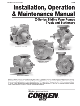 Corken Z4200 Installation, Operation & Maintenance Manual
-
Hypro 9302, 9303, 9304, 9305 & 9306 Hydraulically Driven Centrifugal Pumps Owner's manual
-
Giant P420-0021 User manual

