Page is loading ...

Quick Start Guide
Agilent Technologies
ESG Family Signal Generators
Part No. E4400-90326
Printed in USA
October 2000
Supersedes April 2000
© Copyright 1999, 2000 Agilent Technologies
Serial Number Prefixes:
(Affix Label Here)
qsg.book Page i Friday, September 22, 2000 3:13 PM

Quick Start Guide iii
Contents
1. Getting Started
The Signal Generator at a Glance . . . . . . . . . . . . . . . . . . . . . . . . . . . . . . . . . . . . 1-2
Creating an FM Signal. . . . . . . . . . . . . . . . . . . . . . . . . . . . . . . . . . . . . . . . . . . . . 1-3
Setting the Carrier Frequency. . . . . . . . . . . . . . . . . . . . . . . . . . . . . . . . . . . . 1-3
Setting the Power Level. . . . . . . . . . . . . . . . . . . . . . . . . . . . . . . . . . . . . . . . . 1-3
Setting the FM Deviation . . . . . . . . . . . . . . . . . . . . . . . . . . . . . . . . . . . . . . . 1-4
Setting the FM Rate. . . . . . . . . . . . . . . . . . . . . . . . . . . . . . . . . . . . . . . . . . . . 1-4
Turning On Frequency Modulation. . . . . . . . . . . . . . . . . . . . . . . . . . . . . . . . 1-4
Creating a Step Sweep and a List Sweep . . . . . . . . . . . . . . . . . . . . . . . . . . . . . . 1-5
Configuring a Step Sweep . . . . . . . . . . . . . . . . . . . . . . . . . . . . . . . . . . . . . . . 1-5
Turning On Continuous Step Sweep. . . . . . . . . . . . . . . . . . . . . . . . . . . . . . . 1-6
Configuring a List Sweep Using Step Sweep Data . . . . . . . . . . . . . . . . . . . 1-7
Turning On List Sweep for a Single Sweep . . . . . . . . . . . . . . . . . . . . . . . . . 1-8
Saving and Recalling an Instrument State. . . . . . . . . . . . . . . . . . . . . . . . . . . . . 1-9
Creating an Instrument State. . . . . . . . . . . . . . . . . . . . . . . . . . . . . . . . . . . . 1-9
Saving an Instrument State . . . . . . . . . . . . . . . . . . . . . . . . . . . . . . . . . . . . . 1-10
Recalling an Instrument State . . . . . . . . . . . . . . . . . . . . . . . . . . . . . . . . . . . 1-10
Setting Up a Digital Modulation in the GSM Format . . . . . . . . . . . . . . . . . . . . 1-11
Setting the Carrier Frequency. . . . . . . . . . . . . . . . . . . . . . . . . . . . . . . . . . . . 1-11
Setting the Power Level. . . . . . . . . . . . . . . . . . . . . . . . . . . . . . . . . . . . . . . . . 1-11
Selecting the Data Format. . . . . . . . . . . . . . . . . . . . . . . . . . . . . . . . . . . . . . . 1-12
Setting Up Timeslot 0 . . . . . . . . . . . . . . . . . . . . . . . . . . . . . . . . . . . . . . . . . . 1-12
Setting Up Timeslot 7 . . . . . . . . . . . . . . . . . . . . . . . . . . . . . . . . . . . . . . . . . . 1-13
Turning On the GSM Format and the Modulation . . . . . . . . . . . . . . . . . . . 1-14
2. Exploring the User Interface
Front Panel . . . . . . . . . . . . . . . . . . . . . . . . . . . . . . . . . . . . . . . . . . . . . . . . . . . . . . 2-2
Display. . . . . . . . . . . . . . . . . . . . . . . . . . . . . . . . . . . . . . . . . . . . . . . . . . . . . . . . . . 2-7
Rear Panel. . . . . . . . . . . . . . . . . . . . . . . . . . . . . . . . . . . . . . . . . . . . . . . . . . . . . . . 2-11
qsg.book Page iii Friday, September 22, 2000 3:13 PM

Quick Start Guide 1-1
ESG Family Signal Generators
1 Getting Started
This chapter will help you learn how to do the following with your signal generator:
• create an FM signal
• generate step and list sweeps
• use the save and recall functions
• set up a digital modulation in GSM format (Option UN8 only)
qsg.book Page 1 Friday, September 22, 2000 3:13 PM

1-2 QuickStartGuide
Getting Started ESG Family Signal Generators
The Signal Generator at a Glance
The Signal Generator at a Glance
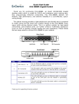
Refer to the figure and descriptions below as you use the procedures in this chapter. For
detailed front and rear panel information, refer to Chapter 2, “Exploring the User Interface.”
1. Active Entry Area. The current active function is
shown in this area.
2. Annunciators. These display annunciators show
the status of various signal generator functions.
3. Frequency Area. The current CW frequency is
shown in this portion of the display.
4. Amplitude Area. The current output power level is
shown in this portion of the display.
5 Softkey Labels. The softkey labels define the
functionsofthecorrespondingsoftkeysimmediately
to the right of the labels.
6. Softkeys. Pressing a softkey activates the function
indicated by the label on the display directly to the
left of the softkey.
7. Knob. The knob is used to increase or decrease a
numeric value.
8. Menu Keys. These hardkeys provideaccess to the
signal generator’s primary functionality.
9. RF Output Connector. This female Type-N
connector is the output connector for RF signals.
10. Numeric Keypad. The numeric keypad consists of
digit, decimal point, and backspace keys. The
backspacekeycan alsobe usedto changethe sign
of a numeric value.
11. Arrow Keys.Theup anddownarrowkeysincrease
or decrease numeric values. The left and right
arrow keys move the cursor.
12. Standby LED. This yellow LED lights when the
instrument is in standby mode.
13. Line Power LED. This green LED lights when
power is cycled on.
14. Power Switch. Pressing this hardkey toggles the
power between on and standby.
qsg.book Page 2 Friday, September 22, 2000 3:13 PM

Quick Start Guide 1-3
ESG Family Signal Generators Getting Started
Creating an FM Signal
Creating an FM Signal
This procedure will show you how to configure the signal generator to output a
frequency-modulated signal with the following characteristics:
• carrier frequency set to 104.9 MHz
• power level set to 0 dBm
• FM deviation set to 75 kHz
• FM rate set to 10 kHz
Setting the Carrier Frequency
Setting the Power Level
1. Press Preset. This sets the signal generator to its factory-defined instrument
state.
2. Press Frequency. Frequency becomes the active function and the preset value for
frequency is displayed in the active entry area.
3. Enter 104.9 using the numeric
keypad and press the MHz
softkey.
The new carrier frequency (104.900 000 00 MHz) is
shown in both the FREQUENCY area and the active entry area
of the display.
1. Press Amplitude. Amplitude becomes the active function and the preset value for
amplitude is displayed in the active entry area.
2. Enter 0 using the numeric
keypad and press the dBm
softkey.
The new power level (0.00 dBm) is shown in both the
AMPLITUDE area and the active entry area of the display.
qsg.book Page 3 Friday, September 22, 2000 3:13 PM

1-4 QuickStartGuide
Getting Started ESG Family Signal Generators
Creating an FM Signal
Setting the FM Deviation
Setting the FM Rate
Turning On Frequency Modulation
The signal generator is now configured to output a 0 dBm, frequency-modulated carrier at
104.9 MHz with the FM deviation set to 75 kHz and the FM rate set to 10 kHz. The shape of
the waveform is a sinewave.
NOTE Sine is the default selection for the FM Waveform softkey. Press More (1 of 2) to see
the softkey.
Follow these remaining steps to output the frequency-modulated signal:
1. Press FM/φM. The first level menu of FM softkeys is displayed.
2. Press the FM Dev softkey. FM deviation becomes the active function and the preset value
for FM deviation is displayed in the active entry area.
3. Enter 75 using the numeric
keypad and press the kHz
softkey.
The new FM deviation is displayed below the FM Dev softkey.
You should see 75.0000 kHz in the second line of the
softkey label.
1. Press the FM Rate softkey. FM ratebecomes the activefunction and the presetvalue for FM
rate is displayed in the active entry area.
2. Enter 10 using the numeric
keypad and press the kHz
softkey.
The new FM rate is displayed below the FM Rate softkey. You
should see 10.0000 kHz in the second line of the softkey
label.
1. Press the FM Off On softkey. FM toggles from Off to On. Notice, also, that the FM display
annunciator is turned on, indicating that you have enabled
frequency modulation.
2. Press RF On/Off. Notice that the display annunciator changes from RF OFF to
RF ON. The modulated signal is now available at the
RF OUTPUT connector.
qsg.book Page 4 Friday, September 22, 2000 3:13 PM

Quick Start Guide 1-5
ESG Family Signal Generators Getting Started
Creating a Step Sweep and a List Sweep
Creating a Step Sweep and a List Sweep
This section will show you two ways to set up the signal generator to sweep a defined set of
points. You will create a ten-point step sweep with the settings listed below, then use these
points as the basis for a new list sweep.
• frequency range from 525 MHz to 600 MHz
• power level from −20 dBm to 0 dBm
• dwell time 500 ms at each point
Configuring a Step Sweep
1. Press Preset. This sets the signal generator to its factory-defined instrument
state.
2. Press Sweep/List. The first level of sweep softkeys is displayed.
3. Press the Sweep Type List Step
softkey.
This toggles the Sweep Type List Step softkey from List to
Step.
4. Press the Configure Step Sweep
softkey.
Another menu is displayed with softkeys that you will use to
create the sweep points.
5. Press the Freq Start softkey.
Enter 525 using the numeric
keypad and press the MHz
softkey.
This sets the new start frequency for the step sweep to525 MHz.
6. Press the Freq Stop softkey.
Enter 600 using the numeric
keypad and press the MHz
softkey.
This sets the new stop frequency for the step sweep to 600 MHz.
7. Press the Ampl Start softkey.
Enter −20 using the numeric
keypad and press the dBm
softkey.
This sets the power level for the start of the step sweep to
−20 dBm.
qsg.book Page 5 Friday, September 22, 2000 3:13 PM

1-6 QuickStartGuide
Getting Started ESG Family Signal Generators
Creating a Step Sweep and a List Sweep
Turning On Continuous Step Sweep
8. Press the Ampl Stop softkey.
Enter 0 using the numeric
keypad and press the dBm
softkey.
This sets the new power level for the end of the step sweep to
0 dBm.
9. Press the # Points softkey.
Enter 10 by rotating the front
panel knob until the number
10 is displayed.
This sets the number of points in the step sweep.
10. Press the Step Dwell softkey.
Enter 500 using the numeric
keypad and pressing the msec
softkey.
This sets the dwell time for each point in the step sweep.
1. Press Return. This moves the softkey menu up one level.
2. Press the Sweep softkey. Another menu is displayed, showing you choices for sweeping
either thefrequency, amplitude, orfrequency and amplitude data.
3. Press the Freq & Ampl softkey. Selecting thissoftkey returns you tothe previousmenu andturns
the sweep function on.
4. Press the
Sweep Repeat Single Cont
softkey.
This toggles the Sweep Repeat Single Cont softkey from
Single to Cont (Continuous). Notice that the SWEEP display
annunciator is turned on, indicating that the signal generator is
sweeping.
5. Press RF On/Off. Notice that the display annunciator changes from RF OFF to
RF ON. The swept RF signal is now available at the
RF OUTPUT connector.
qsg.book Page 6 Friday, September 22, 2000 3:13 PM

Quick Start Guide 1-7
ESG Family Signal Generators Getting Started
Creating a Step Sweep and a List Sweep
Configuring a List Sweep Using Step Sweep Data
1. Press the Sweep Type List Step
softkey.
This toggles the Sweep Type List Step softkey from Step to
List.
2. Press the Configure List Sweep
softkey.
Another menu is displayed with softkeys that you will use to
create the sweep points. Notice that the display shows the
current list data. (When no list has been previously created, the
default is one point set to the signal generator’s maximum
frequency, −135 dBm, with a dwell time of 2 ms.)
3. Press the following softkeys:
More (1 of 2) >
Load List From Step Sweep >
Confirm Load From Step Sweep.
The points you defined in the step sweep are automatically
loaded into the list.
4. Press the More (2 of 2) softkey. This softkey menu along with the numeric keypad, arrow keys,
and front panel knob can be used to edit the sweep points in the
list. For more information about editing sweep points, refer to
Chapter 2, “Using Functions,” of the ESG Family Signal
Generators User’s Guide.
qsg.book Page 7 Friday, September 22, 2000 3:13 PM

1-8 QuickStartGuide
Getting Started ESG Family Signal Generators
Creating a Step Sweep and a List Sweep
Turning On List Sweep for a Single Sweep
1. Press Return. This moves the softkey menu up one level. Notice that the
Sweep softkeyisstill settosweepboth frequencyand amplitude
data.
2. Press the
Sweep Repeat Single Cont
softkey.
This toggles the Sweep Repeat Single Cont softkey from
Cont to Single. Notice that the SWEEP display annunciator is
turned off.
3. Press the Single Sweep softkey. The signal generator sweeps the points in your list once. Notice
that the SWEEP display annunciator is turned on during the
sweep.
4. Press the More (1 of 2) and
Sweep Trigger softkeys.
A menu isdisplayed showing you choicesfor triggering a sweep.
Notice that you had used the default setting, Immediate, when
you triggered the single sweep in the previous step.
5. Press the Trigger Key softkey. This sets Sweep Trigger to Trigger Key and returns you to
the previous softkey menu.
6. Press the More (2 of 2) and
Single Sweep softkeys.
This arms the sweep so that it is ready for triggering. Notice that
the ARMED display annunciator is now turned on.
7. Press Trigger. The signal generator sweeps the points in your list once and the
SWEEP display annunciator appears during the sweep.
qsg.book Page 8 Friday, September 22, 2000 3:13 PM

Quick Start Guide 1-9
ESG Family Signal Generators Getting Started
Saving and Recalling an Instrument State
Saving and Recalling an Instrument State
Using this procedure, you will learn how to save instrument settings to a memory register and
to recall the settings.
Creating an Instrument State
1. Press Preset. This sets the signal generator to its factory-defined instrument
state.
2. Press Frequency. Frequency becomes the active function and the preset value for
frequency is displayed in the active entry area.
3. Enter 800 using the numeric
keypad and press the MHz
softkey.
The new carrier frequency (800.000 000 00 MHz) is
shown in both the FREQUENCY area and the active entry area
of the display.
4. Press Amplitude. Amplitude becomes the active function, and the preset value for
amplitude is displayed in the active entry area.
5. Enter 0 using the numeric
keypad and press the dBm
softkey.
The new power level (0.00 dBm) is shown in both the
AMPLITUDE area and the active entry area of the display.
6. Press AM followed by the
AM Off On softkey.
AM toggles from Off to On. Notice also that the AM display
annunciator is turned on, indicating that you have enabled
amplitude modulation. You have now created an example
instrument state that you will save and recall.
qsg.book Page 9 Friday, September 22, 2000 3:13 PM

1-10 QuickStart Guide
Getting Started ESG Family Signal Generators
Saving and Recalling an Instrument State
Saving an Instrument State
Recalling an Instrument State
1. Press Save followed by the
Select Seq softkey.
The sequence number becomes the active function. The signal
generator displays the last sequence that you have used.
2. Enter 1 using the numeric
keypad and press the Enter
softkey.
This setsthe sequencenumberto 1. (Youcan alsouse thearrow
keys to enter the sequence number.)
3. Press the Select Reg softkey. The register number in sequence1 becomes the active function.
The signal generator either displays the last register used
[accompanied by the text: (in use)] or, if no registers are in
use, displays register 00 [accompanied by the text:
(available)].
4. Enter 1 using the numeric
keypad and press the
Select Reg softkey.
This selects register 01. (You can also use the arrow keys to
select the register number.)
5. Press the SAVE Seq[1] Reg[01]
softkey.
The current instrument settings, including the frequency,
amplitude,and modulationchanges you made, havebeen stored
in the signal generator memory.
1. Press Preset. This sets the signal generator to its factory-defined instrument
state.
2. Press Recall. Notice that the Select Seq softkey shows sequence 1. (This is
the last sequencethat you used.) Youdo not need to changethe
sequence.
3. Press the RECALL Reg softkey. The register to be recalled in sequence 1 becomes the active
function.
4. Enter 1 using the numeric
keypad and press the Enter
softkey.
Notice that your stored instrument settings have been
immediately recalled. (You can also use the arrow keys to select
the register number.)
qsg.book Page 10 Friday, September 22, 2000 3:13 PM

Quick Start Guide 1-11
ESG Family Signal Generators Getting Started
Setting Up a Digital Modulation in the GSM Format
Setting Up a Digital Modulation in the GSM Format
NOTE You must have an ESG-D or ESG-DP Series Signal Generator with Option UN8
to perform this procedure.
Using this procedure you will set up the signal generator to output a GMSK digitally
modulated signal in the GSM format with the following characteristics:
• carrier frequency set to 891 MHz
• power level set to −5 dBm
• timeslot 0 activated and configured as a Custom channel
• a fixed 4-bit repeating sequence selected as the data pattern for timeslot 0
• timeslot 7 activated and configured as a Normal channel
• 4 ones and 4 zeros selected as the data pattern for timeslot 7
Setting the Carrier Frequency
Setting the Power Level
1. Press Preset. This sets the signal generator to its factory-defined instrument
state.
2. Press Frequency. Frequency becomes the active function and the preset value for
frequency is displayed in the active entry area.
3. Enter 891 using the numeric
keypad and press the MHz
softkey.
The new carrier frequency (891.000 000 00 MHz) is
shown in both the FREQUENCY area and the active entry area
of the display.
1. Press Amplitude. Amplitude becomes the active function and the preset value for
amplitude is displayed in the active entry area.
2. Enter −5 using the numeric
keypad and press the dBm
softkey.
The new power level (-5.00 dBm) is shown in both the
AMPLITUDE area and the active entry area of the display.
qsg.book Page 11 Friday, September 22, 2000 3:13 PM

1-12 QuickStart Guide
Getting Started ESG Family Signal Generators
Setting Up a Digital Modulation in the GSM Format
Selecting the Data Format
Setting Up Timeslot 0
1. Press Mode. Then press the
following softkeys:
Real Time I/Q Baseband (if it
appears) > TDMA > GSM.
This selects the GSM communications standard.
2. Press the
Data Format Pattern Framed
softkey.
This toggles the Data Format Pattern Framed softkey from
Pattern to Framed. When you select Framed for bursting the
frameenvelope,youwill betransmittingframed data.This means
that youwill be burstingthe timeslotsthat youhave activated and
there will be no RF carrier during the off timeslots. Notice that
Configure Timeslots has become an active softkey.
1. Observe the GSM Timeslot
Pattern on the display.
Notice that the preset condition for timeslot #0 has the timeslot
turned on and configured as a Normal channel.
2. Press the Configure Timeslots
softkey and observe the softkey
menu.
The Timeslot # softkey shows that timeslot #0 is selected as
the active timeslot. The Timeslot Off On softkey shows that
timeslot #0 is turned on. Finally, the Timeslot Type softkey
shows that timeslot #0 is configured as a Normal channel.
3. Press the Timeslot Type softkey. Another menu of softkeys is displayed.
4. Press the Custom softkey. This changes the timeslot type to Custom timeslot and
automatically returns you to the previous softkey menu. Notice
that the Timeslot Type softkey has changed from Normal to
Custom. Also notice that the display shows timeslot #0
configured as a Custom timeslot.
5. Press the Configure Custom
softkey.
Another menu is displayed showing you data choices for the
timeslot’s transmission. Notice that the display has changed,
showing you a visual representation of the timeslot. Directly
below the visual representation of the timeslot, you should see
Data: PN9. PN9 is the default timeslot transmission data.
qsg.book Page 12 Friday, September 22, 2000 3:13 PM

Quick Start Guide 1-13
ESG Family Signal Generators Getting Started
Setting Up a Digital Modulation in the GSM Format
Setting Up Timeslot 7
6. Press the FIX4 softkey. This changes the transmitted data to a fixed 4-bit repeating
sequence. The default 4-bit repeating sequence of 0000 is
shown in the active entry area of the display.
7. Enter 1010 using the numeric
keypad and press the Enter
softkey.
This changes the pattern from 0000 to 1010. Directly below the
visual representation of the timeslot, you should see
Data: 1010.
1. Press Return. This moves the softkey menu up one level.
2. Press the Timeslot # softkey.
Then enter 7 usingthe numeric
keypad and press the Enter
softkey.
This selects timeslot #7 as the active timeslot. (You can also use
thearrowkeysto selectthetimeslots.)The currentactivetimeslot
(#7) is displayed in the active entry area.
3. Press the Timeslot Off On
softkey.
This toggles the Timeslot Off On softkey from Off to On.
Notice that the display now shows that timeslot #7 is turned on.
4. Press the Timeslot Type softkey. Another menu of softkeys is displayed.
5. Press the Normal softkey. This changes the timeslot type to a Normal timeslot and
automatically returns you to the previous softkey menu. Notice
that the Timeslot Type softkey has changed from Custom to
Normal. Also notice that the display shows timeslot #7
configured as a Normal timeslot.
6. Press the Configure Normal
softkey.
Another menu of softkeys is displayed, allowing you to change
the E, S, and TS fields for the Normal timeslot.
7. Press the following softkeys:
E > Other Patterns > 4 1’s & 4 0’s.
Thisfills theE fieldwith arepeating sequenceof four 1’s followed
by four 0’s. Directly below the visual representation of the
timeslot, you should see E: P4.
qsg.book Page 13 Friday, September 22, 2000 3:13 PM

1-14 QuickStart Guide
Getting Started ESG Family Signal Generators
Setting Up a Digital Modulation in the GSM Format
Turning On the GSM Format and the Modulation
The signal generator is now configured to burst two uplink timeslots with a −5.0 dBm, GMSK
digitally modulated carrier at 891 MHz. Follow these remaining steps to output the framed
data.
1. Press Return twice. This moves the softkey menu up two levels. The first GSM
softkey menu shouldbe displayed. (Thefirst softkeyin this menu
is GSM Off On.)
2. Press the GSM Off On softkey. This toggles the GSM Off On softkey from Off to On. At this
time theinternal baseband generator generatesthe internal data
patterns that you have configured for timeslots 0 and 7.
A messageis displayedwhile this processis taking place. Notice
also that the following display annunciators are turned on:
• GSM indicates that you have enabled the GSM standard.
• I/Q indicates that I/Q modulation is being generated.
• ENVLP indicates that burst is activated for transmitting
framed data.
3. Press RF On/Off. Notice that the display annunciator changes from RF OFF to
RF ON. The modulated signal is now available at the
RF OUTPUT connector.
qsg.book Page 14 Friday, September 22, 2000 3:13 PM

Quick Start Guide 2-1
ESG Family Signal Generators
2 Exploring the User Interface
This chapter provides you with an overview of your signal generator’s user interfaces:
• front panel hardkeys and connectors
• display fields and annotations
• rear panel connectors
qsg.book Page 1 Friday, September 22, 2000 3:13 PM

2-2 QuickStartGuide
Exploring the User Interface ESG Family Signal Generators
Front Panel
Front Panel
The following pages describe the numbered items shown in the figure below.
qsg.book Page 2 Friday, September 22, 2000 3:13 PM

Quick Start Guide 2-3
ESG Family Signal Generators Exploring the User Interface
Front Panel
1. EXT 1 INPUT This female BNC input connector accepts a 1-V
pk
signal for FM,
ΦM, and AM.
2. EXT 2 INPUT This female BNC input connector accepts a 1-V
pk
signal for FM,
ΦM, AM, and pulse modulation.
3. Help Press this hardkey for a short textual description of the function of
the front panel hardkeys and softkeys. Press this key again and you
will be returned to normal instrument operation.
4. Trigger Press this hardkey to begin an event (such as a step or list sweep).
This key must first be selected as the method for activating an event
by pressing the Trigger Key softkey, located in the softkey menus
associated with the event.
5. LF OUTPUT This female BNC connector is the output connector for modulation
signals generated by the LF (low frequency) source function
generator.
6. Mod On/Off This hardkey toggles all modulation signals on and off.
7. RF OUTPUT This female Type-N connector is the output connector for RF
signals.
8. RF On/Off This hardkey toggles the RF signal on and off at the RF OUTPUT
connector.
9. Numeric
Keypad
The numeric keypad consists of the digit keys (0 through 9), a
decimal point key, and a backspace key. The backspace key has dual
functions for both backspacing and changing the sign of a value
between positive and negative. Use these keys whenever the active
function requires a value input.
10. Arrow Keys The up and down arrow keys increase or decrease a numeric value.
You can also use these keys to scroll through displayed lists to select
items. The left and right arrow keys choose the highlighted digit in
the active entry area of the display; that digit can be modified by the
up and down arrow keys or the knob. You can also use these keys in
a list to select items in a row.
qsg.book Page 3 Friday, September 22, 2000 3:13 PM

2-4 QuickStartGuide
Exploring the User Interface ESG Family Signal Generators
Front Panel
11. Return The Return key cancels the current active function and moves you
from your current softkey menu to the softkey menu that precedes
it.
12. Display
Contrast
Decrease
Press this key and hold it down to cause the display background to
darken in comparison to the text on the display.
13. Display
Contrast
Increase
Press this key and hold it down to cause the display background to
brighten in comparison to the text on the display.
14. Local Press this key to return the signal generator to local (front panel)
control from remote operation.
15. Preset Press this key to set the signal generator to a known state (either
the factory-defined state or a user-defined state).
16. Standby LED This yellow LED lights when the instrument is in standby
condition. In standby, the power switch is off but the instrument is
still connected to the main power circuit by way of the power cord.
17. Line Power
LED
This green LED lights when power is cycled on to the signal
generator.
18. Power Switch Press this hardkey to turn power to the signal generator either on
(green LED on) or to standby (yellow LED on).
19. Q INPUT This connector accepts an externally supplied, analog,
quadrature-phase component of I/Q modulation. This female BNC
connector is provided only on ESG-D and ESG-DP Series Signal
Generators.
20. I INPUT This connector accepts an externally supplied, analog, in-phase
component of I/Q modulation. This female BNC connector is
provided only on ESG-D and ESG-DP Series Signal Generators.
qsg.book Page 4 Friday, September 22, 2000 3:13 PM
/