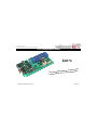
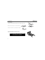
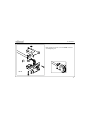
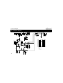
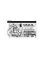
Velleman K8076 is a PIC microcontroller programmer board designed for easy programming of various PIC microcontrollers. It features an onboard configurable 40-pin ZIF socket, allowing you to work with a wide range of PICs. The device includes user-friendly PICprog2006TM software for programming and comes with a complete set of SUBD connectors for convenient connectivity. Supported controllers include PIC10F200, PIC12C508A, PIC12F629, PIC16F54, PIC16F84A, and many more.
Velleman K8076 is a PIC microcontroller programmer board designed for easy programming of various PIC microcontrollers. It features an onboard configurable 40-pin ZIF socket, allowing you to work with a wide range of PICs. The device includes user-friendly PICprog2006TM software for programming and comes with a complete set of SUBD connectors for convenient connectivity. Supported controllers include PIC10F200, PIC12C508A, PIC12F629, PIC16F54, PIC16F84A, and many more.


-
 1
1
-
 2
2
-
 3
3
-
 4
4
-
 5
5
-
 6
6
-
 7
7
-
 8
8
-
 9
9
-
 10
10
-
 11
11
-
 12
12
-
 13
13
-
 14
14
-
 15
15
-
 16
16


Velleman K8076 is a PIC microcontroller programmer board designed for easy programming of various PIC microcontrollers. It features an onboard configurable 40-pin ZIF socket, allowing you to work with a wide range of PICs. The device includes user-friendly PICprog2006TM software for programming and comes with a complete set of SUBD connectors for convenient connectivity. Supported controllers include PIC10F200, PIC12C508A, PIC12F629, PIC16F54, PIC16F84A, and many more.
Ask a question and I''ll find the answer in the document
Finding information in a document is now easier with AI
Related papers
-
Velleman WSHA8086 Operating instructions
-
Velleman K1803 User manual
-
Velleman K8044 User manual
-
Velleman K8006 Illustrated Assembly Manual
-
-
Velleman WSL8072 Owner's manual
-
-
Velleman K8042 User manual
-
-