
1760649
www.schneider-electric.com
2354235 11/2008
Altivar 61
Variable speed drives for
synchronous and asynchronous motors
Programming Manual
Software V6.6
02/2014


1760649 02/2014 3
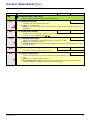
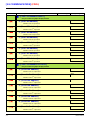
Contents
Before you begin______________________________________________________________________________________________ 4
Documentation structure________________________________________________________________________________________ 5
Software enhancements________________________________________________________________________________________ 6
Steps for setting up the drive ____________________________________________________________________________________ 9
Factory configuration _________________________________________________________________________________________ 10
Setup – Preliminary recommendations____________________________________________________________________________ 11
Graphic display terminal _______________________________________________________________________________________ 14
Description of the terminal _______________________________________________________________________________ 14
Description of the graphic screen __________________________________________________________________________ 15
First power-up – [5. LANGUAGE] menu_____________________________________________________________________ 18
Subsequent power ups__________________________________________________________________________________ 19
Programming: Example of accessing a parameter_____________________________________________________________ 20
Quick navigation _______________________________________________________________________________________ 21
Integrated display terminal _____________________________________________________________________________________ 24
Functions of the display and the keys_______________________________________________________________________ 24
Accessing menus ______________________________________________________________________________________ 25
Accessing menu parameters _____________________________________________________________________________ 26
[2. ACCESS LEVEL] (LAC-) ____________________________________________________________________________________ 27
Structure of parameter tables ___________________________________________________________________________________ 30
Interdependence of parameter values ____________________________________________________________________________ 31
Finding a parameter in this document ____________________________________________________________________________ 32
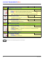
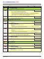
[1.1 SIMPLY START] (SIM-)____________________________________________________________________________________ 33
[1.2 MONITORING] (SUP-) ____________________________________________________________________________________ 39
[1.3 SETTINGS] (SEt-) ________________________________________________________________________________________ 48
[1.4 MOTOR CONTROL] (drC-) _________________________________________________________________________________ 64
[1.5 INPUTS / OUTPUTS CFG] (I-O-) ____________________________________________________________________________ 81
[1.6 COMMAND] (CtL-)_______________________________________________________________________________________ 110
[1.7 APPLICATION FUNCT.] (FUn-) ____________________________________________________________________________ 123
[1.8 FAULT MANAGEMENT] (FLt-) _____________________________________________________________________________ 189
[1.9 COMMUNICATION] (COM-) _______________________________________________________________________________ 215
[1.10 DIAGNOSTICS]________________________________________________________________________________________ 219
[1.11 IDENTIFICATION] ______________________________________________________________________________________ 221
[1.12 FACTORY SETTINGS] (FCS-) ____________________________________________________________________________ 222
[1.13 USER MENU] (USr-) ____________________________________________________________________________________ 225
[1.14 PROGRAMMABLE CARD] (PLC-) _________________________________________________________________________ 226
[3. OPEN / SAVE AS] ________________________________________________________________________________________ 227
[4. PASSWORD] (COd-)______________________________________________________________________________________ 229
[6 MONITORING CONFIG.] ___________________________________________________________________________________ 231
[7 DISPLAY CONFIG.] _______________________________________________________________________________________ 235
[MULTIPOINT SCREEN] _____________________________________________________________________________________ 240
Maintenance _______________________________________________________________________________________________ 241
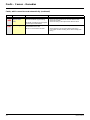
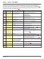
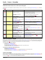
Faults – Causes – Remedies __________________________________________________________________________________ 242
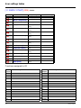
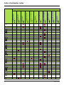
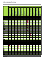
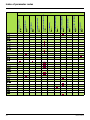
User settings tables _________________________________________________________________________________________ 248
Index of functions ___________________________________________________________________________________________ 250
Index of parameter codes_____________________________________________________________________________________ 251

4 1760649 02/2014
Before you begin
Read and understand these instructions before performing any procedure with this drive.
DANGER
HAZARD OF ELECTRIC SHOCK, EXPLOSION, OR ARC FLASH
• Only appropriately trained persons who are familiar with and understand the contents of this manual and all other
pertinent product documentation and who have received safety training to recognize and avoid hazards involved are
authorized to work on and with this drive system. Installation, adjustment, repair and maintenance must be performed
by qualified personnel.
• The system integrator is responsible for compliance with all local and national electrical code requirements as well as
all other applicable regulations with respect to grounding of all equipment.
• Many components of the product, including the printed circuit boards, operate with mains voltage. Do not touch. Use
only electrically insulated tools.
• Do not touch unshielded components or terminals with voltage present.
• Motors can generate voltage when the shaft is rotated. Prior to performing any type of work on the drive system, block
the motor shaft to prevent rotation.
• AC voltage can couple voltage to unused conductors in the motor cable. Insulate both ends of unused conductors of
the motor cable.
• Do not short across the DC bus terminals or the DC bus capacitors or the braking resistor terminals.
• Before performing work on the drive system:
- Disconnect all power, including external control power that may be present.
- Place a "Do Not Turn On" label on all power switches.
- Lock all power switches in the open position.
- Wait 15 minutes to allow the DC bus capacitors to discharge. The DC bus LED is not an indicator of the absence of
DC bus voltage that can exceed 800 Vdc.
- Measure the voltage on the DC bus between the DC bus terminals using a properly rated voltmeter to verify that the
voltage is < 42 Vdc.
- If the DC bus capacitors do not discharge properly, contact your local Schneider Electric representative.
• Install and close all covers before applying voltage.
Failture to follow these instructions will result in death or serious injury.
CAUTION
DAMAGED EQUIPMENT
Do not operate or install any drive that appears damaged.
Failure to follow this instruction can result in equipment damage.
WARNING
LOSS OF CONTROL
• The designer of any control scheme must consider the potential failure modes of control paths and, for critical control
functions, provide a means to achieve a safe state during and after a path failure. Examples of critical control functions
are emergency stop, overtravel stop, power outage, and restart.
• Separate or redundant control paths must be provided for critical control functions.
• System control paths may include communication links. Consideration must be given to the implications of unanticipated
transmission delays or failures of the link.
• Observe all accident prevention regulations and local safety guidelines.
a
• Each implementation of the product must be individually and thoroughly tested for proper operation before being placed
into service.
Failure to follow these instructions can result in death, serious injury, or equipment damage.
a. For USA: Additional information, refer to NEMA ICS 1.1 (latest edition), “Safety Guidelines for the Application, Installation, and Maintenance of Solid
State Control” and to NEMA ICS 7.1 (latest edition), “Safety Standards for Construction and Guide for Selection, Installation and Operation of
Adjustable Speed Drive Systems.

1760649 02/2014 5
Documentation structure
The following Altivar 61 technical documents are available on the Schneider Electric website (www.schneider-electric.com).
Installation Manual
This bulletin contains complete mounting and wiring instructions.
Programming Manual
This describes the functions, parameters and use of the drive terminal (integrated display terminal and graphic display terminal).
The communication functions are not described in this manual, but in the manual for the bus or network used.
Communication Parameters Manual
This manual describes:
• The drive parameters with specific information for use via a bus or communication network.
• The operating modes specific to communication (state chart).
• The interaction between communication and local control.
Manuals for Modbus
®
, CANopen
®
, Ethernet™, Profibus
®
, INTERBUS, Uni-Telway,
and Modbus
®
Plus, etc.
These manuals describe the assembly, connection to the bus or network, signaling, diagnostics, and configuration of the communication-
specific parameters via the integrated display terminal or the graphic display terminal.
They also describe the communication services of the protocols.
ATV 38/ATV 61 Migration Manual
This manual describes the differences between the Altivar 61 and the Altivar 38 and explains how to replace an Altivar 38, including how
to replace drives communicating on a bus or a network.
ATV 78/ATV 61/71 Migration Manual
This manual describes the differences between the Altivar 61/71 and Altivar 78 and explains how to replace an Altivar 78.

6 1760649 02/2014
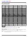
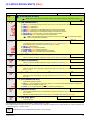
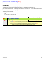
Software enhancements
Since the Altivar ATV 61 was first launched, it has benefited from the addition of several new functions. The software version is now V6.6.
Although this documentation relates to version V6.6, it can still be used with earlier versions.
The software version is indicated on the nameplate attached to the body of the drive.
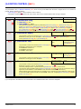
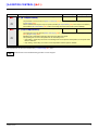
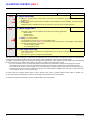
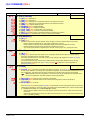
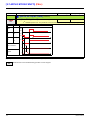
Enhancements made to version V1.2 in comparison to V1.1
New parameters and functions
Option of operating with a BACnet communication card
[1.8 FAULT MANAGEMENT] (FLt-) menu
• The external fault [EXTERNAL FAULT] (EtF-) page 199 can now be configured in positive or negative logic via [External fault config.]
(LEt).
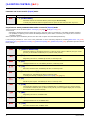
Enhancements made to version V1.4 in comparison to V1.2
Factory setting
Note: In versions V1.1 and V1.2, analog output AO1 was assigned to the motor frequency. In the new version, this output is not
assigned.
With the exception of this parameter, the factory setting of versions V1.1 and V1.2 remain the same in the new version. The new
functions are inactive in the factory setting.
New parameters and functions
[1.2 MONITORING] (SUP-) menu
Addition of states and internal values relating to the new functions described below.
[1.3 SETTINGS] (SEt-) menu
• [High torque thd.] (ttH) page 60
• [Low torque thd.] (ttL) page 60
• [Pulse warning thd.] (FqL) page 60
• [Freewheel stop Thd] (FFt) page 61
[1.4 MOTOR CONTROL] (drC-) menu
• Extension of the following configurations to all drive ratings (previously limited to 45 kW (60 HP) for ATV61pppM3X and to 75 kW
(100 HP) for ATV61
pppN4): synchronous motor [Sync. mot.] (SYn) page 69, sinus filter [Sinus filter] (OFI) page 77, noise reduction
[Noise reduction] (nrd) page 78
, braking balance [Braking balance] (bbA) page 80.
[1.5 INPUTS / OUTPUTS CFG] (I-O-) menu
• [AI net. channel] (AIC1) page 91
• New options for assigning relays and logic outputs, page 96: torque greater than high threshold, torque less than low threshold, motor
in forward rotation, motor in reverse rotation, measured speed threshold attained.
• Analog output AO1 can now be used as a logic output and assigned to relay functions and logic outputs, page 102
.
• New option of modifying the scale of analog outputs, page 104
, using the parameters [Scaling AOx min] (ASLx) and [Scaling AOx
max] (ASHx).
• New options for assigning analog outputs page 105
: signed motor torque and measured motor speed.
• New options for assigning alarm groups page 109
: torque greater than high threshold, torque less than low threshold, measured
speed threshold attained.

1760649 02/2014 7
Software enhancements
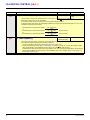
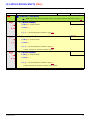
[1.7 APPLICATION FUNCT.] (Fun-) menu
• The summing, subtraction and multiplication reference functions can now be assigned to virtual input [Network AI] (AIU1) page 130.
• New parameter [Freewheel stop Thd] (FFt) page 135
used to adjust a threshold for switching to freewheel at the end of a stop on ramp
or fast stop.
• The torque limitation [TORQUE LIMITATION] (tOL-) page 166
can now be configured in whole % or in 0.1% increments using [Torque
increment] (IntP) and assigned to virtual input [Network AI] (AIU1).
• New Damper control function using the [DAMPER MANAGEMENT] (dAM-) menu, page 174
.
• Parameter switching [PARAM. SET SWITCHING] (MLP-) page 176
can now be assigned to attained frequency thresholds [Freq. Th.
attain.] (FtA) and [Freq. Th. 2 attain.] (F2A).
[1.8 FAULT MANAGEMENT] (FLt-) menu
• Option to reinitialize the drive without turning it off, via [Product reset] (rP) page 192.
• Option to reinitialize the drive via a logic input without turning it off, using [Product reset assig.] (rPA) page 192
.
• The option to configure the "output phase loss" fault [Output Phase Loss] (OPL) page 196
to [Output cut] (OAC) has been extended
to all drive ratings (previously limited to 45 kW (60 HP) for ATV61
pppM3X and 75 kW (100 HP) for ATV61pppN4).
• New monitoring function based on speed measurement using "Pulse input" input page 206
, via the [FREQUENCY METER] (FqF-)
menu.
• The braking unit short-circuit fault can now be configured using [Brake res. fault Mgt] (bUb) page 208
.
•The [Damper stuck] (Fd1) fault in the Damper control function can be configured via [DAMPER FAULT MGT.] (FdL-) page 213
.
[7 DISPLAY CONFIG.] menu
• Addition, in [7.4 KEYPAD PARAMETERS] page 239, of the [Keypad contrast] and [Keypad stand-by] parameters to adjust the contrast
and stand-by mode of the graphic display unit.
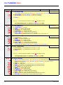
Enhancements made to version V1.5 in comparison to V1.4
Extension of the range with the addition of ATV61ppppY drives for 500 to 690 V supplies.
There are no new parameters, but the adjustment ranges and factory settings of some parameters have been adapted to the new voltages.
[1.5 INPUTS / OUTPUTS CFG] (I-O-) menu
Increased adjustment range for the relay and logic output delay parameters: 0 to 60000 ms instead of 0 to 9999 ms.
[1.7 APPLICATION FUNCT.] (Fun-) menu
• New parameter [Conf.sensor flow] (LnS) page 183, used to configure the zero flow sensor for positive or negative logic.
Enhancements made to version V1.6 in comparison to V1.5
The communication option card APOGEE FLN P1 (VW3 A3 314) is fully supported with the version V1.6 and above of the Altivar 61
software.
Enhancements made to version V1.8 in comparison to V1.6
[7 DISPLAY CONFIG.] menu
• Addition in [7.4 KEYPAD PARAMETERS] page 235 of [Power up menu].This parameter allows to choose the menu which displays on
the drive on power up.
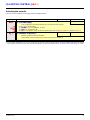
Enhancements made to version V2.1 in comparison to V1.8
[1.7 APPLICATION FUNCT.] (Fun-) menu
New parameters and functions
• New parameter [Regen. Conenction] (OIr) page 187. With this parameter it is possible to retun the braking energy to the mains.
• New parameter [Dis. operat opt code] (dOtd) page 136
.

8 1760649 02/2014
Software enhancements
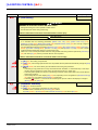
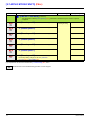
Enhancements made to version V5.8 in comparison to V2.1
Motor frequency range
The maximum output frequency has been limited to 599 Hz
[1.5 INPUTS / OUTPUTS CFG] (I-O-) menu
New parameter and function
New methods of assigning logic output, [R1 Assignment] (r1) page 97 : [Drive start] (Strt).
New factory setting
• [Motor control type] (Ctt) page 69 has been modified, [Energy Sav.] (nLd) to [V/F 2pts] (UF2).
• [IGBT test] (Strt) page 201
has been modified, [No] (nO) to [Yes] (YES).
• [Dis. operat opt code] (dOtd) page 136
has been modified, [Freewheel] (nSt) to [Ramp stop] (rMP).
[1.7 APPLICATION FUNCT.] (FUn-) menu
New parameter and function
• New parameter [Pmax Motor] (tPMM) page 167
• New parameter [Pmax Generator] (tPMG) page 167
Enhancements made to version V6.3 in comparison to V5.8
[1.7 APPLICATION FUNCT.] (FUn-) menu
New parameter and function
• New parameter [+/-Speed reference] (Srt) page 144
[1.8 FAULT MANAGEMENT] (FLt-) menu
New monitoring parameter [Freq. catch on fly] (FCAO) available with PC-Software, see [Catch on the fly] (FLr) page 194
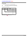
Enhancements made to version V6.6 in comparison to V6.3
[1.7 APPLICATION FUNCT.] (FUn-) menu
Switching frequency
The minimum adjustment range of [Switching freq.] (SFr) depends on the product caliber, see page 55.

1760649 02/2014 9
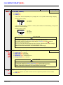
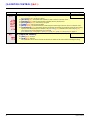
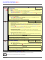
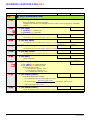
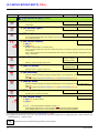
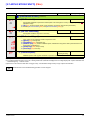
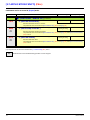
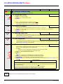
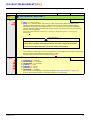
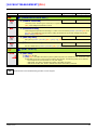
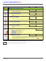
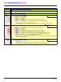
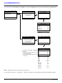
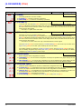
Steps for setting up the drive
INSTALLATION
v 1 Consult the Installation Manual
PROGRAMMING
Procedure applicable if the factory configuration, page 10, and use of the
[SIMPLY START] (SIM-) menu only are sufficient for the application.
b 2 Power up without run command
v If you are using a separate power supply
for the control section, follow the
instructions on page 11.
b 3 Select the language, if the drive
has a graphic display terminal
b 4 Configure the
[SIMPLY START] (SIM-) menu
v 2-wire or 3-wire control
v Macro configuration
v Motor parameters
) Perform an auto-tuning operation
v Motor thermal current
v Acceleration and deceleration
ramps
v Speed variation range
Tips:
• Before you start programming, complete
the user setting tables, page 248
.
• Perform an auto-tuning operation to
optimize performance, page 37
.
• If you get lost, return to the factory
settings, page 224
.
Note: Check that the wiring
of the drive is compatible with
its configuration.
b 5 Start

10 1760649 02/2014
Factory configuration
Drive factory settings
The Altivar 61 is factory-set for the most common operating conditions:
• Macro-configuration: Pumps/fans
• Motor frequency: 50 Hz
• Energy-saving variable torque applications
• Normal stop mode on deceleration ramp
• Stop mode in the event of a fault: freewheel
• Linear, acceleration and deceleration ramps: 3 seconds
• Low speed: 0 Hz
• High speed: 50 Hz
• Motor thermal current = rated drive current
• Standstill injection braking current = 0.7 x rated drive current, for 0.5 seconds
• No automatic starts after a fault
• Switching frequency 2.5 kHz or 12 kHz depending on drive rating
• Logic inputs:
- LI1: forward (1 operating direction), 2-wire control on transition
- LI2: inactive (not assigned)
- LI3: switching of 2
nd
speed reference
- LI4: fault reset
- LI5, LI6: inactive (not assigned)
• Analog inputs:
- AI1: 1
st
speed reference 0 +10 V
- AI2: 2
nd
speed reference 0-20 mA
• Relay R1: The contact opens in the event of a fault (or drive off)
• Relay R2: The contact closes when the drive is in operation
• Analog output AO1: 0-20 mA, inactive (not assigned)
If the above values are compatible with the application, the drive can be used without changing the settings.
Option card factory settings
The option card inputs/outputs are not factory-set.

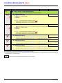
1760649 02/2014 11
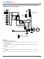
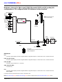
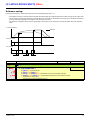
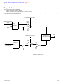
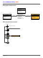
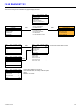
Setup – Preliminary recommendations
Turning on and configuring the drive
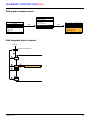
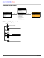
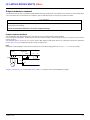
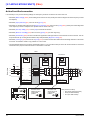
Separate control section power supply
Only supply power to the power section the next time the drive is powered up when:
A) The drive control section is powered independently of the power section (P24 and 0V terminals).
B) Whenever an option card is added or replaced.
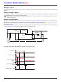
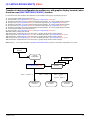
Power switching via line contactor
User adjustment and extension of functions
• The display unit and buttons can be used to modify the settings and to extend the functions described in the following pages.
• Return to factory settings is made easy by the [1.12 FACTORY SETTINGS] (FCS-) menu, see page 222
.
• There are three types of parameter:
- Display: Values displayed by the drive
- Adjustment: Can be changed during operation or when stopped
- Configuration: Can only be modified when stopped and no braking is taking place. Can be displayed during operation
DANGER
UNINTENDED EQUIPMENT OPERATION
• Before turning on and configuring the Altivar 61, check that the PWR (POWER REMOVAL) input is deactivated
(at state 0) in order to prevent unintended operation.
• Before turning on or on exiting the configuration menus, check that the inputs assigned to the run command are
deactivated (at state 0) since they can cause the motor to start immediately.
Failure to follow these instructions will result in death or serious injury.
CAUTION
INCOMPATIBLE LINE VOLTAGE
Before turning on and configuring the drive, ensure that the line voltage is compatible with the supply voltage range shown
on the drive nameplate. The drive may be damaged if the line voltage is not compatible.
Failure to follow these instructions can result in equipment damage.
CAUTION
RISK OF EQUIPMENT DAMAGE
• Avoid operating the contactor frequently (premature ageing of the filter capacitors).
• Cycle times < 60 s may result in damage to the pre-charge resistor.
Failure to follow these instructions can result in equipment damage.
DANGER
UNINTENDED EQUIPMENT OPERATION
• Check that changes made to the settings during operation do not present any danger.
• We recommend stopping the drive before making any changes.
Failure to follow these instructions will result in death or serious injury.

12 1760649 02/2014
Setup – Preliminary recommendations
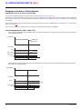
Starting
Important:
• In factory settings mode, the motor can only be supplied with power once the “forward”, “reverse” and “DC injection stop” commands
have been reset:
- On power-up or a manual fault reset or after a stop command
If they have not been reset, the drive will display “nSt” but will not start.
• If the automatic restart function has been configured ([Automatic restart] (Atr) parameter in the [1.8-FAULT MANAGEMENT] (FLt-)
menu, see page 193
), these commands are taken into account without a reset being necessary.
Test on a low power motor or without a motor
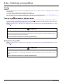
• In factory settings mode, [Output Phase Loss] detection (OPL) page 196 is active (OPL = YES). To check the drive in a test or
maintenance environment without having to switch to a motor with the same rating as the drive (particularly useful in the case of
high power drives), deactivate [Output Phase Loss] (OPL = no).
•Set [Motor control type] (Ctt) = [V/F 2pts] (UF2) or [V/F 5pts] (UF5) or [U/F Quad.] (UFq) ([1.4-MOTOR CONTROL] (drC-) menu,
see page 69
)
Using motors in parallel
•Set [Motor control type] (Ctt) = [V/F 2pts] (UF2) or [V/F 5pts] (UF5) or [U/F Quad.] (UFq) ([1.4-MOTOR CONTROL] (drC-) menu,
see page 69
)
CAUTION
UNINTENDED EQUIPMENT OPERATION
Motor thermal protection will not be provided by the drive if the motor current is less than 0.2 times the rated drive current.
Provide an alternative means of thermal protection.
Failure to follow these instructions can result in equipment damage.
CAUTION
UNINTENDED EQUIPMENT OPERATION
Motor thermal protection is no longer provided by the drive. Provide an alternative means of thermal protection on every
motor.
Failure to follow these instructions can result in equipment damage.

1760649 02/2014 13
Setup – Preliminary recommendations
ATV61pppY - Network which presents often under voltage
To assure an optimal running of an ATV61pppY used on network which presents often under voltage (network voltage contained between
425 V and 446 V), it is necessary to adjust [Prevention level] (UPL) = 383 V ([1.8-FAULT MANAGEMENT] (FLt-) menu, see page 201
).
Using motor with nominal voltage lower than drive supply voltage
• Configure [Vector Control 2pt] (UC2) = [Yes] (YES) ([1.4-MOTOR CONTROL] (drC-) menu, see page 71)
CAUTION
UNINTENDED EQUIPMENT OPERATION
• To protect a motor which has a nominal voltage lower than drive supply voltage, it is mandatory to use
[Vector Control 2pt] (UC2) function in order to limit maximal voltage of the motor lower than network voltage.
• Nevertheless, it is necessary to check that instantaneous voltage applied to the motor (link to DC bus voltage) are
compatible with characteristics of this one.
Failure to follow these instructions can result in equipment damage.

14 1760649 02/2014
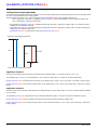
Graphic display terminal
Although the graphic display terminal is optional for low-power drives, it is a standard component on high-power drives (see catalog).
The graphic display terminal can be disconnected and connected remotely (on the door of an enclosure for example) using the cables and
accessories available as options (see catalog).
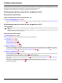
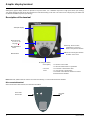
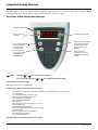
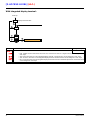
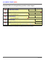
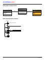
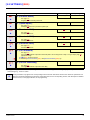
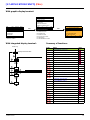
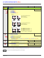
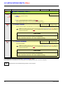
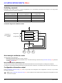
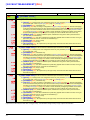
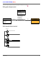
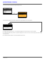
Description of the terminal
Note: Buttons 3, 4, 5 and 6 can be used to control the drive directly, if control via the terminal is activated.
Disconnected terminal
When the terminal is disconnected, two LEDs become visible:
1 Graphic display
2 Function keys
F1, F2, F3, F4,
see page 15
.
3 STOP/RESET
button
4 RUN button
5 Navigation button:
• Press (ENT): - To save the current value
- To enter the selected menu or parameter
• Turn CW/
CCW:
- To increment or decrement a value
- To go to the next or previous line
- To increase or decrease the reference if control
via the terminal is activated
7 ESC key: Aborts a value,
a parameter or a menu to
return to the previous selection
6 Button for reversing the direction
of rotation of the motor
HMI Modbus
Green LED:
DC bus ON
Red LED:
Fault

1760649 02/2014 15
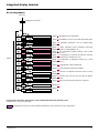
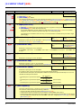
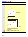
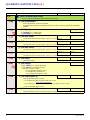
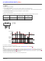
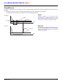
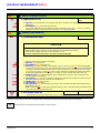
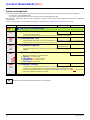
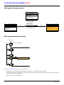
Graphic display terminal
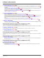
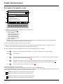
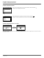
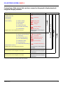
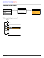
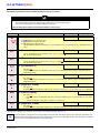
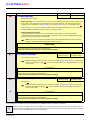
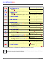
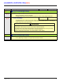
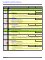
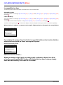
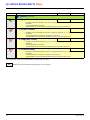
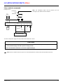
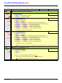
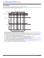
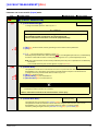
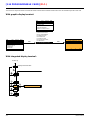
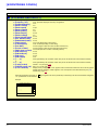
Description of the graphic screen
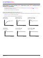
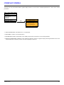
1. Display line. Its content can be configured; the factory settings show:
• The drive state (see page 16
)
• The active control channel:
- Term: Terminals
- HMI: Graphic display terminal
- MDB: Integrated Modbus
- CAN: Integrated CANopen
- NET: Communication card
- APP: Controller Inside card
• Frequency reference
• LOC/REM: “LOC” appears if the command and reference are set via the graphic display terminal; otherwise, “REM” appears.
This corresponds to the state selected by the [T/K] function key.
2. Menu line. Indicates the name of the current menu or submenu.
3. Menus, submenus, parameters, values, bar charts, etc., are displayed in drop-down window format on a maximum of 5 lines.
The line or value selected by the navigation button is displayed in reverse video.
4. Section displaying the functions assigned to the keys F1 to F4 and aligned with them, for example:
The function keys are dynamic and contextual.
Other functions (application functions) can be assigned to these keys via the [1.6 COMMAND] menu.
If a preset speed is assigned to a function key and if the function key is pressed, the motor will run at this preset speed until another preset
speed or JOG is pressed, speed reference is changed, or Stop key is pressed.
5. Indicates that there are no more levels below this display window.
Indicates that there are more levels below this display window.
6. Indicates that there are no more levels above this display window.
Indicates that there are more levels above this display window.
: Displays the code of the selected parameter, i.e., the code corresponding to the 7-segment display.
: Contextual help.
: Navigate horizontally to the left, or go to previous menu/submenu or, for a value, go to the next digit up, displayed
in reverse video (see the example on page 17
).
: Navigate horizontally to the right or go to next menu/submenu (going to the [2 ACCESS LEVEL] menu in this
example) or, for a value, go to the next digit down, displayed in reverse video (see the example on page 17
).
: Command and reference via the terminal, see page 122.
F1 F2 F3 F4
RDY Term +0.00 Hz REM
1 DRIVE MENU
1.1 SIMPLY START
1.2 MONITORING
1.3 SETTINGS
1.4 MOTOR CONTROL
1.5 INPUTS / OUTPUTS CFG
Code << >> T/K
1
2
3
4
6
5
• Code F1
•HELP F1
• << F2
• >> F3
• T/K F4

16 1760649 02/2014
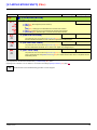
Graphic display terminal
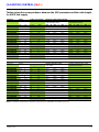
Drive state codes:
- ACC: Acceleration
- CLI: Current limit
- CTL: Controlled stop on input phase loss
- DCB: DC injection braking in progress
-DEC: Deceleration
- FLU: Motor fluxing in progress
- FRF: Drive at fallback speed
-FST: Fast stop
- NLP: No line power (no line supply on L1, L2, L3)
- NST: Freewheel stop
- OBR: Auto-adapted deceleration
- PRA: Power Removal function active (drive locked)
- RDY: Drive ready
- RUN: Drive running
- SOC: Controlled output cut in progress
- TUN: Auto-tuning in progress
- USA: Undervoltage alarm

1760649 02/2014 17
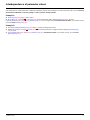
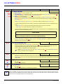
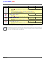
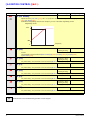
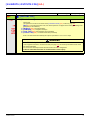
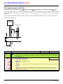
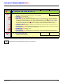
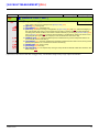
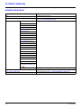
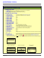
Graphic display terminal
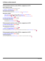
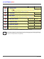
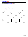
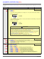
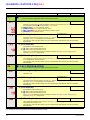
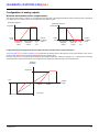
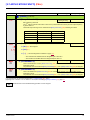
Example configuration windows:
Example configuration window for one value:
The << and >> arrows (keys F2 and F3) are used to select the digit to be modified, and the navigation button is rotated to increase or
decrease this number.
When only one possible selection can be made, the selection made is indicated by
Example: Only one language can be chosen.
When multiple selection is possible, the selections made are indicated by
Example: A number of parameters can be chosen to form the [USER MENU].
RDY Term +0.00 Hz REM
5 LANGUAGE
English
Français
Deutsch
Español
Italiano
<< >> T/K
Chinese
Turkish
Russian
PARAMETER SELECTION
1.3 SETTINGS
Ramp increment
Acceleration
Deceleration
Acceleration 2
Deceleration 2
Edit
RDY Term +0.00 Hz REM
Acceleration
9.51 s
Min = 0.01 Max = 99.99
<< >> T/K
>>
RDY Term +0.00 Hz REM
Acceleration
9.51 s
Min = 0.01 Max = 99.99
<< >> T/K

18 1760649 02/2014
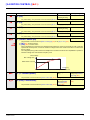
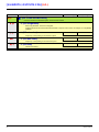
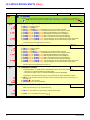
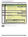
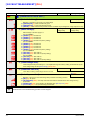
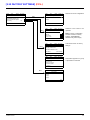
Graphic display terminal
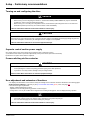
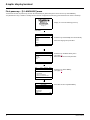
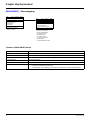
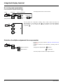
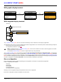
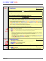
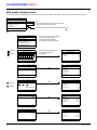
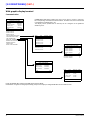
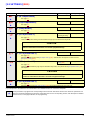
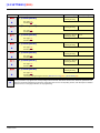
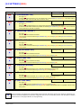
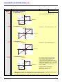
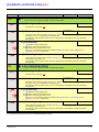
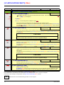
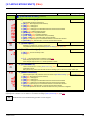
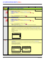
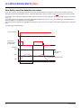
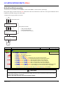
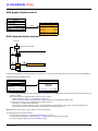
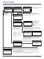
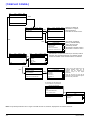
First power-up – [5. LANGUAGE] menu
The first time the drive is powered up, the user will automatically be guided through the menus as far as [1. DRIVE MENU].
The parameters in the [1.1 SIMPLY START] submenu must be configured and auto-tuning performed before the motor is started up.
Display for 3 seconds following power-up
3 seconds
Switches to [5 LANGUAGE] menu automatically.
Select the language and press ENT.
Switches to [2 ACCESS LEVEL] menu
(see page 27
)
Select the access level and press ENT.
Switches to [1 DRIVE MENU]
(see page 23
)
ESC
Press ESC to return to [MAIN MENU]
ATV61HU22N4
2.2kW/3HP 380/480V
Config. n°1
5 LANGUAGE
English
Français
Deutsch
Español
Italiano
Chinese
Turkish
Russian
RDY Term +0.00 Hz REM
2 ACCESS LEVEL
Basic
Standard
Advanced
Expert
RDY Term +0.00 Hz REM
1 DRIVE MENU
1.1 SIMPLY START
1.2. MONITORING
1.3. SETTINGS
1.4. MOTOR CONTROL
1.5. INPUTS / OUTPUTS CFG
Code << >> T/K
RDY Term +0.00 Hz REM
MAIN MENU
1 DRIVE MENU
2 ACCESS LEVEL
3 OPEN / SAVE AS
4 PASSWORD
5 LANGUAGE
Code T/K

1760649 02/2014 19
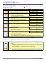
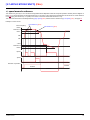
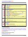
Graphic display terminal
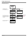
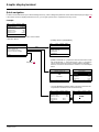
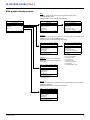
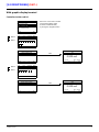
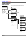
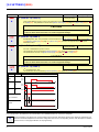
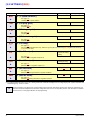
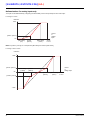
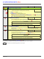
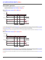
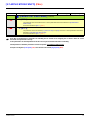
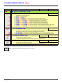
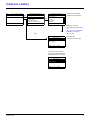
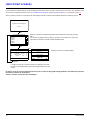
Subsequent power ups
3 seconds later, switches to
[1. DRIVE MENU] or to
[1.14 PROGRAMMABLE CARD].
If no operator inputs are made,
switches to "Display" automatically
10 seconds later (the display will
vary depending on the selected
configuration).
Users can return to [MAIN MENU]
by pressing ENT or ESC.
3 seconds
10 seconds
ESC
ATV61HU22N4
2.2kW/3HP 380/480V
Config. n°1
RDY Term +38Hz REM
1. DRIVE MENU
1.1 SIMPLY START
1.2 MONITORING
1.3 SETTINGS
1.4 MOTOR CONTROL
1.5 INPUTS / OUTPUTS CFG
Code << >> T/K
RDY Term +38Hz REM
Frequency ref.
Min=0 Max=60
T/K
RDY Term +38Hz REM
MAIN MENU
1 DRIVE MENU
2 ACCESS LEVEL
3 OPEN / SAVE AS
4 PASSWORD
5 LANGUAGE
Code T/K
38 Hz
RDY Term +0.00Hz REM
1.14 PROGRAMMABLE CARD
Modbus add Prg C. :17
DATE/TIME SETTINGS
<< >> T/K
RDY Term +0.00 Hz REM
1.3 SETTINGS
Ramp increment: 01
Acceleration 9.51 s
Deceleration: 9.67 s
Acceleration 2: 12.58 s
Deceleration 2: 13.45 s
Code << >> T/K
Menu selected in
[Power up menu]
page 239
ENT
or, if the Controller Inside card is present

20 1760649 02/2014
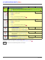
Graphic display terminal
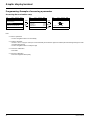
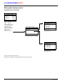
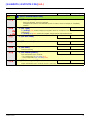
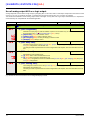
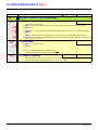
Programming: Example of accessing a parameter
Accessing the acceleration ramp
Note:
• To select a parameter:
- Turn the navigation button to scroll vertically.
• To modify a parameter:
- Use the << and >> keys (F2 and F3) to scroll horizontally and select the digit to be modified (the selected digit changes to white
on a black background).
- Turn the navigation button to modify the digit.
• To cancel the modification:
-Press ESC.
• To save the modification:
- Press the navigation button (ENT).
RDY Term +0.00 Hz REM
1 DRIVE MENU
1.1 SIMPLY START
1.2 MONITORING
1.3 SETTINGS
1.4 MOTOR CONTROL
1.5 INPUTS / OUTPUTS CFG
Code << >> T/K
ENT
ESC
RDY Term +0.00 Hz REM
1.3 SETTINGS
Ramp increment: 01
Acceleration 9.51 s
Deceleration: 9.67 s
Acceleration 2: 12.58 s
Deceleration 2: 13.45 s
Code << >> T/K
ENT
ENT or
ESC
RDY Term +0.00 Hz REM
Acceleration
9.51 s
Min = 0.01 Max = 99.99
<< >> T/K
Page is loading ...
Page is loading ...
Page is loading ...
Page is loading ...
Page is loading ...
Page is loading ...
Page is loading ...
Page is loading ...
Page is loading ...
Page is loading ...
Page is loading ...
Page is loading ...
Page is loading ...
Page is loading ...
Page is loading ...
Page is loading ...
Page is loading ...
Page is loading ...
Page is loading ...
Page is loading ...
Page is loading ...
Page is loading ...
Page is loading ...
Page is loading ...
Page is loading ...
Page is loading ...
Page is loading ...
Page is loading ...
Page is loading ...
Page is loading ...
Page is loading ...
Page is loading ...
Page is loading ...
Page is loading ...
Page is loading ...
Page is loading ...
Page is loading ...
Page is loading ...
Page is loading ...
Page is loading ...
Page is loading ...
Page is loading ...
Page is loading ...
Page is loading ...
Page is loading ...
Page is loading ...
Page is loading ...
Page is loading ...
Page is loading ...
Page is loading ...
Page is loading ...
Page is loading ...
Page is loading ...
Page is loading ...
Page is loading ...
Page is loading ...
Page is loading ...
Page is loading ...
Page is loading ...
Page is loading ...
Page is loading ...
Page is loading ...
Page is loading ...
Page is loading ...
Page is loading ...
Page is loading ...
Page is loading ...
Page is loading ...
Page is loading ...
Page is loading ...
Page is loading ...
Page is loading ...
Page is loading ...
Page is loading ...
Page is loading ...
Page is loading ...
Page is loading ...
Page is loading ...
Page is loading ...
Page is loading ...
Page is loading ...
Page is loading ...
Page is loading ...
Page is loading ...
Page is loading ...
Page is loading ...
Page is loading ...
Page is loading ...
Page is loading ...
Page is loading ...
Page is loading ...
Page is loading ...
Page is loading ...
Page is loading ...
Page is loading ...
Page is loading ...
Page is loading ...
Page is loading ...
Page is loading ...
Page is loading ...
Page is loading ...
Page is loading ...
Page is loading ...
Page is loading ...
Page is loading ...
Page is loading ...
Page is loading ...
Page is loading ...
Page is loading ...
Page is loading ...
Page is loading ...
Page is loading ...
Page is loading ...
Page is loading ...
Page is loading ...
Page is loading ...
Page is loading ...
Page is loading ...
Page is loading ...
Page is loading ...
Page is loading ...
Page is loading ...
Page is loading ...
Page is loading ...
Page is loading ...
Page is loading ...
Page is loading ...
Page is loading ...
Page is loading ...
Page is loading ...
Page is loading ...
Page is loading ...
Page is loading ...
Page is loading ...
Page is loading ...
Page is loading ...
Page is loading ...
Page is loading ...
Page is loading ...
Page is loading ...
Page is loading ...
Page is loading ...
Page is loading ...
Page is loading ...
Page is loading ...
Page is loading ...
Page is loading ...
Page is loading ...
Page is loading ...
Page is loading ...
Page is loading ...
Page is loading ...
Page is loading ...
Page is loading ...
Page is loading ...
Page is loading ...
Page is loading ...
Page is loading ...
Page is loading ...
Page is loading ...
Page is loading ...
Page is loading ...
Page is loading ...
Page is loading ...
Page is loading ...
Page is loading ...
Page is loading ...
Page is loading ...
Page is loading ...
Page is loading ...
Page is loading ...
Page is loading ...
Page is loading ...
Page is loading ...
Page is loading ...
Page is loading ...
Page is loading ...
Page is loading ...
Page is loading ...
Page is loading ...
Page is loading ...
Page is loading ...
Page is loading ...
Page is loading ...
Page is loading ...
Page is loading ...
Page is loading ...
Page is loading ...
Page is loading ...
Page is loading ...
Page is loading ...
Page is loading ...
Page is loading ...
Page is loading ...
Page is loading ...
Page is loading ...
Page is loading ...
Page is loading ...
Page is loading ...
Page is loading ...
Page is loading ...
Page is loading ...
Page is loading ...
Page is loading ...
Page is loading ...
Page is loading ...
Page is loading ...
Page is loading ...
Page is loading ...
Page is loading ...
Page is loading ...
Page is loading ...
Page is loading ...
Page is loading ...
Page is loading ...
Page is loading ...
Page is loading ...
Page is loading ...
Page is loading ...
Page is loading ...
Page is loading ...
Page is loading ...
Page is loading ...
Page is loading ...
Page is loading ...
Page is loading ...
Page is loading ...
Page is loading ...
Page is loading ...
Page is loading ...
Page is loading ...
Page is loading ...
Page is loading ...
Page is loading ...
Page is loading ...
Page is loading ...
Page is loading ...
Page is loading ...
Page is loading ...
Page is loading ...
Page is loading ...
Page is loading ...
Page is loading ...
Page is loading ...
Page is loading ...
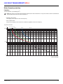
-
 1
1
-
 2
2
-
 3
3
-
 4
4
-
 5
5
-
 6
6
-
 7
7
-
 8
8
-
 9
9
-
 10
10
-
 11
11
-
 12
12
-
 13
13
-
 14
14
-
 15
15
-
 16
16
-
 17
17
-
 18
18
-
 19
19
-
 20
20
-
 21
21
-
 22
22
-
 23
23
-
 24
24
-
 25
25
-
 26
26
-
 27
27
-
 28
28
-
 29
29
-
 30
30
-
 31
31
-
 32
32
-
 33
33
-
 34
34
-
 35
35
-
 36
36
-
 37
37
-
 38
38
-
 39
39
-
 40
40
-
 41
41
-
 42
42
-
 43
43
-
 44
44
-
 45
45
-
 46
46
-
 47
47
-
 48
48
-
 49
49
-
 50
50
-
 51
51
-
 52
52
-
 53
53
-
 54
54
-
 55
55
-
 56
56
-
 57
57
-
 58
58
-
 59
59
-
 60
60
-
 61
61
-
 62
62
-
 63
63
-
 64
64
-
 65
65
-
 66
66
-
 67
67
-
 68
68
-
 69
69
-
 70
70
-
 71
71
-
 72
72
-
 73
73
-
 74
74
-
 75
75
-
 76
76
-
 77
77
-
 78
78
-
 79
79
-
 80
80
-
 81
81
-
 82
82
-
 83
83
-
 84
84
-
 85
85
-
 86
86
-
 87
87
-
 88
88
-
 89
89
-
 90
90
-
 91
91
-
 92
92
-
 93
93
-
 94
94
-
 95
95
-
 96
96
-
 97
97
-
 98
98
-
 99
99
-
 100
100
-
 101
101
-
 102
102
-
 103
103
-
 104
104
-
 105
105
-
 106
106
-
 107
107
-
 108
108
-
 109
109
-
 110
110
-
 111
111
-
 112
112
-
 113
113
-
 114
114
-
 115
115
-
 116
116
-
 117
117
-
 118
118
-
 119
119
-
 120
120
-
 121
121
-
 122
122
-
 123
123
-
 124
124
-
 125
125
-
 126
126
-
 127
127
-
 128
128
-
 129
129
-
 130
130
-
 131
131
-
 132
132
-
 133
133
-
 134
134
-
 135
135
-
 136
136
-
 137
137
-
 138
138
-
 139
139
-
 140
140
-
 141
141
-
 142
142
-
 143
143
-
 144
144
-
 145
145
-
 146
146
-
 147
147
-
 148
148
-
 149
149
-
 150
150
-
 151
151
-
 152
152
-
 153
153
-
 154
154
-
 155
155
-
 156
156
-
 157
157
-
 158
158
-
 159
159
-
 160
160
-
 161
161
-
 162
162
-
 163
163
-
 164
164
-
 165
165
-
 166
166
-
 167
167
-
 168
168
-
 169
169
-
 170
170
-
 171
171
-
 172
172
-
 173
173
-
 174
174
-
 175
175
-
 176
176
-
 177
177
-
 178
178
-
 179
179
-
 180
180
-
 181
181
-
 182
182
-
 183
183
-
 184
184
-
 185
185
-
 186
186
-
 187
187
-
 188
188
-
 189
189
-
 190
190
-
 191
191
-
 192
192
-
 193
193
-
 194
194
-
 195
195
-
 196
196
-
 197
197
-
 198
198
-
 199
199
-
 200
200
-
 201
201
-
 202
202
-
 203
203
-
 204
204
-
 205
205
-
 206
206
-
 207
207
-
 208
208
-
 209
209
-
 210
210
-
 211
211
-
 212
212
-
 213
213
-
 214
214
-
 215
215
-
 216
216
-
 217
217
-
 218
218
-
 219
219
-
 220
220
-
 221
221
-
 222
222
-
 223
223
-
 224
224
-
 225
225
-
 226
226
-
 227
227
-
 228
228
-
 229
229
-
 230
230
-
 231
231
-
 232
232
-
 233
233
-
 234
234
-
 235
235
-
 236
236
-
 237
237
-
 238
238
-
 239
239
-
 240
240
-
 241
241
-
 242
242
-
 243
243
-
 244
244
-
 245
245
-
 246
246
-
 247
247
-
 248
248
-
 249
249
-
 250
250
-
 251
251
-
 252
252
-
 253
253
-
 254
254
-
 255
255
-
 256
256
-
 257
257
-
 258
258
-
 259
259
-
 260
260
-
 261
261
-
 262
262
-
 263
263
-
 264
264
-
 265
265


Ask a question and I''ll find the answer in the document
Finding information in a document is now easier with AI
Related papers
-
Schneider Electric ATV71 Owner's manual
-
Schneider Electric ATV61/71 PROFINET Owner's manual
-
-
-
Schneider Electric ATV312 User manual
-
-
-
-
-
Other documents
-
Metro S08975 Operating instructions
-
Barco FR12 series Owner's manual
-
Eurotherm ATV71 Owner's manual
-
WEG MVW3000 Programming Manual
-
Sennheiser Speaker System LSP 500 PRO User manual
-
-
-
Amazon AN User manual
-
-
 WPI AirTherm ATX User manual
