Dell PowerVault 770N (Deskside NAS Appliance) User guide

Category
Servers
Type
User guide

This manual is also suitable for

Dellâ„¢ PowerVaultâ„¢ NAS Fibre Channel Cluster Systems
Installation and Troubleshooting Guide
Introduction
Preparing Your Systems for Clustering
Cabling Your Cluster Hardware
Installing Your Cluster in a Direct-Attached Environment
Installing Your Cluster in a SAN Environment
Maintaining Your Cluster
Using MSCS
Troubleshooting
Cluster Data Sheets
Abbreviations and Acronyms
NOTE: A NOTE indicates important information that helps you make better use of your computer.
NOTICE: A NOTICE indicates either potential damage to hardware or loss of data and tells you how to avoid the
problem.
CAUTION: A CAUTION indicates a potential for property damage, personal injury, or death.
Information in this document is subject to change without notice.
© 2003 Dell Inc. All rights reserved.
Reproduction in any manner whatsoever without the written permission of Dell Inc. is strictly forbidden.
Trademarks used in this text: Dell, the DELL logo, PowerEdge, PowerVault, and Dell OpenManage are trademarks of Dell Inc.; Microsoft, Windows,
Windows NT, and MS-DOS are registered trademarks of Microsoft Corporation; EMC, Navisphere, and PowerPath are registered trademarks and
Navisphere Manager, Access Logix, ControlCenter, MirrorView, SnapView, and SAN Copy are trademarks of EMC Corporation; Intel and Pentium are
registered trademarks of Intel Corporation.
Other trademarks and trade names may be used in this document to refer to either the entities claiming the marks and names or their products.
Dell Inc. disclaims any proprietary interest in trademarks and trade names other than its own.
Initial release: September 2003
Back to Contents Page
Introduction
Dellâ„¢ PowerVaultâ„¢ NAS Fibre Channel Cluster Systems Installation and Troubleshooting Guide
Intended Audience Configuring Active and Passive Cluster Nodes
Obtaining Technical Assistance Failover and Failback Support
Overview Failover Policies
NAS Fibre Channel Cluster Solution Minimum System Requirements
Optional Cluster Configurations Other Documents You May Need
This guide provides information for installing a Dellâ„¢ PowerVaultâ„¢ NAS Fibre Channel cluster solution in a corporate
enterprise running the Microsoft® Windows® Storage Server 2003, Enterprise Edition operating system (hereafter known as
NAS Manager).
The information in this guide includes:
Basic Fibre Channel cluster installation procedures, which include:
Preparing server and storage systems for clustering
Cabling the cluster configuration
Configuring the peripherals for the cluster, including the HBA and RAID controllers
Installation procedures for installing direct-attached and SAN attached cluster configurations in your corporate network
Cluster upgrading and maintenance procedures
Information about MSCS, the clustering software built into the Windows Storage Server 2003, Enterprise Edition
operating system
Troubleshooting procedures
Data sheets for recording critical cluster configuration information
Intended Audience
This guide was developed for experienced IT professionals who need to install, cable, and configure a NAS cluster solution in
an enterprise environment and for trained service technicians who perform cluster upgrade and maintenance procedures. This
guide also addresses readers who are new to clustering technology.
Obtaining More Information
See "Overview" for a general description of NAS clusters and clustering technology.
See "Using MSCS
" for an overview of the clustering software built into the Windows Storage Server 2003, Enterprise Edition
operating system.
Obtaining Technical Assistance
Dell Enterprise Training and Certification is available; see www.dell.com/training for more information. This service may
not be offered in all locations.
Overview
This section provides an overview of clustering and the major cluster components used in the Windows Server 2003,
Enterprise Edition operating system.
NOTE: In this guide, Microsoft Cluster Service for Windows Storage Server 2003, Enterprise Edition is also referred to
as MSCS.
Clustering
Clustering is the process of joining two or more NAS systems together to function as a single system. Using specific hardware
and software that is interconnected to work as a single entity, clustering provides an automatic failover solution to hardware
or software failures. If one of the clustered systems (also known as cluster nodes) fail for any reason, the user resources
running on the failed system are moved (or failed over) to one or more systems in the cluster by the MSCS software—the
failover software component in specific versions of the Windows operating system. When the failed system is repaired and
brought back online, user resources automatically transfer back to the repaired system or remain on the failover system,
depending on how MSCS is configured.
The availability of network services is critical to applications in a client/server environment. Clustering reduces the amount of
downtime caused by unexpected failures, providing maximum uptime of mission critical applications—also known as high
availability—that surpasses the capabilities of a stand-alone system. Using MSCS, clustering ensures that applications on a
failed cluster node continue on the remaining node by migrating and managing the required resource to the remaining node in
the cluster. Clusters that reduce the amount of system downtime are known as high-availability clusters.
Virtual Servers and Resource Groups
In a standard client/server environment, a user accesses a network resource by connecting to a physical server (such as a
NAS system) with a unique IP address and network name. If the server fails for any reason, the user will no longer be able to
access the resource. In a cluster environment, a user does not access a physical server, but a virtual server—a network
resource managed by MSCS.
Each virtual server, which is transparent to the user, has its own IP address, server name, and disk drive in the shared
storage system. MSCS manages the virtual server as a resource group, which contains a list of the cluster resources. Virtual
servers and resource groups are transparent to the network client.
See "Cluster Resources
" in "Using MSCS" for more information on network resources.
Virtual servers are designed to dynamically reconfigure user resources during a connection or hardware failure, providing a
higher availability of network resources as compared to a nonclustered NAS system. When MSCS detects a failed cluster node
or failed application, MSCS moves the entire virtual server resource group to another cluster node and remaps the virtual
server to the new network connection. The network client attached to an application in the virtual server will only experience
a momentary delay in accessing their resources while MSCS re-establishes a network connection to the virtual server. This
process of moving and restarting a virtual server on a healthy cluster node is called failover.
See "Groups
" in "Using MSCS" for more information on resource groups.
Failover and Failback
If one of the cluster nodes should fail for any reason, MSCS moves (or fails over) the virtual server to another cluster node.
After the cluster node is repaired and brought online, MSCS may move (or fail back) the virtual server to the original cluster
node, if required. This failover capability enables the cluster configuration to keep network resources and application programs
running on the network while the failed node is taken offline, repaired, and brought back online. The overall impact of a node
failure to network operation is minimal.
See "Failover and Failback
" in "Using MSCS" for more information.
EMC® PowerPath®, a software component that is installed on the cluster nodes and stand-alone systems, provides an I/O
path failover solution for the I/O traffic between the host system and the storage system. Each cluster node has redundant
paths to a storage system in the cluster. If a path between the cluster nodes and the shared storage system fails for any
reason, PowerPath reroutes the Fibre Channel I/O traffic to the remaining path(s). After the failed path is repaired, PowerPath
can resume network traffic on the original path.
NOTE: The NAS cluster solution requires EMC PowerPath.
See "Storage Management Software
" for more information about EMC PowerPath.
Quorum Resource
In every cluster, a single disk resource is designated as the quorum resource. This resource maintains the configuration data
necessary for cluster recovery when a cluster node fails. The quorum resource contains the details of all the changes that
have been applied to a cluster database.
The quorum resource can be any resource with the following attributes:
Enables a single node to gain and defend its physical control of the quorum resource.
For example, SCSI or Fibre Channel disks use reserve and release commands for arbitration.
Provides physical storage that is accessible by any node in the cluster.
Uses the NTFS file system.
See "Quorum Resource
" in "Using MSCS" and the MSCS online documentation for more information.
NOTE: NAS Fibre Channel clusters do not support the Majority Node Set Quorum resource type.
Shared Storage Systems
In MSCS cluster configurations, Fibre Channel provides the means for the cluster nodes to share access to one or more
external storage systems. However, only one of the cluster nodes—one of the servers in the cluster—owns any RAID volume
in the external storage system at any point in time. The Cluster Service maintains control over which node has access to each
RAID volume in the shared storage system.
See "Fibre Channel Protocol
" for more information on Fibre Channel storage systems.
NOTE: The Access Logixâ„¢ software is required when the storage system is connected to two or more clusters, two or
more nonclustered systems, or a combination of both clustered and nonclustered systems. Access Logix software is not
required for one stand-alone system or single cluster configurations.
Each storage system in the cluster is centrally managed by one host system (also called a management station) running EMC
ControlCenter™ Navisphere Manager™—a storage management application used to configure Dell | EMC storage systems.
Navisphere Manager provides centralized storage management and configuration from a single management console. Using a
graphical user interface (GUI), you can select a specific view of your storage arrays, as shown in Table 1-1
.
Table 1-1. Navisphere Manager Storage Views
View Description
Storage Shows a "map" of the hardware configuration to identify hardware faults and shows the logical storage
components and their relationships to each other.
Host Shows the host system's storage group and attached LUNs.
Monitors Shows all Event Monitor configurations. These configurations include centralized and distributed monitoring
configurations.
You can use Navisphere Manager to perform multiple tasks, such as creating RAID groups, binding LUNs, and downloading
firmware. Combined with Access Logix, administrators can manage and control data access across multiple heterogeneous
hosts in distributed SANs.
Optional software for the shared storage systems include:
EMC MirrorView™ — Provides synchronous mirroring between two storage systems in a campus environment.
EMC SnapView™ — Captures point-in-time images of a LUN for backups, decision support, or testing without affecting
the contents of the source LUN.
EMC SAN Copy — Moves data between Dell | EMC storage systems without using host CPU cycles or LAN bandwidth.
See "Installing and Configuring the Shared Storage System
" for more information about Navisphere Manager, Access Logix,
MirrorView, SnapView, and SAN Copy.
See "Shared Storage Systems
" for a description of the shared storage systems for the NAS cluster solution.
NAS Fibre Channel Cluster Solution
The NAS Fibre Channel cluster solution implements two-node clustering technology based on the MSCS software incorporated
within the Windows Storage Server 2003, Enterprise Edition operating systems. This cluster solution provides the following
benefits in meeting the needs of mission-critical network application programs:
2 Gb/s Fibre Channel technology
High availability of system services and resources to network clients
Redundant storage for application program data
Failure recovery for cluster application programs
Flexible maintenance capabilities, allowing you to repair, maintain, or upgrade a cluster node or cluster storage system
without taking the entire cluster offline
Each cluster node is configured with software, storage, and network resources that enable it to monitor and interact with the
other nodes to provide mutually redundant operation. If a cluster node fails for any reason, virtual servers and resources
groups running client resources are failed over to other healthy cluster nodes. When the failed node is repaired and brought
back online, the virtual servers and resource groups are failed back to the repaired node (if desired).
The cluster nodes, therefore, operate as a single resource, rather than a collection of individual systems. Because the cluster
nodes interact in this way, they appear as a single system to the network clients.
Storage System
NAS Fibre Channel clusters support the Dell | EMC CX200, CX400, and CX600 systems—modular 2-Gb/s Fibre Channel storage
systems that provide scalable storage solutions in a direct-attached or SAN-attached environment.
These storage systems consist of multiple hardware components that work together as a single system. These components
include:
Processor enclosure (DPE or SPE)
Disk array enclosure (DAE2)
Standby power supply
Host bus adapter
Processor Enclosure
The processor enclosure is configured with storage processors that control the RAID arrays in the storage system and provide
various storage functionalities, such as snapshots, LUN masking, and remote mirroring.
The CX200 and CX400 are DPEs and are configured with internal hard drives. The CX600 is a storage processor enclosure
(SPE) and is not configured with internal hard drives. For primary storage, the SPE must be attached to one or more 2-Gb/s
DAEs. The DPE and SPE are controlled by the core software (FLARE), which hosts the Navisphere® management software and
manages the workload between the storage processors and the hard drives.
The SPE requires two standby power supplies (SPS) to provide backup power to the SPE storage processors and the first
DAE2 or DAE2-Operating System (DAE2-OS) enclosure that is connected to the SPE. If a power failure occurs on the SPE, the
backup power allows the SPE to transfer unprocessed write cache to the DAE2 vault disks before it shuts down, thereby
preventing data loss. See Table 1-13
in for additional information.
NOTE: The DAE2 and DAE2-OS are 2-Gb/s DAE enclosures. The DAE2-OS enclosure is the first DAE2 enclosure that is
connected to the CX600 and has the core software (FLARE) preinstalled on the first five hard drives. These first five
hard drives are called the vault disks.
The processor enclosure includes the following features:
Two to four 2-Gb/s front-end ports per storage processor, providing redundant paths to the storage system. If one of
the paths fail for any reason, the data is routed through the redundant path until the failed path is repaired.
EMC ControlCenter Navisphere management software for storage system management, including:
SnapView (for point-in-time data copies)
MirrorView (for remote synchronous data mirroring)
SAN Copy (for moving data between Dell | EMC storage systems)
NOTE: The CX200 does not support SnapView and Mirrorview.
Supports nondisruptive upgrades for software and firmware.
Storage for multiple clustered and nonclustered hosts.
Supports RAID 0, 1, 1/0, 3, and 5.
Compatible with the Dell | EMC FC4700 and FC4700-2 storage systems as a MirrorView target or source.
NOTICE: The hardware components in the processor enclosures are not compatible with the components in the Dell |
EMC FC4500, FC4700, and FC4700-2 DAEs. Exchanging components between these enclosures could damage the
enclosures and void your warranty.
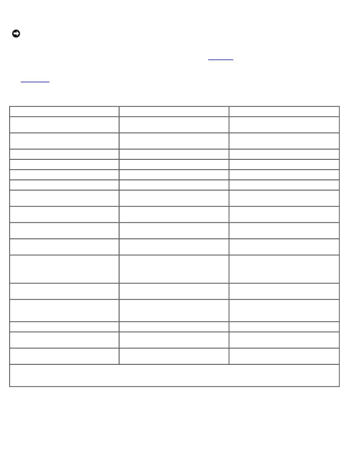
The supported processor enclosures vary in performance and configuration. Table 1-2
provides the features for each
processor enclosure.
See Table 1-13
in for more information on the supported processor enclosures.
Table 1-2. Processor Enclosure Features
CX200 CX400 CX600
3-U entry-level modular storage
system.
3-U midrange modular storage system. 4-U enterprise modular storage system.
Two Intel® 800-MHz Mobile Pentium®
III processors.
Two Intel 800-MHz Pentium III
processors.
Two Intel 2-GHz Pentium 4 processors.
1-GB cache. Up to 2-GB cache. Up to 8-GB cache.
Supports up to 15 HBAs per SP. Supports up to 15 HBAs per port Supports up to 32 HBAs per port.
Up to 200-MB/s data transfer rate. Up to 680-MB/s data transfer rate. Up to 1300-MB/s data transfer rate.
Supports up to 15 internal hard drives. Supports up to 15 internal hard drives. No internal hard drive support.
Two front-end ports in a hub
configuration that connect to the hosts.
Four front-end ports that connect to the
hosts.
Eight front-end ports that connect to
the hosts.
Two back-end ports that connect to
disks through the DAE2 enclosures.
Four back-end ports that connect to
disks through the DAE2 enclosures.
Four back-end ports that connect to
disks through the DAE2 enclosures.
Supports one DAE2 enclosure for
additional data storage.
Supports up to three DAE2 enclosures
for additional data storage.
Supports up to 16 DAE2 enclosures for
additional storage.
Supports one cluster in a direct-
attached cluster configuration.
Supports one cluster in a direct-
attached cluster configuration.
Supports up to two clusters in a direct-
attached cluster configuration.
Up to 30 drives per array with a
maximum storage capacity of 4.4 TB
(using fifteen 1-inch 146-GB hard
drives for each DAE2 enclosure).
Up to 60 drives per array with a
maximum storage capacity of 8.8 TB
(using fifteen 1-inch 146-GB hard
drives for each DAE2 enclosure).
Up to 240 drives per array with a
maximum storage capacity of 35 TB
(using fifteen 1-inch 146-GB hard drives
for each DAE2 enclosure).
Manages the RAID arrays on the DPE
and the DAE2.
Manages the RAID arrays on the DPE
and the DAE2.
Manages the RAID arrays on the DAE2.
Core software (FLARE) and vault disks
are located on the first five internal
hard drives.
Core software (FLARE) and vault disks
are located on the first five internal hard
drives.
Core software (FLARE) and vault disks
are located on the first attached DAE2
(or DAE2-OS).
Supports RAID 0, 1, 1/0, 3, and 5. Supports RAID 0, 1, 1/0, 3, and 5. Supports RAID 0, 1, 1/0, 3, and 5.
Supports nondisruptive upgrades for
online software and firmware.
Supports nondisruptive upgrades for
online software and firmware.
Supports nondisruptive upgrades for
online software and firmware.
No support for MirrorView, SnapView,
and SAN Copy.
Supports MirrorView, SnapView, and
SAN Copy.
Supports MirrorView, SnapView, and
SAN Copy.
NOTE: The core software (FLARE) contains the operating system that powers the storage system. The vault disks are the
first five hard drives in the DPE (CX200 and CX400) or the first attached DAE2 (CX600) that store unprocessed write cache
if the storage system power sources fail.
Disk Array Enclosure
The NAS cluster solution uses the DAE2—a 2-Gb/s, 3-U DAE that can be configured with up to 15 dual-ported, hot-
swappable Fibre Channel hard drives per enclosure. The DAE2 provides a scalable storage solution, allowing you to add
additional hard drives to the enclosure as needed.
The DAE2 is also available as the DAE2-OS—a DAE2 enclosure with the core software (FLARE) preinstalled on the first five
hard drives that provides both the primary storage and the operating system for the CX600 storage system.
Additional features include:
2-Gb/s Fibre Channel data transfer rate
Maximum capacity of fifteen 1-inch 146-GB hard drives
Redundant hot-swappable power supplies, cooling fan assemblies, and link control cards (LCCs)
Table 1-3
lists the number of supported DAE2 enclosures for each storage system.
Table 1-3. Supported DAE2 Enclosures
Storage System Supported DAE2 Enclosures
CX200 One
CX400 Up to 3
CX600 Up to 16
.
SPS
The SPS is a 1-U power supply that provides backup power to the processor enclosures or the CX600 SPE and its first DAE2
(or DAE2-OS) enclosure. The storage system requires two SPSs, with each SPS connected to a separate power source for
redundancy. If both power sources fail, the SPSs enable the SPE to flush the write cache to the vault drives. When the power
is restored, the SPE writes the cache content in the vault drives back to the cache. This method ensures that the SPE cached
data is not lost during a power failure.
Each SPS is hot-swappable, and two 1000-W DC SPSs are required for the following:
CX200 — DPE
CX400 — DPE
CX600 — SPE and its first DAE2-OS enclosure
The SPS installs in the SPS rack kit below the SPE.
NOTICE: To avoid data loss, do not disconnect any power or SPS cables or turn off the CX200 DPE, CX400 DPE, CX600
SPE, or DAE2 power supplies during normal operation. If you need to shut down the SPE, DPE, or DAE2 enclosure(s),
stop all I/O to the storage system, stop the Cluster Service, and then shut down all the host systems attached to the
storage systems. After you perform these procedures, turn off the SPS devices by using their power switches.
HBA
The HBA is an I/O adapter that connects the server's PCI bus to the storage components. Two HBAs must be installed in each
server in the SAN to manage the I/O data transfer from the server to the storage system. See the Platform Guide for a list of
supported HBAs.
Fibre Channel Switch
The Fibre Channel switch functions as a director, mapping requests and responses between the interconnected devices and
provides a dedicated interconnection between the server and storage system. See the Platform Guide for a list of supported
Fibre Channel switches.
NOTE: The Dell | EMC DS-24M2 (McData Spherion 4500) Fibre Channel switch supports Flexport configurations, which
allows you to vary the number of active switch ports. Flexport configuration is dependent on firmware license key and
the appropriate number of SFP modules. When you update the firmware license key, you are provided with the
appropriate number of SFP modules and a new key that allows you to access additional ports on the switch.
Hardware and Software Technologies
The NAS cluster solution implements the following hardware and software technologies:
Clustering technology based on the MSCS software in the Windows Storage Server 2003, Enterprise Edition operating
system
Fibre Channel protocol
Fibre Channel switch fabric
Zones
SAN components
Storage management software
Clustering Technology
Clustering is the process of connecting multiple servers together to achieve higher availability and performance. MSCS is a
software component that is included with the Windows Storage Server 2003, Enterprise Edition operating system that
provides failover support for applications and services running on each node.
See "Using MSCS
" for more information on the Cluster Service.
NOTE: MSCS and NLB features cannot co-exist on the same cluster node, but can be used together in a multitiered
cluster configuration. For more information, see the Dell PowerEdge Clusters website located at
www.dell.com/clusters or the Microsoft website located at www.microsoft.com.
Fibre Channel Protocol
Fibre Channel is a scalable, high-performance data communications technology that allows multiple server systems to share
one or more storage systems. Unlike the SCSI technology, which is limited to short-distance connections and direct-attached
storage, Fibre Channel provides long-distance connectivity and the high bandwidth needed for transferring data between the
cluster nodes and the shared storage devices in a NAS cluster. By employing long-wave fiber optic cable between cascaded
switches, systems up to 10 km from the shared storage array can access data as if they are directly attached.
Implementing Fibre Channel technology in the NAS cluster provides you with the following advantages:
Flexibility — Fibre Channel implements both copper and optical cabling, allowing a distance of up to 10 kilometers
between switches without signal degradation.
Availability — Fibre Channel components implement redundant connections, providing multiple data paths and greater
availability for network clients.
Connectivity — Fibre Channel allows you to connect more devices to each other than SCSI. Because Fibre Channel
devices are hot-pluggable, you can add or remove devices from the cluster nodes without bringing down the cluster.
NAS Fibre Channel clusters support 2-Gb Fibre Channel, which provides high-speed data transfer between the cluster nodes
and storage systems and supports the smaller SFP connectors for higher port density.
Fibre Channel Switch Fabric
A Fibre Channel switch fabric consists of one or more Fibre Channel switches that provide high-speed connections between
servers and storage devices. The switches in a Fibre Channel fabric provide a connection through inbound and outbound
points from one device (sender) to another device or switch (receiver) on the network. If the data is sent to another switch,
the process repeats itself until a connection is established between the sender and the receiver.
Fibre Channel switches are linked together using ISLs. These ISLs use two Fibre Channel ports to connect the switches
together. Fibre Channel fabrics provide you with the ability to set up barriers between different devices and operating
environments. These barriers create logical fabric subsets with minimal software and hardware intervention. Similar to VLANs
in the client/server network, logical fabric subsets divide a fabric into smaller groups or components, regardless of their
proximity to one another. The logical subsets that form these barriers are called zones.
Zones
Zones help to segment a SAN into logical fabric subsets by setting up barriers between different operating environments with
minimal software and hardware intervention. Similar to subnets in the client/server network, these logical fabric subsets (or
zones) divide a fabric into smaller groups or components, regardless of their proximity to one another. By implementing
switch zoning together with Access Logix, you can attach multiple clusters or a combination of clusters and stand-alone
systems to a SAN.
NOTE: Dell supports only single-initiator zoning for connecting NAS clusters to the CX200, CX400, and CX600 storage
systems in a switched environment. A separate zone is created for each HBA, which includes the HBA and one or more
SP ports on the storage systems.
SAN
Cluster nodes attach to the storage systems through a cable connection (using a direct-attached configuration) or through a
SAN—a high-performance network storage solution. Similar to a LAN, a SAN is used to move data between servers and
storage systems, providing a high-speed storage resource for your cluster nodes. Using a specific collection of hardware and
software releases set to specific version levels, a SAN bypasses traditional network bottlenecks, providing a high-speed,
highly available data consolidation solution for your NAS systems.
See the EMC Support Matrix located in the EMC Technical Library at www.emc.com and the Platform Guide included with
your system documentation located at the Dell Support website at support.dell.com for the latest firmware and software
requirements.
SAN Components
Table 1-4 lists the key hardware and software components in a SAN.
NOTE: Your SAN may require additional hardware and software components that are not previously listed. See the
EMC Support Matrix located in the EMC Technical Library at www.emc.com for information about SAN-compliant
hardware and software components.
Table 1-4. SAN Components
Component Description
HBA Connects the cluster node's PCI bus to the storage system.
Storage system Provides external storage for the host systems (cluster nodes and stand-alone systems). Supported
storage systems include tape libraries, DAEs, and SPEs.
SAN storage
management software
Provides centralized control of the SAN for easier management. These software management tools
include:
Navisphere Agent
Navisphere Manager
EMC PowerPath
Access Logix (optional)
MirrorView (optional)
SnapView (optional)
Backup software (optional)
SAN Copy (optional)
See "Storage Management Software
" for a description of these software management tools.
Fibre Channel switch
(optional)
Provides a communications link between the servers, storage systems, and tape libraries.
Fabric (optional) One or more switches, which may be connected together using interswitched links.
Storage Management Software
NAS clusters require additional software components to manage the communications between the cluster nodes and the
storage systems in a SAN environment.
Table 1-5
provides a list of Navisphere and Dell OpenManageâ„¢ software packages that are used in NAS cluster configurations.
See "Minimum System Requirements
" for the storage management software required for your particular cluster configuration.
Table 1-5. Storage Management Software
Software Function
EMC
PowerPath
Detects and re-establishes a failed connection to a processor enclosure caused by a communication failure,
such as a failed storage processor, SP port, link control card (LCC), HBA, switch, or fiber optic cable. Without
human intervention, PowerPath can automatically reroute the I/O through an alternate path when a failure
occurs to provide connectivity for running applications.
Additional features include:
Dynamic load balancing
Multiple path detection
Navisphere
Manager
Provides centralized storage management and configuration from a single management console. Using a GUI,
Navisphere Manager allows you to configure and manage the disks and components in one or more shared
storage systems.
Additional features include:
Creating, binding, and unbinding LUNs
Changing configuration settings
Monitoring storage systems
Navisphere Manager is installed on the Dell | EMC storage systems or a host system that has network access
to the storage system.
Navisphere
Agent
Provides an interface between the host systems and the Dell | EMC storage system, allowing Navisphere
Manager to send and receive information to and from the storage system connected to a host system.
Access
Logix
(optional)
Allows multiple cluster nodes and servers to share a Fibre Channel shared storage system. Access Logix
restricts server access to specific volumes on a shared Dell | EMC storage system and protects your data from
unauthorized access.
Access Logix is required when the storage system is connected to two or more clusters, two or more
nonclustered systems, or a combination of both clustered and nonclustered systems.
MirrorView
(optional)
Automatically duplicates primary storage system data for a cluster or stand-alone system to a secondary
storage system in a campus environment. MirrorView implements synchronous mirroring, which ensures that
data is updated on both the primary and secondary storage systems at the same time. You can manage up to
100 mirrors per array or 50 mirrors if the Write Intent Log is initiated.
MirrorView is an optional software component that is installed on the storage processors as a nondisruptive
upgrade and is transparent to users and software applications. MirrorView can be used in conjunction with
SnapView and is managed from within Navisphere Manager.
SnapView
(optional)
Captures point-in-time images of a LUN and retains the image independently of subsequent changes to the
files. SnapView images can be used to make shared LUNs available to another system for backups, decision
support, or testing without affecting the contents of the source LUN.
SnapView captures LUN images in one of two formats:
Snapshot — A point-in-time image of the source LUN. Snapshots can be accessed by cluster nodes from
a different cluster or stand-alone systems as an additional mountable disk volume (or LUN) with
read/write access privileges. You can create up to 100 individual snapshots or up to eight snapshots of
the same source LUN. You can create up to 100 individual clones or up to eight clones of the same
source LUN.
Clone — A static image of the original source LUN. Clones can be used to restore corrupted LUNs and
migrate LUNs between RAID groups and SPs, allowing you to fine tune your RAID arrays.
NOTE: Each snapshot or clone must be accessed from a different host.
SnapView is an optional software component that is installed on the DPE or SPE storage processors as a
nondisruptive upgrade and is transparent to users and software applications. SnapView can be used in
conjunction with MirrorView and is managed from within Navisphere Manager.
SAN Copy
(optional)
Allows you to move data between Dell | EMC storage systems without using host processor cycles or LAN
bandwidth.
SAN Copy is an optional software component that is installed on the storage processors as a nondisruptive
upgrade and is transparent to users and software applications. SAN Copy can be used in conjunction with
SnapView or MirrorView and is managed from within Navisphere Manager.
Optional Cluster Configurations
Direct-attached cluster
SAN-attached cluster
The following sections provide detailed information and examples for these options.
Direct-Attached Cluster
In a direct-attached cluster configuration, both nodes of the cluster are directly attached to a single storage system. In this
configuration, the RAID controllers (or storage processors) on the storage systems are connected by cables directly to the
Fibre Channel HBAs in the cluster nodes.
NOTE: A direct-attached cluster configuration does not use a SAN.
Figure 1-1
shows a basic direct-attached, single cluster configuration for a NAS Fibre Channel cluster configuration.
Figure 1-1. Direct-Attached, Single Cluster Configuration
Using EMC PowerPath in a Direct-Attach Cluster
EMC PowerPath provides failover capabilities and multiple path detection as well as dynamic load balancing between multiple
ports on the same SP. Direct-attached clusters supported by Dell connect to a single port on each SP in the storage system.
Because of the single port limitation, PowerPath can only provide failover protection in a direct-attached configuration.
SAN-Attached Cluster
In a SAN-attached cluster configuration, all of the cluster nodes are attached to a single storage system or to multiple
storage systems through a SAN using a redundant switch fabric. SAN-attached cluster configurations are superior to direct-
attached cluster configurations in configuration flexibility, expandability, and performance.
See "Fibre Channel Switch Fabric
" for more information on Fibre Channel switch fabrics.
Figure 1-2
shows a SAN-attached cluster configuration.
Figure 1-2. SAN-Attached Cluster Configuration
Configuring Active and Passive Cluster Nodes
Cluster configurations may include both active and passive cluster nodes. Active nodes are the primary nodes in the cluster.
These nodes support the cluster workload by processing application requests and providing client services. Passive nodes are
backup nodes that support the active nodes if a hardware or software failure occurs, ensuring that client applications and
services are highly available.
NOTE: Passive nodes must be configured with the appropriate processing power and storage capacity to support the
resources that are running on the active nodes.
An active/active (active
x
) configuration is a cluster with virtual servers running separate applications or services on each
node. When an application is running on node 1, the remaining cluster node does not have to wait for node 1 to fail. The
remaining cluster node can run its own cluster-aware applications (or another instance of the same application) while
providing failover capabilities for the resources on node 1. This configuration requires careful planning to ensure that adequate
resources are available on each node to handle the increased load if one node fails.
An active/passive (active
x
/passive
x
) configuration is a cluster where an active cluster node is processing requests for a
clustered application while the passive cluster node simply waits for the active node to fail. For example, N + I failover
(where N = the number of active nodes and I = the number of inactive [or passive] nodes) is an active/passive failover policy
where a dedicated, passive cluster node provides backup for the active cluster node.
Active/passive configurations are more costly in terms of price and performance because the passive cluster node remains idle
all of the time. This configuration is appropriate for business-critical systems because the application can use all of the
resources of a standby cluster node if one active cluster node fails.
Table 1-6
provides a description of some active/passive configuration types.
Table 1-6. Active/Passive Configuration Types
Configuration
Type
Active Cluster
Node(s)
Passive Cluster
Node(s)
Description
Active
1
/Passive
1
1 1 The active node(s) processes requests while the passive node
waits for the active node to fail.
Active
2
/Passive
1
2 1
Active
2
/Passive
2
2 2
Active
3
/Passive
1
3 1
Active
3
/Passive
2
3 2
Active
4
/Passive
1
4 1
Active
4
/Passive
2
4 2
Active
5
/Passive
1
5 1
Active
5
/Passive
2
5 2
Active
6
/Passive
1
6 1
Active
6
/Passive
2
6 2
Active
7
/Passive
1
7 1
Failover and Failback Support
One of the key features of Cluster Service is failover and failback support. Failover is the process of automatically moving
resources from a failed cluster node to another cluster node. Failback is the process of moving the resources back to the
original cluster node (if required). Failback can be an automatic or manual process, depending on how you configure the
Cluster Service.
Failover Policies
When implementing a failover policy, configure failback if the cluster node lacks the resources (such as memory or processing
power) to support one or more cluster node failures.
Windows Storage Server 2003, Enterprise Edition Cluster
Configurations
NAS cluster configurations running Windows Storage Server 2003, Enterprise Edition provides the following failover policies:
N + I failover
Failover pair
Multiway failover
Failover ring
N + I Failover
N + I failover (where N = the number of active nodes and I = the number of inactive [or passive] nodes) is an active/passive
failover policy where dedicated, passive cluster node(s) provide backup for the active cluster node(s). This failover solution
provides the best solution for critical applications that require dedicated server resources. However, the backup cluster nodes
add a higher cost of ownership to the cluster because they remain idle and do not provide the cluster with additional network
resources.
Figure 1-3
shows an example of a 6 + 2 (N + I) failover configuration with six active nodes and two passive nodes. Table 1-7
provides an N + I failover configuration matrix for Figure 1-3.
Figure 1-3. Example of an N+I Failover Configuration for an Eight-Node Cluster
.
Table 1-7. Example of an N+I Failover Configuration for an Eight-Node Cluster
Cluster Resource Group Primary Node AntiAffinityClassNamesValue
A Node 1 AString
B Node 2 AString
C Node 3 AString
D Node 4 AString
E Node 5 AString
F Node 6 AString
Configuring Group Affinity
On N + I (active/passive) failover clusters running Windows Storage Server 2003, Enterprise Edition, some resource groups
may conflict with other groups if they are running on the same node. For example, running more than one Microsoft Exchange
virtual server on the same node may generate application conflicts. Using Windows Storage Server 2003, Enterprise Edition,
you can assign a public property (or attribute) to a dependency between groups to ensure that they failover to similar or
separate nodes. This public property is called group affinity.
Group affinity uses the AntiAffinityClassNamesValues public property, which ensures that designated cluster resources are
running on separate nodes, if possible.
For example, in Table 1-7
, the AntiAffinityClassNamesValues string for cluster resource group A and group B are identical
(AString), which indicates that these groups are assigned to run on separate cluster nodes, if possible. If node 1 fails, cluster
resource group A will failover to the next backup node (node 7). If node 2 then fails, because their
AntiAffinityClassNamesValues string value (AString) identifies group A and group B as conflicting groups, group B will skip
node 7 and instead fail over to node 8.
To set the public property for the cluster groups shown in Table 1-7:
1. Open a command prompt.
2. Type the following:
cluster group "A" /prop AntiAffinityClassNames="AString"
3. Repeat step 2
for the remaining cluster groups.
Use the "Cluster Data Sheets
" to configure group affinity in your N + I cluster configuration.
Failover Pair
Failover pair is a failover policy in which each application is allowed to failover between two specific nodes in a multinode
cluster. The Possible Owners List in Cluster Administrator is used to determine which nodes will run the failover applications.
This solution is easy to plan and administer, and any applications that do not run well on the same server can easily be
moved into separate failover groups. However, because failover pair uses one idle or passive cluster node for each cluster
pair, this failover option can be more expensive.
Figure 1-4
shows an example of a failover pair configuration. Table 1-8 provides a failover configuration for the cluster shown
in Figure 1-4
.
Figure 1-4. Example of a Failover Pair Configuration
Table 1-8. Example of a Failover Pair Configuration for a
Four-Node Cluster
Cluster Resource Group Possible Owners List
App1 1,2
App2 3,4
Multiway Failover
Multiway failover is an active/active failover policy where running applications from a failed node migrate to multiple nodes in
the cluster. This type of failover solution provides automatic failover and load-balancing between cluster nodes. However, you
must ensure that the failover cluster nodes have ample resources available to handle the additional workload. Figure 1-5
shows an example of four-node multiway failover configuration.
Table 1-9
provides an example of a four-node multiway failover configuration for the cluster shown in Figure 1-5. For each
cluster resource group, the failover order in the Preferred Owners list outlines the order that you want that resource group to
failover. In this example, node 1 owns cluster resource groups A, B, and C. If node 1 fails, the cluster resource groups A, B,
and C fail over to cluster nodes 2, 4, and 3, respectively. Configure the cluster resource groups similarly on cluster nodes 2, 3,
and 4.
When implementing this type of failover policy, configure failback to avoid performance degradation.
Figure 1-5. Example of a Four-Node Multiway Failover Configuration
Table 1-9. Example of a Four-Node Multiway Failover Configuration
Cluster Resource Group Failover Order in the Preferred Owners List
A Node 1
B Node 2
C Node 3
D Node 4
E Node 5
F Node 6
Failover Ring
Failover ring is an active/active failover policy where all running applications migrate from the failed node to the next
preassigned cluster node in the Preferred Owners List in Cluster Administrator. If the failing node is the last node in the list,
the failed node's resources failover to the first node in the list.
While this type of failover solution provides high resource availability to users, you must ensure that the cluster node next in
line for failover has ample resources available to handle the additional workload of the failed node.
Figure 1-6
shows an example of a failover ring configuration.
Figure 1-6. Example of a Four-Node Failover Ring Configuration
Overview
Table 1-10 provides an overview of the failover policies implemented with Windows Storage Server 2003, Enterprise Edition.
Table 1-10. Windows Storage Server 2003, Enterprise Edition Failover Policies
Failover
Policy
Description Advantage Disadvantage(s)
N + I One or more servers provides
backup for multiple servers in
the cluster.
Highest resource
availability.
May not handle more than one backup server
failure
May not fully utilize all of the servers
Failover
pair
Applications can failover
between the two nodes in the
cluster.
Easy to plan the
server capacity of
each node.
Half of the server resources are idle.
Multiway Running applications migrate
to multiple nodes in the
Application load
balancing.
Must ensure that the failover cluster nodes have ample
resources available to handle the additional workload.
cluster.
Failover
ring
Running applications migrate
to the next preassigned
cluster node.
Easy to scope server
capacity for one
server failure.
The cluster node next in line for failover may not have
ample resources available to handle the additional
workload of the failed node.
Minimum System Requirements
NAS Fibre Channel cluster configurations require the following hardware and software components:
Cluster nodes
Cluster storage
Cluster interconnects (private network)
Client network connections (public network)
Operating system and storage management software
Cluster Nodes
Table 1-11 lists the hardware requirements for the cluster nodes.
Table 1-11. Cluster Node Requirements
Component Minimum Requirement
Cluster
nodes
Two supported PowerVault NAS systems running Windows Storage Server 2003, Enterprise Edition.
Processors At least two processors for each cluster node.
NOTE: Each cluster node must have identical processors.
RAM At least 512 MB of RAM installed on each cluster node.
NOTE: Each cluster node must have identical memory configurations.
HBAs Two Fibre Channel HBAs for each cluster node.
Dell recommends placing your Fibre Channel HBAs on separate PCI buses to improve availability and
performance.
See the Platform Guide for more information about supported NAS systems, specific HBA models supported
by the system, and PCI slot configuration guidelines.
NICs Minimum of two NICs: one NIC for the public network (client LAN connections) and another NIC for the
private network (cluster interconnect).
You must install identical NICs in each cluster node for the public and private networks.
RAID
controller
The operating system volume is located in a RAID 1 configuration on an internal RAID controller on each NAS
system.
Cluster Storage
Table 1-12 provides a list of supported storage systems and the configuration requirements for the cluster nodes and stand-
alone systems connected to the storage systems. Table 1-13
provides hardware requirements for the processor enclosures
(DPE and SPE).
Table 1-12. Cluster Storage Requirements
Hardware
Components
Minimum Requirement
Supported storage
systems
One Dell | EMC CX200 or CX400 with dual SPSs and at least five internal hard drives on the DPE.
OR
One Dell | EMC CX600 with dual SPSs and one DAE2 enclosure. At least five hard drives are
required on the first DAE2 enclosure that is attached to the CX600 SPE.
Cluster nodes The cluster nodes must be attached to a single storage system or to multiple storage systems
through a SAN using redundant fabric.
Multiple clusters and
stand-alone systems
Can share one or more supported storage systems using Access Logix, an optional software
component that is available for your storage system.
See "Storage Management Software
" for information about the Access Logix software.
Table 1-13. Processor Enclosure Requirements
Processor
Enclosure
Primary Storage Secondary Storage Standby Power
Supplies (SPS)
CX200 DPE Minimum of five internal hard drives One DAE2 enclosure with a maximum of
15 hard drives
Two per processor
enclosure
CX400 DPE Minimum of five internal hard drives Up to three DAE2 enclosures with a
maximum of 15 hard drives
Two per processor
enclosure
CX600 SPE One DAE2-OS enclosure with a
minimum of five hard drives
NOTE: The CX600 SPE does not support
internal hard drives.
Up to 15 DAE2 enclosures with a
maximum of 15 hard drives
Two per processor
enclosure
NOTE: The DAE2-OS is the first DAE2 enclosure that is connected to the CX600 and has the core software (FLARE)
preinstalled on the first five hard drives.
Client Network Connections (Public Network)
The cluster connections to the public network (for client access of cluster resources) requires one or more identical NICs
supported by the system for each cluster node. Configure this network in a mixed mode (All Communications) to
communicate the cluster heartbeat to the cluster nodes if the private network fails for any reason.
Cluster Interconnects (Private Network)
Table 1-14 provides the minimum requirements for the cluster interconnects (private network).
Table 1-14. Cluster Interconnects (Private Network) Requirements
Hardware
Component
Minimum Requirement
NICs Any NIC supported by the system for each cluster node. The private network NICs must be identical and
supported by the system.
NOTE: Dual-port Fast Ethernet NICs are not recommended for simultaneous cluster connections to the public
and private networks. When configured as All Communications, the public network can provide redundancy
for node-to-node traffic in the case of a failure in the private network segment.
  • Page 1 1
  • Page 2 2
  • Page 3 3
  • Page 4 4
  • Page 5 5
  • Page 6 6
  • Page 7 7
  • Page 8 8
  • Page 9 9
  • Page 10 10
  • Page 11 11
  • Page 12 12
  • Page 13 13
  • Page 14 14
  • Page 15 15
  • Page 16 16
  • Page 17 17
  • Page 18 18
  • Page 19 19
  • Page 20 20
  • Page 21 21
  • Page 22 22
  • Page 23 23
  • Page 24 24
  • Page 25 25
  • Page 26 26
  • Page 27 27
  • Page 28 28
  • Page 29 29
  • Page 30 30
  • Page 31 31
  • Page 32 32
  • Page 33 33
  • Page 34 34
  • Page 35 35
  • Page 36 36
  • Page 37 37
  • Page 38 38
  • Page 39 39
  • Page 40 40
  • Page 41 41
  • Page 42 42
  • Page 43 43
  • Page 44 44
  • Page 45 45
  • Page 46 46
  • Page 47 47
  • Page 48 48
  • Page 49 49
  • Page 50 50
  • Page 51 51
  • Page 52 52
  • Page 53 53
  • Page 54 54
  • Page 55 55
  • Page 56 56
  • Page 57 57
  • Page 58 58
  • Page 59 59
  • Page 60 60
  • Page 61 61
  • Page 62 62
  • Page 63 63
  • Page 64 64
  • Page 65 65
  • Page 66 66
  • Page 67 67
  • Page 68 68
  • Page 69 69
  • Page 70 70
  • Page 71 71
  • Page 72 72
  • Page 73 73
  • Page 74 74
  • Page 75 75
  • Page 76 76
  • Page 77 77
  • Page 78 78
  • Page 79 79
  • Page 80 80
  • Page 81 81
  • Page 82 82
  • Page 83 83
  • Page 84 84
  • Page 85 85
  • Page 86 86
  • Page 87 87
  • Page 88 88
  • Page 89 89
  • Page 90 90
  • Page 91 91
  • Page 92 92
  • Page 93 93
  • Page 94 94
  • Page 95 95
  • Page 96 96

Dell PowerVault 770N (Deskside NAS Appliance) User guide

Category
Servers
Type
User guide
This manual is also suitable for

Ask a question and I''ll find the answer in the document

Finding information in a document is now easier with AI