Page is loading ...


CA30/550
2
Rev. 06/03 Ph:800-421-6511 www.picomacom.com
The lightning flash with arrowhead symbol, within an
equilateral triangle, is intended to alert the user to the
presence of un-insulated “dangerous voltage” within the
product’s enclosure that may be of sufficient magnitude
to constitute a risk of electric shock to persons.
The exclamation point within an equilateral triangle is
intended to alert the user to the presence of important
operating and maintenance (servicing) instructions in
the literature accompanying the appliance.
Product Inspection
Inspect the equipment for shipping damage. Should any damage be discovered, immediately file a claim with the carrier.
Important Safety Instructions
To insure proper installation and operation, take a moment to read this guide before proceeding with the installation. If you have any questions
or comments about the CA30/550 Push-Pull Distribution Amplifier, please contact your dealer or have him contact the PICO MACOM Service
Center at the phone numbers at the bottom of the page.
1.Read Instructions: All safety and operating instructions should
be read before the appliance is operated.
2. Retain Instructions: The safety and operating instructions
should be retained for future reference.
3. Heed Warnings: All warnings on the appliance should be
adhered to.
4. Follow Instructions: All operating and user instructions should
be followed.
5. Cleaning: Unplug this appliance from the wall outlet before clean-
ing. Use a damp cloth for cleaning. Do not use liquid cleaners or
aerosol cleansers.
6. Do Not Use Attachments: Use of attachments not recommended
by the manufacturer may cause hazards.
7. Water and Moisture: Do not use this product near water—for
example, near a bathtub, washbowl, kitchen sink, laundry tub, in a wet
basement, or near a swimming pool—and the like.
8.Accessories: Do not place this product on an unstable cart,
stand, tripod, bracket, or table.The product may fall, causing serious
injury to a child or adult, and serious damage to the appliance.
9. Ventilation: This video product should never be placed near or
over a radiator or heat register. This video product should not be
placed in a built-in installation such as a bookcase or rack unless
proper ventilation is provided or the manufacturer’s instructions have
been adhered to. Any slots or opening in the cabinet are provided for
ventilation. To ensure reliable operation of the video product and to
protect it from overheating, these openings must not be blocked or
covered.Openings should never be blocked by placing the product on
a bed, sofa, rug, or other similar surface.
10. Grounding or Polarization: This video product is equipped with
either a three prong plug for 110 VAC use or a two prong flat blade
220 VAC type plug. Each type is to be inserted into only the type of
receptacle for which they specifically designed. Do not cut off the
round grounding pin in order to be able to fit into a two prong recep-
tacle as this could cause injury and will void the warranty.
WARNING: TO REDUCE THE RISK OF FIRE OR ELECTRIC SHOCK, DO NOT EXPOSE THIS APPLIANCE
TO RAIN OR MOISTURE. DO NOT OPEN THE CABINET.
REFER SERVICING TO QUALIFIED PERSONNEL ONLY.
CAUTION: TO PREVENT ELECTRIC SHOCK DO NOT USE THIS (POLARIZED) PLUG WITH AN
EXTENSION CORD RECEPTACLE OR OTHER OUTLET UNLESS THE BLADES CAN BE
FULLY INSERTED TO PREVENT BLADE EXPOSURE.
ATTENCION: POUR PREVENIR LES CHOCS ELECTRIQUES, NE PAS UTILISER CETTE FICHE POLARISEE
AVEC UN PROLONGATEUR, UNE PRISE DE COURANT OU UNE AUTRE SORTIE DE COURANT,
SAUF SI LES LAMES PEUVENT ETRE INSEREES A FOND SANS EN LAISSER AUCUNE PARTIE A DECOUVERT.
Safeguards
CA30550 Manual.qxd 7/7/03 12:58 PM Page 2

CA30/550
3
Rev. 06/03
Ph:800-421-6511 www.picomacom.com
Safeguards
11. Power Sources: This product should be operated only from the
type of power source indicated on the marking label. If you are not
sure of the type of power supplied to your home, consult your appli-
ance dealer or local power company.
12. Power-cord Protection: Power-supply cords should be routed
so they are not likely to be walked on or pinched by items placed upon
or against them. Pay particular attention to cords and plugs, conven-
ience receptacles, and the point where they exit from the appliance.
13. Lightning: For added protection for this product during a lightning
storm, or when it is left unattended or unused for long periods of time,
the unit should be disconnected from power source.
14. Power Lines: An outside antenna system should not be located
in the vicinity of overhead power lines, other electric light or power cir-
cuits, where it can fall into such power lines or circuits.When installing
an outside antenna system, extreme care should be taken to keep
from touching such power lines or circuits as contact with them may
be fatal.
15. Overloading: Do not overload wall outlets and extension cords as
this can result in risk of fire or electric shock.
16. Object and Liquid Entry: Never push objects of any kind into this
product through openings as they may touch dangerous voltage
points or short-out parts that could result in a fire or electric shock.
Never spill liquid of any kind on the product.
17. Servicing: Do not attempt to service this product yourself as
opening or removing covers may expose you to dangerous voltage or
other hazards. Refer all servicing to qualified service personnel.
18. Damage Requiring Service: Unplug this product from the wall
outlet and refer servicing to qualified service personnel under the
following conditions:
a. When the power-supply cord or plug is damaged.
b. If liquid has been spilled, or objects have fallen into the product.
c. If the product has been exposed to rain or water.
d. If the product does not operate normally by following the oper-
ating instruction. Adjust only those controls that are covered by
the operating instructions. An improper adjustment may result in
damage and will often require extensive work by a qualified tech-
nician to restore the product to its normal operation.
e. If the product has been dropped or the cabinet has been
damaged.
f. When the product exhibits a distinct change in performance—
this indicates a need for service.
19. Replacement Parts: When replacement parts are required, be
sure the service technician has used replacement parts specified by
the manufacturer or have the same characteristics as the original
parts. Unauthorized substitutes may result in fire, electric shock or
other hazards.
20. Safety Check: Upon completion of any service or repairs to this
product, ask the service technician to perform safety checks to deter-
mine that the product is in proper operating conditions.
21. Outdoor Antenna Grounding: Before attempting to install this
product, be sure the antenna or cable system is grounded so as to
provide some protection against voltage surges and built-up static
charges.
a. Use No.10 AWG (5.3mm) copper, No.8 AWG (8.4mm) alu-
minum, No.7 AWG (10mm) copper-clad steel or bronze wire or
larger, as ground wire.
b. Secure antenna lead-in and ground wires to house with stand-
off insulators spaced from 4 feet (1.22m) to 6 feet (1.83m) apart.
c. Mount antenna discharge unit as close as possible to where
lead-in enters house.
d. A driven rod may be used as the grounding electrode where
other types of electrode systems do not exist. Refer to the
National Electrical Code, ANSI/NFPA 70-1984 for information.
e. Use jumper wire not smaller than No.6 AWG (13.3mm) copper
or equivalent, when a separate antenna grounding electrode is
used.
NOTE TO THE CATV SYSTEM INSTALLER
THIS REMINDER IS PROVIDED TO CALL THE CATV SYSTEM
INSTALLER’S ATTENTION TO ARTICLE 820-22 OF THE NEC
THAT PROVIDES GUIDELINES FOR PROPER GROUNDING
AND, IN PARTICULAR, SPECIFIES THAT THE CABLE
GROUND SHALL BE CONNECTED TO THE GROUNDING
SYSTEM OF THE BUILDING, AS CLOSE TO THE POINT OF
CABLE ENTRY AS PRACTICAL.
CA30550 Manual.qxd 7/7/03 12:58 PM Page 3

CA30/550
Descriptions
550MHz Push-Pull Distribution Amplifier
4
Rev. 06/03 Ph:800-421-6511 www.picomacom.com
Broadband 54-550MHz
frequency range (Channels
CATV 2-78, 95-99)
Available in either 30dB or 45dB
gain configurations for optimal
carrier-to-noise ratio and
superior picture quality
±0.5dB flatness across band
provides low distortion and
excellent frequency response
Employs state-of-the art hybrid
push-pull technology for distor-
tion-free audio-video quality
Adjustable slope and gain con-
trols for easy system balancing
Easy-access controls and low-
loss (-20dB) test point enable
simplified setup and performance
monitoring
Shielded enclosure provides over
95dB RFI shielding performance
reducing leakage and ingress
Built-in lightning and line voltage
surge protection protects the
unit from damage
Black anodized extruded
aluminum heat-sink maximizes
heat dissipation for improved
reliability and corrosion
resistance
Also available in a rack mount
version as CA30RK-550 (30dB) and
CA45RK-550 (45dB) Headend
Amplifiers
The Pico Macom CA30/550 is a high quality push-pull wall-mounted distri-
bution amplifier producing signals with extremely low-noise and harmonic
distortion.This amplifier is capable of 82 channel operation over the 54-
550MHz range, and makes an excellent distribution system amplifier in MDU,
CATV, and SMATV systems. Because of its extremely low-noise figure and low
distortion, the CA30/550 is ideally suited for use in larger networks where
amplifier cascading is required. In expanding bi-directional broadband systems,
Pico Macom’s PIDA series bi-directional amplifiers should be used.
CA30/550
550MHz Push-Pull Distribution Amplifier
CA30550 Manual.qxd 7/7/03 12:59 PM Page 4

CA30/550
Specifications
550MHz Push-Pull Distribution Amplifier
5
Rev. 06/03
www.picomacom.com
Ph:800-421-6511
Bandwidth: 54-550 MHz
Gain: 30 dB
Gain Adjust Range: 8 dB
Slope Adjust Range: 8 dB
Flatness: ±.5 dB per channel
Max. Output @ Max Slope: 45 dBmV (54 channels)
-57 dB cross modulation)
Noise Figure: 5.0 dB
Second Order Beats: -70 dB
Specifications
Composite Triple Beat: -61 dB
Return Loss In: 16 dB
Return Loss Out: 16 dB
Test Points: -20 dB
Power Input: 115 VAC, 60 Hz, 4 W
Operating Temperature: -10° to +50° C
Dimensions: 8˝(L) x 23/4˝(D) x 41/2˝(H)
Weight: 2.3 lbs.
54-550MHz
30dB GAIN
GAIN TILT
POWER IN
-20dB
OUTPUT TEST
CA30/550
550MHz Push-Pull Distribution Amplifier
TRU SPEC
AC 117V
-20dB
INPUT TEST
MAX MAX
OUT
IN
Ordering Information
CA-30/550
744 dBmV 66 dBmV
12 41 dBmV 63 dBmV
36 32 dBmV 54 dBmV
54 23 dBmV 45 dBmV
78 18 dBmV 40 dBmV
Total # of
Channels
Max. Input
Level
Max. Output Level
@ Max Slope
Channel Loading Specifications
CA30550 Manual.qxd 7/7/03 12:59 PM Page 5

CA30/550
6
Rev. 06/03 Ph:800-421-6511 www.picomacom.com
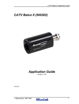
Operations and Controls
1. Gain:
Adjust potentiometer for overall amplifier gain level.
2. Tilt:
Adjust potentiometer provides for slope adjustment over entire bandwidth.
3. IN:
The input RF signal is connected to this port.
4. OUT:
The amplified RF signal is available at this port.
5. -20 dB Input Test Monitor:
Input test point is provided to monitor input level to the amplifier.
6. -20 dB Output Test Monitor:
Output test point is provided for amplifier set up and monitoring.
7. Power cable:
The three-prong type power plug connects to a 120 VAC, 60 Hz electrical outlet.
54-550MHz
30dB GAIN
GAIN TILT
POWER IN
-20dB
OUTPUT TEST
CA30/550
550MHz Push-Pull Distribution Amplifier
TRU SPEC
AC 117V
-20dB
INPUT TEST
MAX MAX
OUT
IN
Front Panel Controls and Specifications
CA30550 Manual.qxd 7/7/03 12:59 PM Page 6

CA30/550
Installation Procedure
7
Rev. 06/03
Ph:800-421-6511 www.picomacom.com
Installation
BASIC INSTALLATION
1. Mount unit securely by attaching screws or bolts through mounting tabs of unit and into an equipment rack, wall
or other solid structure.
2. Attach a cable from the RF input of CA-30/550 to the source RF signal.
3. Attach a cable from the RF output of CA-30/550 to the distribution system output.
4. Connect unit power cord to wall receptacle or power strip supplying line power.
5. Connect a RF spectrum analyzer or signal level meter to the input test point.
6. Use the loading chart listed under operating guidelines as a guide to ensure that the input level does not exceed
the suggested amplitude level for the number of channels. If needed, reduce the input level using attenuators (FAM
or PPFAM) for proper operation.
7. Connect a RF spectrum analyzer or signal level meter to the output test point.
8. Adjust the amplifier output level to match the distribution amplitude and tilt requirements.
Note:The setup procedure above and loading restrictions below assume that the RF source channels are all received
at the same amplitude level.
OPERATING GUIDELINES
Below is a chart showing the proper operation level for the CA30/550. Please note the listed performance criteria is
for SPECIFIC numbers of channels, and must be de-rated accordingly when inserting additional channels. Also note
the amplifier's gain does not change. However, as the number of channels increases from 7 channels, the input level
(hence, the output level) must be reduced. Exceeding the input levels listed below will cause intermodulation and pic-
ture distortions.
INPUT LEVELS
Total # of
Channels
Max. Input
Level
Max. Output Level
@ Max Slope
736 dBmV 65 dBmV
12 33 dBmV 57 dBmV
36 25 dBmV 50 dBmV
54 16 dBmV 46 dBmV
77 13 dBmV 44 dBmV
CA30550 Manual.qxd 7/7/03 1:00 PM Page 7

CA30/550
8
Rev. 06/03 Ph:800-421-6511 www.picomacom.com
Limited Warranty
Pico Macom warrants to the original purchaser that all of its new products are of sound design, quality materials and workmanship at the time of manufacture
and will be free from related defects for one year from the original purchase date. Pico Macom will repair or, at its discretion, replace without cost to the original
purchaser, the product which, upon inspection by Pico Macom, appears to be defective or not conforming to factory specifications. Pico Macom will cover the cost
of parts, labor, and return freight from factory.
Five-Year Limited Warranty
Most products designated as “Headend Electronics”are further covered by an extended 4-year period beyond the expiration of the original 1-year warranty, for a full
5-year period. Qualified equipment requiring factory repair during the extended 4-year period is covered under our re-certification program. Re-certification fees
under this program shall not to exceed 20% of the product’s List Price and whenever possible, Pico Macom will attempt to upgrade performance to the latest
improved specification.
Warranty Limitations
This warranty excludes coverage of damage or inoperability resulting from (1) use or installation other than in strict accordance with Pico Macom’s written instruc-
tions, (2) disassembly or repair by someone other than Pico Macom or a Pico Macom authorized repair center, (3) misuse, misapplication or abuse, (4) alteration,
(5) lack of reasonable care or (6) wind, ice, snow, rain, lightning, power surges, or any other weather conditions or acts of God. Pico Macom’s warranty with respect
to third-party proprietary sub-assembly modules and/or private-label products are limited to the duration and terms of third-party vendors’ warranty. Pico Macom
shall in no event and under no circumstances be liable or responsible for any consequential, indirect, incidental, punitive, direct or special damages based upon
breach of warranty, breach of contract, negligence, strict tort liability or otherwise or any other legal theory, arising directly or indirectly from the sale, use, installa-
tion or failure of any product acquired by buyer from Pico Macom.This limited warranty extends to the original purchaser. Pico Macom reserves the right to modify
or discontinue this warranty at Pico Macom’s sole discretion without notification. No other warrantees are expressed or implied.
Uptime Loaner Program
Our Uptime loaner program is designed to provide domestic users of our headend products and commercial systems the best possible support and service. This
program is established to minimize downtime resulting from equipment failure in critical service situations. We offer this program free-of-charge (excluding freight)
to qualified purchasers within the warranty period.The program provides a free equipment loan of like qualified equipment enabling seamless operation for the time
required to repair and return the unit.
The process is simple. Call our Customer Service desk requesting a return-merchandise-authorization (RMA) number for the failed equipment and ask for a loaner
unit. We will issue an invoice for the List Price of the loaner unit plus shipping costs.When you receive the loaner unit, pack the failed unit in the loaner unit’s box
and ship it freight prepaid to Pico Macom for repair. When you receive the repaired unit, a new RMA number will be provided in the box. Carefully pack the loaner
unit and affix the new RMA number on the box and ship it back to us for full credit excluding shipping costs.
To qualify for the program, you must have current open-terms with us and in good standing. We must receive your failed unit within one week after the loaner unit
is shipped to you, and must likewise receive the loaner unit within one week after the repaired unit is shipped back to you. Daily rental fees not to exceed 10% of
the equipment’s List Price will apply beyond one week after the loaner or repaired unit are shipped to you. Other limitations may apply, so please call us for addi-
tional information on qualifying equipment and procedures. Pico Macom reserves the right to modify or discontinue the Uptime Loaner Program at any time, and at
its sole discretion.
Damage or Shortage Claims
Our shipping staff carefully packs and ships your orders in compliance with common carriers’ requirements.Please make note of any obvious damage or shortage
on the freight bill or carrier’s receipt next to your signature. The carrier’s agent must too sign acknowledging the loss. Failure to do so may result in the carrier’s
refusal to honor the claim. Please open your order immediately upon receipt to check for concealed damage and compare the packing list to the items shipped. If
damaged, keep the original shipping cartons for possible inspection by the carrier.You must report claims for loss or damage within 3 days of delivery, while claims
for erroneous charges or price corrections must be presented within 30 days of invoice date.
Returning Shipped Items
To return any shipped items, including those shipped for warranty repairs or credit, call our Customer Service desk to request a Return Merchandise Authorization
(RMA) number. Please reference the original invoice number and purchase date, and product serial number (if any). Be certain to mark the RMA number on the
package boldly and legibly. Unless we specify a different carrier, please ship your returned items to us via UPS freight prepaid and fully insured. If returned for
credit, we will promptly process your request upon receipt of your return order.
Our Return Policy: Your Satisfaction Guaranteed
Our goal is your complete satisfaction. If for any reason, our products were not quite what you anticipated, simply call your customer service rep and
we will be happy to assist you in replacing or returning the order.You may return current, non-discontinued items for full credit for up to 30 days from
invoice date. Our requirements are simple: Excepting defective items, the products must be returned in their original packaging and in re-salable
condition. Restocking fees may otherwise apply beyond this period or if products are not returned in their original condition. Please contact your
customer service rep for more information.
Warranty
CA30550 Manual.qxd 7/7/03 1:00 PM Page 8
/