Motorola BLE100 User manual
- Category
- Chassis components
- Type
- User manual

Installation and
Operation Manual
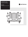
BLE100
1GHz Broadband Line Extender
B
M
L
E
E
S
S
D
A
I
N
O
C
M
I
X
E
4
2
6
3
1
5

Caution
These servicing instructions are for use by qualified personnel only. To reduce the risk of electrical shock, do not perform any servicing other than that
contained in the Installation and Troubleshooting Instructions unless you are qualified to do so. Refer all servicing to qualified service personnel.
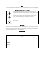
Special Symbols That Might Appear on the Equipment
This symbol indicates that dangerous voltage levels are present within the equipment. These voltages are not
insulated and may be of sufficient strength to cause serious bodily injury when touched. The symbol may also appear
on schematics.
The exclamation point, within an equilateral triangle, is intended to alert the user to the presence of important
installation, servicing, and operating instructions in the documents accompanying the equipment.
For continued protection against fire, replace all fuses only with fuses having the same electrical ratings marked at
the location of the fuse.
FCC Compliance
This equipment has been tested and found to comply with the limits for a Class A digital device, pursuant to Part 15 of the FCC Rules. These limits are
designed to provide reasonable protection against harmful interference when the equipment is operated in a commercial environment. This equipment
generates, uses, and can radiate radio frequency energy and, if not installed and used in accordance with the Installation Manual, may cause harmful
interference to radio communications. Operation of this equipment in a residential area is likely to cause harmful interference in which case the user
will be required to correct the interference at his/her own expense. Any changes or modifications not expressly approved by Motorola could void the
user’s authority to operate this equipment under the rules and regulations of the FCC.
Canadian Compliance
This Class A digital apparatus meets all requirements of the Canadian Interference-Causing Equipment Regulations.
Cet appareil numérique de la classe A respects toutes les exigences du Règlement sur le matériel brouilleur du Canada.
Declaration of Conformity
We Motorola, Inc.
101 Tournament Drive
Horsham, PA 19044, U.S.A.
declare under our sole responsibility that the
STARLINE
®
Model BLE100
to which this declaration relates is in conformity with one or more of the following standards:
EMC Standards
EN55022 EN55024 EN50083-2 CISPR-22 CISPR-24
Safety Standards
EN60065 EN60825 EN60950 IEC 60950 + A1: 1992 + A2: 1993 + A3: 1995 + A4: 1996
following the provisions of the Directive(s) of the Council of the European Union:
EMC Directive 89/336/EEC Low Voltage Directive 73/23/EEC

Copyright © 2006 by Motorola, Inc.
All rights reserved. No part of this publication may be reproduced in any form or by any means or used to make any derivative work (such as
translation, transformation or adaptation) without written permission from Motorola, Inc.
Motorola reserves the right to revise this publication and to make changes in content from time to time without obligation on the part of Motorola to
provide notification of such revision or change. Motorola provides this guide without warranty of any kind, either implied or expressed, including, but
not limited to, the implied warranties of merchantability and fitness for a particular purpose. Motorola may make improvements or changes in the
product(s) described in this manual at any time.
MOTOROLA, Intelligence Everywhere and the Stylized M Logo are registered in the US Patent & Trademark Office. All other product or service names
are the property of their respective owners. © Motorola, Inc. 2006

BLE100 Installation and Operation Manual
Contents
Section 1
Introduction
Using This Manual ...........................................................................................................................................................................1-3
Related Documentation...................................................................................................................................................................1-3
Document Conventions...................................................................................................................................................................1-3
If You Need Help...............................................................................................................................................................................1-4
Calling for Repairs...........................................................................................................................................................................1-5
Section 2
Overview
Ordering Matrix ................................................................................................................................................................................2-2
Housing.............................................................................................................................................................................................2-3
Gaskets.............................................................................................................................................................................................2-4
Port Locations..................................................................................................................................................................................2-5
Power Supply ...................................................................................................................................................................................2-6
Forward Path....................................................................................................................................................................................2-7
Return Path.......................................................................................................................................................................................2-7
Ingress Control Switch....................................................................................................................................................................2-8
Options and Accessories................................................................................................................................................................2-8
Section 3
Amplifier Setup
Proper Handling Procedures..........................................................................................................................................................3-1
Field Practice...........................................................................................................................................................................3-1
Bench Setup ............................................................................................................................................................................3-1
Forward Path Alignment..................................................................................................................................................................3-2
Before You Begin....................................................................................................................................................................3-2
STARLINE Cable Equalizers ..................................................................................................................................................3-3
Example 1........................................................................................................................................................................3-3
Example 2........................................................................................................................................................................3-3
STARLINE Cable Simulators..................................................................................................................................................3-6
Input and Midstage Pads........................................................................................................................................................3-7
Flatness Control......................................................................................................................................................................3-7
Directional Coupler Test Points.............................................................................................................................................3-8
Bode Equalization...................................................................................................................................................................3-8

ii Contents
BLE100 Installation and Operation Manual
Amplifier Level Control...........................................................................................................................................................3-9
Manual Gain Control.......................................................................................................................................................3-9
Automatic Drive Unit/QAM Automatic Drive Unit......................................................................................................3-11
ADU/QADU Pads and Levels .......................................................................................................................................3-12
Return Path Alignment...................................................................................................................................................................3-12
Before You Begin...................................................................................................................................................................3-12
Alignment Procedure ............................................................................................................................................................3-13
Powering and Surge Protection....................................................................................................................................................3-14
Section 4
Bench Testing
Before You Begin..............................................................................................................................................................................4-1
Test Equipment and Connections ..................................................................................................................................................4-2
Measuring Forward Gain.........................................................................................................................................................4-2
Example:..........................................................................................................................................................................4-3
Example:..........................................................................................................................................................................4-3
Testing Return Gain and Response.......................................................................................................................................4-4
Example:..........................................................................................................................................................................4-4
Completing the Test Procedures ...........................................................................................................................................4-4
Section 5
Installation
Aerial Installation..............................................................................................................................................................................5-1
Pedestal Installation.........................................................................................................................................................................5-3
Section 6
Operating Tips
Using Amplifiers in Lower Frequency Systems............................................................................................................................6-1
Using Amplifiers in Lower Gain Systems......................................................................................................................................6-1
Appendix A
Specifications
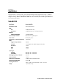
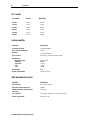
Model BLE100S................................................................................................................................................................................A-1
AC Current........................................................................................................................................................................................A-2
Return Amplifier...............................................................................................................................................................................A-2
ADU Automatic Drive Unit..............................................................................................................................................................A-2

Contents iii
BLE100 Installation and Operation Manual
Appendix B
Torque Specifications
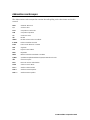
Abbreviations and Acronyms
Figures
Figure 1-1 BLE100 – closed...........................................................................................................................................................1-1
Figure 1-2 BLE100 – open..............................................................................................................................................................1-2
Figure 2-1 BLE100 base with electronics module.......................................................................................................................2-1
Figure 2-2 BLE100 ordering matrix...............................................................................................................................................2-2
Figure 2-3 BLE-HSG/15 housing and dimensions.......................................................................................................................2-3
Figure 2-4 Housing gaskets...........................................................................................................................................................2-4
Figure 2-5 Housing ports................................................................................................................................................................2-5
Figure 2-6 BLE100 power supply ..................................................................................................................................................2-6
Figure 2-7 BLE100 block diagram.................................................................................................................................................2-7
Figure 2-8 BLE100 options and accessories..............................................................................................................................2-10
Figure 3-1 Equalizer slope versus cable.......................................................................................................................................3-5
Figure 3-2 Frequency versus cable slope ....................................................................................................................................3-7
Figure 3-3 LDR/9/1G component layout (top-left, bottom-right) ................................................................................................3-8
Figure 3-4 ADU..............................................................................................................................................................................3-11
Figure 3-5 QADU ...........................................................................................................................................................................3-11
Figure 4-1 Test equipment connections for bench sweeping....................................................................................................4-2
Figure 5-1 Center-conductor pin length .......................................................................................................................................5-1
Figure 5-2 Torque sequence..........................................................................................................................................................5-2
Tables
Table 2-1 BLE100 options and accessories.................................................................................................................................2-8
Table 3-1 Starline Forward Equalizers – SFE-100-*.....................................................................................................................3-4
Table 3-2 STARLINE Cable Simulators.........................................................................................................................................3-6
Table 3-3 Gain reserve versus ambient temperature..................................................................................................................3-9

BLE100 Installation and Operation Manual
Section 1
Introduction
The Motorola 1 GHz STARLINE
®
series of broadband line extenders, BLE100, accept a single
input and provide 34 dB of operational gain to a single output. The BLE100 series of line
extenders meets Telcordia GR-1098 core voltage surge requirements using surge waveforms as
described in IEEE C62.41. The BLE100 is also FCC, CE, and CCC approved.
Features of the BLE100 include:
1003 MHz power doubling technology in enhanced gallium arsenide (E-GaAs)
Four different modular diplex filter frequency split options
Ergonomics
60/90 VAC line power option
Thermal and auto-controlled Bode equalization
−20 dB directional coupler test points
Optional return path ingress control accessories
Two-way operation capability
15-amp power passing
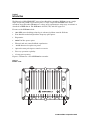
Figure 1-1 illustrates a closed BLE100 line extender.
Figure 1-1
BLE100 – closed
A
S
S
E
M
B
L
E
D
I
N
M
E
X
I
C
O
4
2
6
3
1
5

1-2 Introduction
BLE100 Installation and Operation Manual
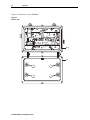
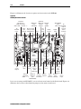
Figure 1-2 illustrates an open BLE100.
Figure 1-2
BLE100 – open
Base
Lid
SRE-X-XX
SFE-100-XX
L
IN
JXP
-20dB
ICS
JXP OUT
EQ
RTN
THERM
JXP
L
-20dB
FUSE VALUES
MANUAL FOR
REFER TO
DISCHARGE (ESD)
DAMAGE BY ELECTROSTATIC
ASSEMBLIES SUSCEPTIBLE TO
CAUTION: CONTAINS PARTS AND
-16dB
MONITOR
STATUS
H
OUT
REFER TO MANUAL
CHECK VOLTAGE
SELECTOR
-20dB
JXP
ADU
ADU
N
J
K
A
S100
87
ADU
BODE
ASSEMBLED IN MEXICO
TEST
MONITOR
STATUS
FUSE
RCB100
BLE
H
POINT
FUSE
TDU
AUTO
ALIGN DOTS
JXP IN
IN
-20dB
EQ
FWD
MAN
JXP MID
LDR
AC
RC
+24V DC
TEST POINT
MAN

Introduction 1-3
BLE100 Installation and Operation Manual
Using This Manual
The following sections provide information and instructions to bench test, install, and operate
the BLE100.
Section 1 Introduction provides a brief description of the product, identifies the information
contained in this manual, and gives the help line telephone number and repair return
information.
Section 2 Overview describes the BLE100 and includes details on the various options and their
functions.
Section 3 Amplifier Setup provides instructions for full configuration and forward- and return-path
alignment.
Section 4 Bench Testing describes the bench test procedures that are recommended before
installing the BLE100.
Section 5 Installation provides instructions for installing the BLE100 and performing field alignment.
Section 6 Operating Tips provides suggestions for handling field-encountered variables and
addressing maintenance tasks.
Appendix A Specifications lists the applicable technical specifications for the BLE100 and options.
Appendix B Torque Specifications provides the appropriate torque specifications for the screws,
clamps, connectors, and bolts used in the BLE100.
Abbreviations
and Acronyms
The Abbreviations and Acronyms list contains the full spelling of the short forms used in
this manual.
This installation manual assumes that all channels are standard National Television Standards
Committee (NTSC) analog channels. Refer to catalog specifications for further details pertaining
to signal levels of digital channels above 550 MHz.
This installation manual uses 1003 MHz as the reference frequency unless another frequency is
given. For example, quoted cable loss is understood to be at 1003 MHz.
Related Documentation
This installation manual is complete and you should not require any additional documentation
to install, test, or operate the BLE100 line extender.
Document Conventions
Before you begin to use the BLE100, familiarize yourself with the stylistic conventions used in
this manual:
Bold type
Indicates text that you must type exactly as it appears or indicates a default value
SMALL CAPS
Denotes silk screening on the equipment, typically representing front and rear-panel
controls, I/O connections and indicators (LEDs).
* (Asterisk)
Indicates that there are several versions of the same model number and the information
applies to all models. When the information applies to a specific model, the complete model
number is given.
Italic type
Denotes a displayed variable, a variable that you must type, or is used for emphasis

1-4 Introduction
BLE100 Installation and Operation Manual
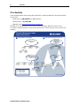
If You Need Help
If you need assistance while working with the BLE100, contact the Motorola Technical Response
Center (TRC):
Inside the U.S.: 888-944-HELP (1-888-944-4357)
Outside the U.S.: 215-323-0044
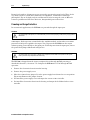
Motorola Online:
http://businessonline.motorola.com
The TRC is on call 24 hours a day, 7 days a week. In addition, Motorola Online offers a
searchable solutions database, technical documentation, and low-priority issue creation and
tracking.
http://businessonline.motorola.com
Data Networks/
Transmission Products
PRESS 3
Products
PRESS 1
Cable Router
VOIP
PRESS 2
Cable Modems
Products
PRESS 3
Transmission
Transport
Products
(MBT/MWT/MEA)
PRESS 5
Multiservice
Management
PRESS 4
Network
Licensing
PRESS 1
Network
Management
Products
PRESS 2
Network
Technical Response Center
Telephone Menu Options
Connected Home Solutions
Video Products
PRESS 1
Issued: 04/2005
Broadcaster,
Satellite IRD or
Encoder Products
PRESS 2
Severity Level
1 - Critical Failure
2 - Serious Failure
3 - Lesser Failure
4 - Technical Assistance
PRESS 3
Set-tops
PRESS 2
Headend
PRESS 1
Controllers
PRESS 2
Analog
PRESS 1
Digital
IRD
PRESS 1
Commercial
Encoder
PRESS 2
Uplink
888-944-HELP / 215-323-0044
Consumer
Products
PRESS 4
Satellite
C Band
PRESS 1
Consumer
Retail
Support
PRESS 2
Broadband

Introduction 1-5
BLE100 Installation and Operation Manual
Calling for Repairs
If repair is necessary, call the Motorola Repair Facility at 1-800-227-0450 for a Return for
Service Authorization (RSA) number before sending the unit. The RSA number must be
prominently displayed on all equipment cartons. The Repair Facility is open from 8:00 AM to
5:00 PM Central Time, Monday through Friday.
When calling from outside the United States, use the appropriate international access code and
then call 956-541-0600 to contact the Repair Facility.
When shipping equipment for repair, follow these steps:
1 Pack the unit securely.
2 Enclose a note describing the exact problem.
3 Enclose a copy of the invoice that verifies the warranty status.
4 Ship the unit PREPAID to the following address:
BCS Nogales Repair Center
Attn: RSA #_________
6908 East Century Park Drive
Tucson, AZ 85706
US

BLE100 Installation and Operation Manual
Section 2
Overview
The BLE100 is a two-way capable line extender used in CATV distribution systems. The
BLE100 is powered by the 60/90 VAC cable supply and can be configured to pass this power to
additional line extenders. Installation of the return path enables two-way signal flow.
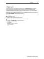
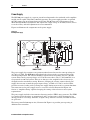
The standard model BLE100 includes an amplifier module with an integrated DC power supply,
which is normally furnished complete in the model BLE-HSG/15 housing, as shown in
Figure 2-1.
Figure 2-1
BLE100 base with electronics module
SRE-X-XX
SFE-100-XX
L
IN
JXP
-20dB
ICS
JXP OUT
EQ
RTN
THERM
JXP
L
-20dB
FUSE VALUES
MANUAL FOR
REFER TO
DISCHARGE (ESD)
DAMAGE BY ELECTROSTATIC
ASSEMBLIES SUSCEPTIBLE TO
CAUTION: CONTAINS PARTS AND
-16dB
MONITOR
STATUS
H
OUT
REFER TO MANUAL
CHECK VOLTAGE
SELECTOR
-20dB
JXP
ADU
ADU
N
J
K
A
S100
87
ADU
BODE
ASSEMBLED IN MEXICO
TEST
MONITOR
STATUS
FUSE
RCB100
BLE
H
POINT
FUSE
TDU
AUTO
ALIGN DOTS
JXP IN
IN
-20dB
EQ
FWD
MAN
JXP MID
LDR
AC
RC
+24V DC
TEST POINT
MAN

2-2 Overview
BLE100 Installation and Operation Manual
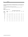
Ordering Matrix
Several models of the BLE100 are available. The BLE100 is fully configured in the Motorola
factory per customer request. You can find the model name on labels on the outside of the
shipping carton, the side of the BLE100 housing, and the side of the electronics module.
Please see the Product Data Sheet on the Motorola on line Product Catalog for available models
and associated part numbers.
Figure 2-2 identifies and describes the model strings.
Figure 2-2
BLE100 ordering matrix
BLE
Key
X
Station Slope
9 dB (Fmin-1003 MHz)
Key
X
Return Gain
High (24 dB)
Key
100S
100K
100A
100J
100N
Bandpass Split
5-40 MHz/52-1003 MHz
5-42 MHz/54-1003 MHz
5-65 MHz/85-1003 MHz
5-55 MHz/70-1003 MHz
5-85 MHz/105-1003 MHz
Key
H
Gain
E-GaAs (High Output w/34 dB Gain)
* Electronics modules available are configured for manual level control only.
The ADU must be ordered and installed separately.
Notes:
1. FTECs and 20A fuses are included in all amplifiers as standard.
2. ICS and status monitor transponders will continue to be customer configurable options.
Housing*
E15
F
E10
Electronics only (15 amp)
Electronics only (10 amp)
Standard (Full Station)
Key
Key
X
A
Q
Level Control
None
ADU-499.25/S
QADU-609.00/S

Overview 2-3
BLE100 Installation and Operation Manual
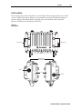
Housing
The BLE100 is furnished in a BLE-HSG/15 aluminum housing that protects the electronics
from weather and dissipates internally generated heat.
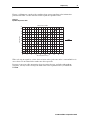
Figure 2-3 illustrates the BLE-HSG/15 housing and provides its dimensions.
Figure 2-3
BLE-HSG/15 housing and dimensions
10.6
8.0
4.7
A
S
S
E
M
B
L
E
D
I
N
M
E
X
I
C
O
4
2
6
3
1
5
Coaxial cable connections to the housing are made using conventional 5/8 inch × 24 threads
per-inch stinger-type connectors. Four port plugs in the cover enable access to internal test
points without opening the housing.
The BLE-HSG/15 differs from the housing of the 10A BLE (model BLE-75SH and BLE-75JH)
and the JLX series of line extenders. However, you can upgrade the 10A BLE and the JLX
series of line extenders to the 15A BLE100 using the existing housing. To upgrade from 10A to
15A, use the BLE-15A platform assembly kit (P/N 951941-006-00). The BLE-15A kit contains
15A platform assemblies. As an alternative to the kit, you can order the BLE100 electronics
module configured as a 10A unit (see Fig.2-2 BLE100 ordering matrix, Housing).
Two messenger clamps are located on the side of the housing (Figure 2-5) and are secured with
5/16 inch × 24 threads-per-inch stainless steel bolts. The bottom of the housing also contains two
5/16 × 24 threaded holes located on the vertical center-line separated by four inches
center-to-center. Use these holes and the bolts from the messenger clamps for pedestal and
surface-mounting installations.

2-4 Overview
BLE100 Installation and Operation Manual
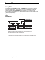
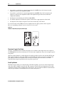
Gaskets
Each housing is equipped with a recessed woven-wire RF gasket and a silicone-rubber gasket to
provide a seal between the housing base and lid. These gaskets provide efficient ground
continuity, RF shielding, and weather protection. Both gaskets must be in place and in good
condition to ensure proper operation and protection of the station. The weather gasket should be
lightly coated with silicone grease each time the BLE100 is opened. Replace this gasket if it
becomes damaged or deformed.
Figure 2-4
Housing gaskets
SRE-X-XXSRE-X-XX
SFE-100-XX
L
IN
JXP
-20dB
ICS
JXP OUT
EQ
RTN
THERM
JXP
L
-20dB
FUSE VALUES
MANUAL FOR
REFER TO
DISCHARGE (ESD)
DAMAGE BY ELECTROSTATIC
ASSEMBLIES SUSCEPTIBLE TO
CAUTION: CONTAINS PARTS AND
-16dB
MONITOR
STATUS
H
OUT
REFER TO MANUAL
CHECK VOLTAGE
SELECTOR
-20dB
JXP
ADU
ADU
N
J
K
A
S100
87
ADU
BODE
ASSEMBLED IN MEXICO
TEST
MONITOR
STATUS
FUSE
RCB100
BLE
H
POINT
FUSE
TDU
AUTO
ALIGN DOTS
JXP IN
IN
-20dB
EQ
FWD
MAN
JXP MID
LDR
AC
RC
+24V DC
TEST POINT
MAN
Weather gasket
(silicone rubber)
RF gasket
(woven wire)

Overview 2-5
BLE100 Installation and Operation Manual
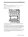
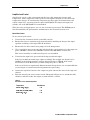
Port Locations
Two housing ports provide connection for coaxial cables. Four port plugs in the cover enable
access to internal test points. All ports are protected by factory-inserted threaded plugs or
plastic cap plugs. Discard the plastic cap plugs when you install the cable connectors.
Figure 2-5 illustrates the housing port locations.
Figure 2-5
Housing ports
A
S
S
E
M
B
L
E
D
I
N
M
E
X
I
C
O
4
2
6
3
1
5
Port 1
Port 2
Lid
Messenger
clamp bolts
Test ports Test ports

2-6 Overview
BLE100 Installation and Operation Manual
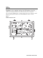
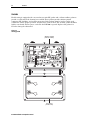
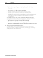
Power Supply
The BLE100 power supply is a separate circuit board mounted to the underside of the amplifier
module and is capable of 60 VAC or 90 VAC powering. The power supply provides a regulated
24 VDC output over an AC input between 38 Vrms and 90 Vrms with a line frequency from
50 Hz through 60 Hz. Potentiometer R25 adjusts the output voltage to 24 VDC, however, this is
set at the factory and field adjustment is not recommended.
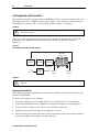
Figure 2-6 illustrates the components on the power supply.
Figure 2-6
BLE100 power supply
The power supply also contains a two-position
LO/HI selector that sets the start-up voltage for
38 VAC or 55 VAC. The BLE100 is shipped with the selector in the
LO position which is the
standard configuration. The selector should be switched to the
HI position only for a 90 VAC
system. This sets the start-up voltage at 55 VAC. Because this is only 5 V below 60 VAC, it is
not practical in a 60 VAC system. There is no damage to the amplifier if the selector is not
changed from the standard
LO setting. However, changing the selector ensures that the DC
supply does not turn on until the proper input voltage, 38 VAC or 55 VAC, is reached. This
prevents excessive loading of the system power supply during turn-on after a system shutdown.
You must remove the power supply cover to access the selector illustrated in Figure 2-6.
Section 3, “Amplifier Setup” explains changing the setting of this selector to meet system
requirements.
The power supply includes a fast-transfer electronic-crowbar (FTEC) surge protector. The FTEC
is a crowbar circuit that fires at approximately 245 V and presents a short circuit to the line
during periods of overvoltage. After the ac input voltage returns to normal, the FTEC resumes
its open state.
The factory-installed 20-ampere fuse, illustrated in Figure 2-8, provides power-passing to
additional line extenders.

Overview 2-7
BLE100 Installation and Operation Manual
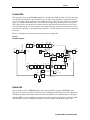
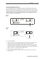
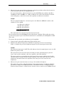
Forward Path
The operational gain of the BLE100 amplifiers is 34 dB with 16 dB of return loss. The operating
gain includes provisions for the insertion loss of the input cable equalizer and required reserve
gain to operate the Bode equalizer in the middle of its range. The low-noise figure, pre-amplifier
stage, is a 1 GHz hybrid followed by a power-doubled output stage. Between the two stages is a
JXP-*B pad socket, the Bode board, and the flatness and equalizer board. Because these losses
are located interstage, the noise figure is only significantly impacted by the insertion loss of the
forward cable equalizer or broadband cable simulator, and the input pad if its value is increased
from zero.
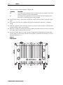
Figure 2-7 illustrates the interconnection among these components:
Figure 2-7
BLE100 block diagram
24 Vdc
DC test point
Power
supply
Input
port
JXP-B
-16 dB
JXP-B
LPF
BODE
RC
Therm
PP
PD
TP
-20 dB
AC test
point
JXP-B
Manual
LDR
H
L
-20 dB
TP
Auto
ICS
JXP
TP
-20 dB
Power
Block
Jumper
** Plug-in module
FTEC
Status
monitor
Surge
protector
Surge
protector
SFE
or
SCS
JXP-B
-
-1.0 dB
-1.0 dB
-1.0 dB
28 dB -6.5 dB-1.0 dB
-1.0 dB
-1.0 dB
SRE
-0.5 dB
+30.0 dB -0.3 dB
-0.4 dB
-0.4 dB
-0.4 dB
RF
RF/
AC
AC
-1.7
dB F
-1.0
dB R
23 dB
TP
Return
injection point
-20 dB
OnBrd
Atten
~-3dB
Output
port
H
L
RF/
AC
AC
RF
-1.7
dB F
-1.0
dB R
JXP-B
OnBrd
Atten
ADU/
TDU
Fuse
Return Path
The circuit board of the BLE100 includes the return path. This equips the BLE100 to pass
signals in the return or upstream direction. The standard circuit board contains all components
including the diplex filters with extended return bandwidth for the amplifier input and output.
Optional SRE-*-* return equalizers compensate for cable attenuation and are available in 1 dB
increments for S-split, and 2 dB increments for all other splits, from 0 dB through 12 dB.

2-8 Overview
BLE100 Installation and Operation Manual
The input and output of the return path each include a JXP-*B pad facility. You can also use
either pad socket as a test point or a signal injection point. The return output pad value is
normally selected to control the return signal level into the next upstream amplifier. Select an
appropriate return input pad to attenuate excessive input signal.
The return-input test point and the return-output test point are −20 dB directional couplers.
Both test points present 75-ohm source impedance and do not require special test probes.
Ingress Control Switch
The ingress control switch (ICS) provides return-path signal attenuation or cutoff in the
BLE100. This is accomplished through the frequency agile LIFELINE
®
status-monitoring
module, which you can purchase directly from AM Networks. (Figure 2-8 illustrates the location
of the optional ICS).
The ICS provides a means of isolating sources of ingress from a centralized location. Using a
downstream command through the LIFELINE status-monitoring system, you can attenuate the
return path through the line extender by 6 dB or by 38 dB. By reducing the ingress level at the
headend or monitoring point, you can further isolate the ingress source.
After an ingress source is isolated to the last possible amplifier, node, or line extender, you can
shut the return path off at that location. This limits the impact of the ingress on the remainder
of the network while eliminating the source of ingress.
Options and Accessories
The factory ships the BLE100 as a fully functional unit, but you must configure it appropriately
for the field-location requirements. You must install the correct forward equalizer or broadband
cable simulator and input pad to place the unit into service. Section 3, “Amplifier Setup”
provides information to assist you in this task. Use model JXP-*B pads to control field signal
levels. To compensate for temperature, install the automatic drive unit (ADU) or QAM
automatic drive unit (QADU) before placing the BLE100 in service. You can install other items,
such as return thermal attenuators or ingress control switches at your discretion, but these
options do not render the BLE100 inoperative if they are not included.
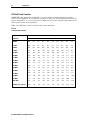
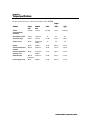
Table 2-1 provides a comprehensive list of options and accessories for the BLE100. See
Section 3, “Amplifier Setup,” or the Motorola online product catalog for additional information.
Table 2-1
BLE100 options and accessories
Model Description Function
QADU-*
QAM Automatic Drive Unit This board automatically controls amplifier output levels
that change with cable attenuation and hybrid output.
The selection of an appropriate pilot frequency is
required.
ADU-*
Automatic Drive Unit This board automatically controls amplifier output levels
that change with cable attenuation and hybrid output.
The selection of an appropriate pilot frequency is
required.

Overview 2-9
BLE100 Installation and Operation Manual
Model Description Function
SFE-100-*
Starline Forward Equalizer This 1 GHz equalizer compensates for cable properties
in 1 dB increments from 0 dB through 22 dB. The
appropriate value must be installed.
SRE-*-*
Starline Return Equalizer This bandwidth specific equalizer compensates for
cable attenuation in 1 dB increments from 0 dB through
12 dB for S-split (2 dB increments for all other splits).
The appropriate value must be installed.
SCS-*
Starline Cable Simulator This simulator compensates for cable properties. The
appropriate value must be installed.
JXP-*B
Fixed attenuator This pad attenuates excessive input signal and can be
used to adjust amplifier gain. It is available in 1 dB
increments from 0 dB through 26 dB. The appropriate
value must be installed.
JXP-TH*C
Thermal attenuators This option compensates for gain changes with
temperature in the return path.
FTEC
Fast Transfer Electronic
Crowbar
This accessory is used for overvoltage protection.
BLE-LID/SM
Deep housing cover This optional cover is required to contain the LIFELINE
status monitor module which is available from AM
Networks.
BLE-RCB100
Response Correction Board This optional board compensates for system roll-off at
1 GHz. The BLE100 is shipped with a jumper in this
location which you can replace when additional
response correction is required.
JXP-RPC
Return Path Correction board This optional board provides additional flatness
response correction in the return path for systems that
must meet especially stringent return path flatness
requirements.
ICS-II
Ingress Control Switch This option enables remote monitoring, isolation, and
reduction of ingress on the return path by providing
signal attenuation of 6 dB or cutoff of 38 dB typical. The
unit is shipped with a jumper in this location. The
LIFELINE status monitoring module (available from AM
Networks) must be installed to control the ICS.
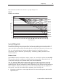
Figure 2-8 illustrates the location of options and accessories in the BLE100.
Page is loading ...
Page is loading ...
Page is loading ...
Page is loading ...
Page is loading ...
Page is loading ...
Page is loading ...
Page is loading ...
Page is loading ...
Page is loading ...
Page is loading ...
Page is loading ...
Page is loading ...
Page is loading ...
Page is loading ...
Page is loading ...
Page is loading ...
Page is loading ...
Page is loading ...
Page is loading ...
Page is loading ...
Page is loading ...
Page is loading ...
Page is loading ...
Page is loading ...
Page is loading ...
Page is loading ...
Page is loading ...
-
 1
1
-
 2
2
-
 3
3
-
 4
4
-
 5
5
-
 6
6
-
 7
7
-
 8
8
-
 9
9
-
 10
10
-
 11
11
-
 12
12
-
 13
13
-
 14
14
-
 15
15
-
 16
16
-
 17
17
-
 18
18
-
 19
19
-
 20
20
-
 21
21
-
 22
22
-
 23
23
-
 24
24
-
 25
25
-
 26
26
-
 27
27
-
 28
28
-
 29
29
-
 30
30
-
 31
31
-
 32
32
-
 33
33
-
 34
34
-
 35
35
-
 36
36
-
 37
37
-
 38
38
-
 39
39
-
 40
40
-
 41
41
-
 42
42
-
 43
43
-
 44
44
-
 45
45
-
 46
46
-
 47
47
-
 48
48


Motorola BLE100 User manual
- Category
- Chassis components
- Type
- User manual
Ask a question and I''ll find the answer in the document
Finding information in a document is now easier with AI
Related papers
-
Motorola RF Amplifier Quick start guide
-
Motorola BLE Series Operating instructions
-
-
-
-
-
-
-
Motorola SG 2000 Operating instructions
-
Other documents
-
Araknis Networks AN-700-AP-O-AC User guide
-
DRAKE DA7543 Installation guide
-
Maxview PSB Operating instructions
-
-
 Xtant RM-4 Owner's manual
-
Starline R7 Installation guide
-
-
-
Terra HA235R65 Owner's manual
-
Cumberland 8-01 Owner's manual
