Potter LFH Series User manual

Type
User manual

This manual is also suitable for

LFH-24 SERIES
LFHS-24 SERIES
ANSI/UL & CAN/ULC COMPLIANT
LOW FREQUENCY VISIBLE AND/OR AUDIBLE SIGNALING APPLIANCE
I. INTRODUCTION
The Potter Electric models LFH-24 and LFHS-24 are high quality low frequency audible and/or visible signaling appliances. This appliance is intended to provide a low frequency audible or
audible/visible, depending on the model, notification signal for the purpose of life safety and property protection. The LFHS-24 is a fixed candela unit; the candela intensities which can be
ordered are 15 Cd, 110Cd and 177Cd. The LFHS-24 strobe is listed in compliance with ANSI/UL 1971, Signaling Appliances for the Hearing Impaired.
This appliance is ideal for any occupancy that requires notification appliances per the applicable building or fire code or wherever dependable alarms are required. As of January 1, 2014
NFPA 72 requires that audible appliances installed in sleeping areas produce a low frequency alarm signal. For your information, the National Fire Protection Association's (NFPA) Standard 72,
2013 Edition, Chapter 18, Section 18.4.5 Sleeping Area Requirements, states the following:
18.4.5.3 Effective January 1, 2014, audible appliances provided for the sleeping areas to awaken occupants shall produce a low frequency alarm signal that complies with the following:
1) The alarm signal shall be a square wave or provide equivalent awakening ability
2) The wave shall have a fundamental frequency of 520Hz ± 10 percent
II. LOCATION
This appliance is intended for use in fire alarm systems and is to be installed in accordance with this manual, the recommendation of the local authorities having jurisdiction, and other NFPA
documents that provide standards on notification appliances for protective signaling systems. The LFH-24 and LFHS-24 are intended for indoor installations only; these appliances are not
listed for outdooror drip proof applications.
Wall mounted strobe appliances shall have their entire lens at heights above the finished floor of not less than 80 in. (2m) and not greater than 96 in. (2.4m)**. Spacing shall be in accordance
with Table A. If a room configuration is not square, the room size that will entirely encompass the room or subdivide the room into multiple squares shall be used. Wall mounted horn only
appliances shall have their tops above the finished floors at heights of not less than 90 in. (2.30m) and below the finished ceilings at heights of not less than 6 in. (152mm). Different mounting
heights shall be permitted by the AHJ provided the sound pressure level requirements of NFPA 72 are met.
III. MOUNTING, ROUGH-IN BOX AND RUN WIRING
This unit is designed for mounting to most single gang boxes, 4" square outlet boxes, 2-gang masonry boxes or non-metallic 2-gang switch boxes. Conduit entrance to boxes should be
selected to insure sufficient wiring clearance.
1. Run a minimum 18 gauge insulated 2 or more conductor cable.
2. Mount a box for each remote signaling appliance. Screw bracket onto box. Insert signal into bracket and slide to the right firmly into the terminal block receptacle. Insert mounting screw as
shown and tighten. Cover assembly with the plastic housing.
NOTICE:WIRING SHOULD BE CONNECTED TO MOUNTING BRACKET PRIOR TO MOUNTING SIGNAL. INCOMING POSITIVE POWER LEAD MUST BE BROKEN AND EACH LEAD IS
TO BE INSERTED INTO EACH OF THE TOP TWO TERMINALS. A BARRIER IS PROVIDED TO PREVENT BOTH LEADS FROM BEING PLACED UNDER THE SAME TERMINAL.
IV. AUDIBLE SIGNALING APPLIANCE OUTPUT
The three pulse temporal pattern (temporal 3) is to be used for evacuation use only.
The standard fire alarm evacuation signal is a three-pulse temporal pattern. The pattern consists of the following in this order:
(1) An “on” phase lasting 0.5 second ± 10 percent
(2) An “off” phase lasting 0.5 second ± 10 percent for three successive “on” periods
(3) An “off” phase lasting 1.5 seconds ± 10 percent
Total cycle lasts for 4 seconds ± 10 percent
The sound output for the temporal 3 tone is rated lower since the time the horn is off is averaged into the sound output rating. Units have been tested to C, 49°C and 93% humidity.
The four pulse temporal pattern (temporal 4) is to be used for carbon monoxide alarm signal use only.
The standard carbon monoxide alarm is a four pulse temporal pattern. The audible carbon monoxide alarm signal shall comply with the following:
(1) Signals shall be a single tone pattern consisting of four cycles of 100 milliseconds ± 10 percent “on” and 100 milliseconds of ± 10 percent “off,” followed by 5 seconds ±
10 percent “off.”
(2) After the initial 4 minutes of alarm, the 5-second “off” time shall be permitted to be changed to 60 seconds ± 10 percent.
The four pulse temporal pattern (Temporal 4) can only be obtained on this product when used in conjunction with the Potter Electric GTSM synchronization module or GTSM synchronization
protocol.
550-0649
Page 1
ADDITIONAL CAN/ULC LISTED PRODUCT INFORMATION IS FOUND ON PAGE 4
Horn Decibel Levels:
Reverberant Room
24VDC Nominal Horn
Current Ratings (mA)
Horn Current Ratings (UL Max)2
Over Input Voltage Range of 16-33V (mA)
Horn Mode
Minimum SPL
at 10Ft. Per
ANSI/UL 464
(NORMAL)
Minimum SPL
at 10Ft. Per
ANSI/UL 464
(LOUD)
24VDC
Operating
Current
(NORMAL)
24VDC
Operating
Current
(LOUD)
24VFWR
Operating
Current
(NORMAL)
24VFWR
Operating
Current
(LOUD)
Regulated
24VDC Max.
Operating
Current
(NORMAL)
Regulated
24VDC Max.
Operating
Current
(LOUD)
Regulated
24VFWR Max.
Operating
Current
(NORMAL)
Regulated
24VFWR Max.
Operating
Current
(LOUD)
Temporal 3 520 Hz 77.8 dBA 79.8 dBA 72.1 mA 120.1 mA 104.6 mA 158.4 mA 99.4 mA 155.8 mA 152.1 mA 213.5 mA
Temporal 4 520 Hz181.5 dBA 83.4 dBA 75.9 mA 116.0 mA 108.1 mA 182.0 mA 100.1 mA 157.2 mA 163.1 mA 235.2 mA
LFH-24 PRODUCT INFORMATION
1Temporal 4 520 Hz measured per ANSI/UL 2075
2 Recommended
LFH-24 Horn Decibel Levels and Current Ratings
550-0649
Page 2
V. WIRING
Wiring for synchronized strobes and horns.
Using this method you may:
Use the Potter Electric GTSM synchronization protocol to provide synchronization of temporal 3 and temporal 4 tones and mute the horn, if required.
NOTICE:
THIS APPLIANCE IS NOT RECOMMENDED FOR USE ON CODED OR PULSING SIGNALING CIRCUITS. HOWEVER, USE OF THE GTSM CONTROL MODULE IS PERMITTED TO
SYNCHRONIZE THE HORN.
THE FOUR PULSE TEMPORAL PATTERN (TEMPORAL 4) CAN ONLY BE OBTAINED ON THIS PRODUCT WHEN USED IN CONJUNCTION WITH THE POTTER ELECTRIC GTSM
SYNCHRONIZATION MODULE OR GTSM SYNCHRONIZATION PROTOCOL.
SEE GTSM CONTROL MODULE MANUAL (550-0634, MANUAL ISSUE DATE (02-01-15) FOR SYNCHRONIZATION MODULE WIRING DIAGRAMS. GTSM MANUAL CAN BE
OBTAINED BY CALLING POTTER ELECTRIC SIGNAL COMPANY AT 1-800-325-3936.
Conventional Method:
You may connect the horn directly from a source of rated power without the use of a control module. However, the horns will NOT be synchronized.
CAUTION: For the LFH-24 and LFHS-24, only the S+ and S- terminals are to be used
for connection to FACP. The H+ and H- terminals are to be used for dBA selection
using provided jumper. DO NOT APPLY VOLTAGE TO H+ AND H- TERMINALS.
Horn Decibel Levels:
Reverberant Room
Horn Mode
Minimum SPL
at 10Ft. Per ANSI/UL
464 (NORMAL)
Minimum SPL
at 10Ft. Per ANSI/UL
464 (LOUD)
Temporal 3 520 Hz 76.3 dBA 78.8 dBA
Temporal 4 520 Hz180.6 dBA 82.0 dBA
LFHS-24 PRODUCT INFORMATION
1Temporal 4 520 Hz measured per ANSI/UL 2075
2 Recommended
LFHS-24 Horn Decibel Levels and Horn/Strobe Current Ratings
Table A Room Spacing for Wall-Mounted Visible Appliances per NFPA 72, 2016 Edition
Maximum Room Size Minimum Required Light Output ( Effective Intensity, Cd)
Meters Feet One Light
per Room
Four Lights per Room
(One Light per Wall)
6.10 x 6.10 20 x 20 15 NA
8.53 x 8.53 28 x 28 30 NA
9.14 x 9.14 30 x 30 34 NA
12.2 x 12.2 40 x 40 60 15
13.7 x 13.7 45 x 45 75 19
15.2 x 15.2 50 x 50 94 30
16.5 x 16.5 54 x 54 110 30
16.8 x 16.8 55 x 55 115 30
18.3 x 18.3 60 x 60 135 30
19.2 x 19.2 63 x 63 150 37
20.7 x 20.7 68 x 68 177 43
21.3 x 21.3 70 x 70 184 60
24.4 x 24.4 80 x 80 240 60
27.4 x 27.4 90 x 90 304 95
30.5 x 30.5 100 x 100 375 95
33.5 x 33.5 110 x 110 455 135
36.6 x 36.6 120 x 120 540 135
39.6 x 39.6 130 x 130 635 185
**Effective Intensity Requirements for Sleeping Areas
Visible Notification Appliance
Distance from Ceiling to Top of Lens Intensity
greater than or equal to 24" 110cd
less than 24" 177cd
CAUTION:
Strobe light must be
installed within 16 feet
of the pillow when
used in a sleeping
area.
24VDC Nominal Horn/Strobe
Current Ratings (mA)
Horn/Strobe Current Ratings (UL Max)2
Over Input Voltage Range of 16-33V (mA)
Candela Horn Mode
24VDC
Operating
Current
(NORMAL)
24VDC
Operating
Current
(LOUD)
24VFWR
Operating
Current
(NORMAL)
24VFWR
Operating
Current
(LOUD)
Regulated 24VDC
Max. Operating
Current
(NORMAL)
Regulated 24VDC
Max. Operating
Current
(LOUD)
Regulated
24VFWR Max.
Operating
Current (NORMAL)
Regulated
24VFWR Max.
Operating
Current (LOUD)
15 Temporal 3 520 Hz 112.0 mA 144.0 mA 163.0 mA 198.0 mA 124.0 mA 182.0 mA 201.0 mA 252.0 mA
Temporal 4 520 Hz 158.0 mA 175.0 mA 210.0 mA 269.0 mA 195.0 mA 291.0 mA 273.0 mA 339.0 mA
110 Temporal 3 520 Hz 193.0 mA 223.0 mA 259.0 mA 295.0 mA 280.0 mA 326.0 mA 348.0 mA 427.0 mA
Temporal 4 520 Hz 241.0 mA 291.0 mA 325.0 mA 383.0 mA 384.0 mA 474.0 mA 470.0 mA 555.0 mA
177 Temporal 3 520 Hz 268.0 mA 293.0 mA 325.0 mA 329.0 mA 365.0 mA 393.0 mA 465.0 mA 478.0 mA
Temporal 4 520 Hz 337.0 mA 391.0 mA 428.0 mA 477.0 mA 427.0 mA 525.0 mA 639.0 mA 759.0 mA
NA = Not allowable
550-0649
Page 3
VI. CHECKOUT AND TROUBLESHOOTING
1. Supply power to the system control panel. The auxiliary signaling appliances in the system should not be activated.
2. If the signal is activated:
Check all smoke and fire detectors in the system to make sure they have not been activated.
Check all wiring connections to make sure the signal detection circuits are not reversed or shorted together. Check wire color codes and traces.
Verify that the jumpers and switches are properly set on both the control module and signal appliance. If the jumper on the GTSM is removed, the horns will not produce any sound
unless there is an input to the H+ and H- terminals on the control module.
3. To test the signal appliances, trip the auxiliary panel or activate the alarm circuit at the main control panel or activate one of the fire detection units in the system. All auxiliary signals should
be activated.
4. An operational test on this product should be conducted in accordance with National Standards or at a minimum annually and more often if dictated by local and state codes or authorities
having jurisdiction.
NOTICE: THESE TESTING PROCEDURES AND TROUBLESHOOTING INSTRUCTIONS ARE GENERALIZED. PLEASE REFER TO THE SYSTEM CONTROL PANEL OPERATING
INSTRUCTIONS FOR PROPER OPERATION OF THE PANEL AND FIRE DETECTION SYSTEM.
SIGNALING APPLIANCE LIMITATION:
Your horn meets or exceeds the current audibility requirements of ANSI/UL 464. However, if the appliance is located outside a bedroom it may not wake up a sound sleeper, especially if the
room door is closed or only partially open.
VII. TO RETURN AN APPLIANCE
Should you experience problems with your appliance, proceed as follows:
1. Turn off electrical power to the auxiliary alarm circuit.
2. Remove the bezel, then mounting screw and slide signal off from bracket
3. Replace unit that was removed to restore wiring supervision and to eliminate system trouble alert.
4. Carefully pack the defective unit (the manufacturer cannot be responsible for consequential damage due to shipping or mis-handling). Include a return address and complete details as to
the nature of the difficulties being experienced and date of installation.
5. Return to: Potter Electric Signaling Company, LLC 1609 Park 370 Hazelwood, MO 63042. Prior to returning, call the Potter Electric Customer Service Department at 1-800-325-3936 to
obtain a RMA Number.
THIS APPLIANCE WILL NOT OPERATE WITHOUT ELECTRICAL POWER. AS FIRES FREQUENTLY CAUSE POWER INTERRUPTIONS,
POTTER ELECTRIC SUGGESTS YOU DISCUSS FURTHER SAFEGUARDS WITH YOUR LOCAL FIRE PROTECTION SPECIALIST.
TO REMOVE BEZEL, SQUEEZE TOP AND BOTTOM OF BEZEL
UNTIL BEZEL RELEASES FROM BRACKET.
SLIDE ONTO BRACKET
JUMPER CARD STORAGE
LOCKING SCREW
(optional)
JUMPER CARD STORAGE
LOCKING SCREW
(optional)
Mounting Bracket:
Allows the installer to pre-wire the system, test for system supervision, remove the
signal head until occupancy, switch out Potter Electric signals without changing
mounting brackets and has locking edge connector for snap-in-place installation.
Instant Voltage Verification:
It is often necessary to confirm the voltage drop along a line of devices. The access
holes are provided in the back of the terminal block to allow the voltage to be
measured directly without removing the device. Typically this would be done at the
end of the line to confirm design criteria. Most measurements will be taken using the
S+ and S- locations although access is provided to other locations.
NOTICE: CARE SHOULD BE TAKEN TO NOT SHORT THE TEST PROBES.
RED WIRES
BLACK WIRES
CAUTION: A jumper card is
provided to test for correct
wiring in the supervisory
mode only.
NOTICE: OPTIONAL LOUD
DECIBEL INSTALL JUMPER.
NOTICE: PROPER INSTALLATION OF
BRACKET IS AS SHOWN IN ABOVE
DIAGRAM. WIRE TERMINAL BLOCK
FEATURED ON RIGHT.
PRODUCT INFORMATION
This appliance is intended to provide an audible or audible/visible, depending on the model, notification signal for the purpose of life safety and property protection. This appliance is ideal for
any occupancy that requires notification appliances per the applicable building or fire code or wherever dependable alarms are required. This appliance is listed in compliance with CAN/ULC
S525 and or CAN/ULS S526. This appliance is intended for use in fire alarm systems and is to be installed in accordance with this manual, the National Building Code of Canada, CAN/ULC
S524 and local codes that provide standards on notification appliances for protective signaling systems. Potter electric recommends spacing notification appliances in compliance with
CAN/ULC S524.
This unit is designed for mounting to most single gang boxes, 4" square outlet boxes, 2-gang masonry boxes or non-metallic 2-gang switch boxes. Conduit entrance to boxes should be
selected to insure sufficient wiring clearance.
1. Wiring is to be in accordance with CSA C22.1 Canadian Electrical Code, Part 1, Safety Standard for Electrical Installations, Sec. 32
2. Run a minimum 18 gauge insulated 2 or more conductor cable.
3. Mount a box for each remote signaling appliance. Screw bracket onto box. Insert signal into bracket and slide to the right firmly into the terminal block receptacle. Insert mounting screw as
shown and tighten. Cover assembly with the plastic housing.
ADDITIONAL INSTRUCTIONS FOR
AUDIBLE SIGNALING APPLIANCES: CAN/ULC
CAN/ULC HORN DECIBEL AND CURRENT RATINGS PRODUCT INFORMATION: HORN & HORN/STROBE
NOTICE:
THE NATIONAL BUILDING CODE AND CAN/ULC S525 REQUIRES
THAT ALL HORNS USED FOR BUILDING EVACUATION PRODUCE
TEMPORAL CODED SIGNALS.
UNITS HAVE BEEN TESTED TO 0°C, 49°C AND 93% HUMIDITY.
THE FOUR PULSE TEMPORAL PATTERN (TEMPORAL 4) CAN ONLY
BE OBTAINED ON THIS PRODUCT WHEN USED IN CONJUNCTION
WITH THE POTTER ELECTRIC GTSM SYNCHRONIZATION MODULE
OR GTSM SYNCHRONIZATION PROTOCOL.
Directional Sound Characteristic:
Horn and Horn/Strobe
Horizontal Angle
-3 dBA 155 and 55
-6 dBA
Vertical Angle
-3 dBA 150 and 55
-6 dBA 155
= NO MEASURED LOSS
Page 4
LIMITED WARRANTY
For a period of 60 months from the date of manufacture (or as long as required by applicable law), Potter Electrical Signal Company, LLC warrants to you the original purchaser that your appliance will be
free from defects in workmanship and materials under normal use and service.
This warranty does not apply and is void if damage or failure is caused by: accident, abuse, misuse, abnormal use, faulty installation, liquid contact, fire, earthquake or other external cause;
operating the appliance outside Potter Electrical Signal Company, LLC’s published guidelines; or service, alteration, maintenance or repairs performed by anyone other than Potter Electrical
Signal Company, LLC. This warranty does not transfer to subsequent owners or purchasers of this appliance. This warranty also does not apply to: consumable parts, such as batteries; cosmetic
damage, including but not limited to scratches or dents; defects caused by normal wear and tear or otherwise due to the normal aging of the appliance, or if any serial number has been removed
or defaced from the appliance.
TO THE EXTENT PERMITTED BY LAW, THIS WARRANTY AND THE REMEDIES SET FORTH HEREIN ARE EXCLUSIVE AND IN LIEU OF ALL OTHER WARRANTIES, REMEDIES AND CONDITIONS,
WHETHER ORAL, WRITTEN, STATUTORY, EXPRESS OR IMPLIED. POTTER ELECTRICAL SINGAL COMPANY, LLC DISCLAIMS ALL STATUTORY AND IMPLIED WARRANTIES, INCLUDING WITHOUT
LIMITATION, WARRANTIES OF MERCHANTABILITY AND FITNESS FOR A PARTICULAR PURPOSE AND WARRANTIES AGAINST HIDDEN OR LATENT DEFECTS TO THE EXTENT PERMITTED BY LAW.
TO THE EXTENT SUCH WARRANTIES CANNOT BE DISCLAIMED, AND TO THE EXTENT PERMITTED BY APPLICABLE LAW, SUCH IMPLIED WARRANTIES SHALL APPLY ONLY FOR THE WARRANTY
PERIOD SPECIFIED ABOVE. PLEASE NOTE THAT SOME STATES (COUNTRIES AND PROVINCES/TERRITORIES) DO NOT ALLOW LIMITATIONS ON HOW LONG AN IMPLIED WARRANTY (OR
CONDITION) LASTS. SO THE ABOVE LIMITATION MAY NOT APPLY TO YOU. EXCEPT AS PROVIDED IN THIS WARRANTY AND TO THE EXTENT PERMITTED BY LAW, POTTER ELECTRICAL SINGAL
COMPANY, LLC WILL NOT BE LIABLE FOR ANY DIRECT, SPECIAL, INCIDENTAL OR CONSEQUENTIAL DAMAGES RESULTING FROM ANY BREACH OF WARRANTY OR CONDITION, OR ARISING IN
CONNECTION WITH THE SALE, USE OR REPAIR OF THE APPLIANCE, OR UNDER ANY OTHER LEGAL THEORY, INCLUDING BUT NOT LIMITED TO LOSS OF USE, LOSS OF REVENUE, LOSS OF
ACTUAL OR ANTICIPATED PROFITS, LOSS OF THE USE OF MONEY, LOSS OF BUSINESS, LOSS OF OPPORTUNITY, LOSS OF GOODWILL, AND LOSS OF REPUTATION. THE MAXIMUM LIABILITY
OF POTTER ELECTRICAL SINGAL COMPANY, LLC SHALL NOT IN ANY CASE EXCEED THE PURCHASE PRICE PAID BY YOU FOR THE APPLIANCE. PLEASE NOTE THAT SOME STATES
(COUNTRIES AND PROVINCES/TERRITORIES) DO NOT ALLOW THE EXCLUSION OR LIMITATION OF DIRECT, INCIDENTAL OR CONSEQUENTIAL DAMAGES, SO THE ABOVE LIMITATION OR
EXCLUSION MAY NOT APPLY TO YOU.
If a defect in workmanship or materials causes your appliance to become inoperable within the warranty period, you must return the appliance to Potter Electrical Signal Company, LLC postage prepaid to:
Potter Electrical Signal Company, LLC, 1609 Park 370, Hazelwood MO 63042. You must prove to the satisfaction of Potter Electrical Signal Company, LLC the date of purchase of your appliance. You must
also enclose a return address. Warranty service may only be performed by Potter Electrical Signal Company, LLC personnel at Potter Electrical Signal Company, LLC's facilities in Hazelwood, Missouri. You
must also pack the appliance to minimize the risk of it being damaged in transit. If we receive an appliance in a damaged condition as the result of shipping, we will notify you and you must seek a claim with
the shipper.
If you submit a valid claim to Potter Electrical Signal Company, LLC during the warranty period, Potter Electrical Signal Company, LLC will, at its option, repair your appliance or furnish you
with a new or rebuilt appliance without charge to you except for postage required to return the appliance to us. Potter Electrical Signal Company, LLC will not reimburse you for repairs or
replacement parts provided by other parties. Your repaired or replacement appliance will be returned to you free of charge and it will be covered under the warranty for the balance of the
warranty period, if any. When a product or part is replaced, any replacement item becomes your property and the replaced item becomes property of Potter Electrical Signal Company, LLC. For
additional warranty and product information go to www.pottersignal.com.
THIS WARRANTY GIVES YOU SPECIFIC LEGAL RIGHTS AND YOU MAY ALSO HAVE OTHER RIGHTS WHICH VARY FROM STATE TO STATE (OR BY COUNTRY OR PROVINCE/TERRITORY). BY
THIS WARRANTY, POTTER ELECTRIC SIGNAL COMPANY, LLC DOES NOT LIMIT OR EXCLUDE YOUR RIGHTS EXCEPT AS ALLOWED BY LAW. TO FULLY UNDERSTAND YOUR RIGHTS, YOU
SHOULD CONSULT THE LAWS OF YOUR COUNTRY, PROVINCE/TERRITORY OR STATE.
HORN DECIBEL RATINGS IN ULC ANECHOIC ROOM
(dBA @ 3 meters) HORN
Horn Mode Min. SPL Rating
Temporal 3 520 Hz (NORMAL) 84.7 dBA
Temporal 3 520 Hz (LOUD) 88.3 dBA
Temporal 4 520 Hz (NORMAL) 84.7 dBA
Temporal 4 520 Hz (LOUD) 88.3 dBA
OBTAIN THE CAN/ULC HORN DECIBEL AND CURRENT RATINGS FOR THE LFH-24 AUDIBLE APPLIANCE, SEE INFORMATION FOUND ON PAGE 1.
OBTAIN THE CAN/ULC HORN/STROBE DECIBEL AND CURRENT RATINGS FOR THE LFHS-24 AUDIBLE APPLIANCE, SEE INFORMATION FOUND ON
PAGE 2.
* Temporal 4 520 Hz measured per ANSI/UL 2075
HORN DECIBEL RATINGS IN ULC ANECHOIC ROOM
(dBA @ 3 meters) HORN/STROBE
Horn Mode Min. SPL Rating
Temporal 3 520 Hz (NORMAL) 88.2 dBA
Temporal 3 520 Hz (LOUD) 90.1 dBA
Temporal 4 520 Hz (NORMAL) 87.1 dBA
Temporal 4 520 Hz (LOUD) 88.0 dBA
550-0649-AAD
Manual Issue Date:
02/01/15
Potter Electric Signal Company, LLC
1609 Park 370, Hazelwood, MO 63042
Phone: 800-325-3936
www.pottersignal.com
Important Notice:
These materials have been prepared by Potter Electrical Signal Company, LLC ("Potter") for informational purposes only, are necessarily summary, and are not purported to serve as legal advice and should not be used as such. Potter makes no representations and warranties, express or implied, that these
materials are complete and accurate, up-to-date, or in compliance with all relevant local, state and federal laws, regulations and rules. The materials do not address all legal considerations as there is inevitable uncertainty regarding interpretation of laws, regulations and rules and the application of such laws,
regulations and rules to particular fact patterns. Each person's activities can differently affect the obligations that exist under applicable laws, regulations or rules. Therefore, these materials should be used only for informational purposes and should not be used as a substitute for seeking professional legal advice.
Potter will not be responsible for any action or failure to act in reliance upon the information contained in this material.
SÉRIESLFH-24
SÉRIESLFHS-24
CONFORME À ANSI/UL ET À CAN/ULC
APPAREIL DE SIGNALISATION VISUELLE OU SONORE BASSE FRÉQUENCE
I. INTRODUCTION
Le modèles Potter Electric LFH-24 et LFHS-24 de Potter Electric sont des appareils de signalisation visuelle our sonore basse fréquence de grande qualité. Cet appareil diffuse un signal
sonore basse fréquence pour assurer la sécurité des personnes et des biens. Le LFHS-24 est une unité de candela fixe; Les intensités de candela qui peuvent être commandées sont 15 cd,
110 cd et 177 cd. Les stroboscopes LFHS-24 sont homologués conformément à la norme ANSI/UL 1971.
Cet appareil convient parfaitement à tout type de bâtiment exigeant un appareil de signalisation conforme au code du bâtiment ou de sécurité incendie ou à tout bâtiment exigeant un moyen
d’alarme fiable. Depuis le 1er janvier 2014 et conformément à la norme NFPA 72, les appareils sonores installés dans les aires de repos doivent produire un signal d’alarme basse fréquence.
À titre d’information, la norme 72 de la National Fire Protection Association (NFPA), édition 2013, chapitre 18, section 18.4.5 Exigences en matière d’aire de repos, stipule ce qui suit :
18.4.5.3 À compter du 1er janvier 2014, les appareils sonores installés dans les aires de repos permettant de réveiller les occupants doivent produire un signal d’alarme basse fréquence
conformément à ce qui suit :
1) Le signal d’alarme sera une onde carrée ou fournira une capacité de réveil équivalente.
2) L’onde aura une fréquence fondamentale de 520 Hz ± 10 pour cent
II. EMPLACEMENT
Cet appareil est destiné à l’intégration aux systèmes d’alarme incendie et doit être installé conformément au présent manuel, aux recommandations des autorités compétentes locales et aux
normes NFPA régissant les normes pour les appareils de notification dans les systèmes de signalisation protectrice. Le LFH-24 et LFHS-24 doit être installé uniquement à l’intérieur; cet appareil
n’est pas homologué pour les applications extérieures et n’est pas étanche au ruissellement.
La lentille au complet des stroboscopes et des avertisseurs ou stroboscopes muraux doit être placée au-dessus du plancher fini, à une hauteur située entre 80 po (2 m) et 96 po (2,4 m)**.
L’espacement doit être conforme à ce qui est indiqué au Tableau A. Lorsque la pièce n’est pas carrée, il faut tenir compte d’une taille correspondant au volume total de la pièce ou subdiviser la
pièce en de multiples carrés. La partie supérieure des avertisseurs muraux doit être placée au-dessus du plancher fini, à une hauteur d’au moins 90 po (2,30 m), tout en étant éloignée d’au
moins 6 po (152 mm) du plafond. Les autorités compétentes peuvent permettre différentes hauteurs d’installation à la condition que les exigences de pression acoustique de la norme NFPA 72
soient respectées.
III. INSTALLATION ET POSE DE LA BOÎTE ET DES FILS
Cet appareil est conçu pour être installé sur la majorité des boîtes simples, des boîtes carrées de 4 po (102 mm) pour prise, des boîtes doubles pour maçonnerie ou des boîtes doubles non
métalliques pour interrupteur. L’entrée du conduit sélectionnée sur la boîte doit assurer un dégagement approprié des fils.
1. Poser un câble de calibre d’un minimum de 18 comportant au moins 2 conducteurs.
2. Poser une boîte pour chaque appareil de signalisation. Visser le support sur la boîte. Insérer l’appareil sur le support et le faire glisser fermement vers la droite pour le brancher dans la prise
du réceptacle. Mettre la vis de montage comme illustré, puis la serrer. Recouvrir l’ensemble du boîtier de plastique.
AVIS : LES FILS DOIVENT ÊTRE BRANCHÉS AU SUPPORT AVANT D’Y POSER L’APPAREIL DE SIGNALISATION. LE FIL D’ALIMENTATION POSITIF DOIT ÊTRE SCINDÉ EN DEUX, CHAQUE
PARTIE ÉTANT INSÉRÉE DANS LES DEUX BORNES SUPÉRIEURES. UN SÉPARATEUR EST EN PLACE POUR ÉVITER QUE LES DEUX FILS SOIENT BRANCHÉS À LA MÊME BORNE.
IV. SORTIE DE L'APPAREIL DE SIGNALISATION SONORE
LA CADENCE TEMPORELLE À TROIS TONALITÉS (TEMPORELLE 3) DOIT ÊTRE UTILISÉE UNIQUEMENT POUR L’ÉVACUATION.
LE SIGNAL STANDARD D’ALARME EN CAS D’INCENDIE EST UNE CADENCE TEMPORELLE À TROIS TONALITÉS. LA CADENCE COMPREND LES ÉMENTS SUIVANTS DANS
CET ORDRE :
(1) UNE PHASE « ON » (SOUS TENSION) DE 0,5 SECONDE ± 10 POUR CENT
(2) UNE PHASE « OFF » (HORS TENSION) DE 0,5 SECONDE ± 10 POUR CENT PENDANT LES TROIS PÉRIODES « ON » (SOUS TENSION) SUCCESSIVES
(3) UNE PHASE « OFF » (HORS TENSION) DE 1,5 SECONDE ± 10 POUR CENT
LE CYCLE COMPLET DURE 4 SECONDES ± 10 POUR CENT
LA PUISSANCE NOMINALE DE SORTIE DE LA CADENCE TEMPORELLE À TROIS TONALITÉS EST PLUS BASSE PARCE QUE LE TEMPS PENDANT LEQUEL L’AVERTISSEUR EST
HORS TENSION EST AJOUTÉ À LA MOYENNE DE LA PUISSANCE NOMINALE DE SORTIE. LES APPAREILS ONT FAIT LOBJET DESSAI À 0 °C, À 49 °C ET À UNE HUMIDITÉ DE 93 %.
LA CADENCE TEMPORELLE À QUATRE TONALITÉS (TEMPORELLE 4) DOIT ÊTRE UTILISÉE UNIQUEMENT POUR LES AVERTISSEURS DE MONOXYDE DE CARBONE.
LES AVERTISSEURS DE MONOXYDE DE CARBONE STANDARD ONT UNE CADENCE TEMPORELLE À QUATRE TONALITÉS. LE SIGNAL SONORE DE L’AVERTISSEUR DE
MONOXYDE DE CARBONE SERA CONFORME À CE QUI SUIT :
(1) LES SIGNAUX AURONT UNE CADENCE À TONALITÉ UNIQUE COMPRENANT QUATRE CYCLES DE 100 MILLISECONDES ± 10 POUR CENT EN PHASE « ON » (SOUS
TENSION) ET DE 100 MILLISECONDES ± 10 POUR CENT EN PHASE « OFF » (HORS TENSION), SUIVIE D’UNE PHASE « OFF » (HORS TENSION) DE 5 SECONDES
± 10 POUR CENT.
(2) APS LES 4 MINUTES INITIALES DE L’ALARME, LE TEMPS DE LA PHASE « OFF » (HORS TENSION) DE 5 SECONDES POURRA ÊTRE PORTÉ À 60 SECONDES
± 10 POUR CENT.
LA CADENCE TEMPORELLE À QUATRE TONALITÉS (TEMPORELLE 4) PEUT ÊTRE OBTENUE AVEC CE PRODUIT LORSQU’IL EST UTILISÉ AVEC LE MODULE DE SYNCHRONISATION
GTSM OU LE PROTOCOLE DE SYNCHRONISATION GTSM POTTER ELECTRIC.
POUR DES RENSEIGNEMENTS SUPPLÉMENTAIRES SUR L’HOMOLOGATION CAN/ULC DU PRODUIT, VOIR LA PAGE4.
LFH-24 NIVEAUX SONORES (dB) DE LAVERTISSEUR ET CARACRISTIQUES NOMINALES DE COURANT
1 Temp. 4 520 Hz, mesuré conformément à la norme ANSI/UL 2075.
2 Conseillé 550-0649
Page 1
Niveaux sonores (dB) de
l’avertisseur: Pièce réverbérante Caractéristiques nominales de courant pour un
avertisseur de 24Vc.c. (mA) Caractéristiques nominales de courant de l’avertisseur pour
une plage de tensions d’entrée de 16à33V (mA)2
Mode de
l’avertisseur
dBnps minimum
à 10 pi (3,04 m)
selon la norme
ANSI/UL 464
(NORMAL)
dBnps minimum
à 10 pi (3,04 m)
selon la norme
ANSI/UL 464
(FORT)
24Vc.c.
Courant de
fonctionnement
(NORMAL)
24Vc.c.
Courant de
fonctionnement
(FORT)
24VRDA
Courant de
fonctionnement
(NORMAL)
24VRDA
Courant de
fonctionnement
(FORT)
Tension stabilisée
maximum de 24 V
c.c. Courant de
fonctionnement
(NORMAL)
Tension stabilisée
maximum de 24 V
c.c. Courant de
fonctionnement
(FORT)
Tension
stabilisée
maximum de
24VRDA Courant
de fonctionnement
(NORMAL)
Tension
stabilisée
maximum de
24VRDA Courant
de fonctionnement
(FORT)
Temp. 3 520 Hz 77.8 dBA 79.8 dBA 72.1 mA 120.1 mA 104.6 mA 158.4 mA 99.4 mA 155.8 mA 152.1 mA 213.5 mA
Temp. 4 520 Hz181.5 dBA 83.4 dBA 75.9 mA 116.0 mA 182.1 mA 182.0 mA 100.1 mA 157.2 mA 163.1 mA 235.2 mA
RENSEIGNEMENTS SUR LE PRODUIT: LFH-24
550-0649
Page 2
V. CÂBLAGE
Câblage pour la synchronisation du stroboscope et de l’avertisseur.
Avec cette méthode, vous pouvez :
Utiliser le protocole de synchronisation GTSM Potter Electric pour assurer la synchronisation des cadences temporelles à trois tonalités et à quatre tonalités et pour désactiver l’avertisseur, le
cas échéant.
AVIS :
CET APPAREIL N’EST PAS RECOMMAN POUR LES CIRCUITS DE SIGNALISATION CODIFIÉE OU PULSÉE. CEPENDANT, UTILISER LE MODULE DE COMMANDE GTSM POUR
SYNCHRONISER L’AVERTISSEUR.
LA CADENCE TEMPORELLE À QUATRE TONALITÉS (TEMPORELLE 4) PEUT ÊTRE OBTENUE AVEC CE PRODUIT LORSQU’IL EST UTILIAVEC LE MODULE DE
SYNCHRONISATION GTSM OU LE PROTOCOLE DE SYNCHRONISATION GTSM POTTER ELECTRIC.
VOIR LE MANUEL DU MODULE DE COMMANDE GTSM (550-0634, DATE DE PUBLICATION DU MANUEL 02-01-15) POUR LA SYNCHRONISATION SCHÉMAS DE CÂBLAGE DU
MODULE. ON PEUT SE PROCURER LE MANUEL DU GTSM OU EN APPELANT LA SOCIÉTÉ POTTER ELECTRIC AU 1 (800) 325-3936.
Méthode conventionnelle :
Vous pouvez brancher directement l’avertisseur à une source d’alimentation nominale sans aucun
module de commande. Toutefois, les avertisseurs NE seront PAS synchronisés.
DISTANCE
MAX. DE FIL
(EN PIEDS)
(TENSION AU PANNEAU/TENSION MIN. DE LAPPAREIL) X CONDUCTIVITE DES FILES
`
APPEL DE COURANT TOTAL
=
[
[
FIL CONDUCTIVITE
`
18 AWG
16 AWG
14 AWG
12 AWG
60
95
153
244
Comprend le fil à des"na"on et au retour de l’appareil. AVERTISSEMENT: S’applique
uniquement aux installa"ons réglementées. On suppose que tous les appareils sont
situés à l’extrémité du segment de fil (pire des situa"ons).
MISE EN GARDE: pour le LFH-24 et LFHS-24, uniquement les bornes S+ et S- doivent être
raccordées au module FACP. Les bornes H+ H- doivent être utilisées pour la sélection du
niveau de dBA à l’aide de la carte d’interconnexion des tonalités fournie. N’APPLIQUER
AUCUNE TENSION AUX BORNES H+ ET H-.
N.A. = Non autorisé
Tableau A Espacement dans la pièce pour des appareils de signalisation visuelle installés au mur,
selon la norme NFPA 72, Édition 2013.
Taille maximum de la pièce Puissance lumineuse minimum exigée (intensité efficace, cd)
Mètres Pieds Un tube
par pièce Quatre tubes par pièce
(un par mur)
6,10 x 6,10 20 x 20 15N.A.
8,53 x 8,53 28 x 28 30 N.A.
9,14 x 9,14 30 x 30 34 N.A.
12,2 x 12,2 40 x 40 6015
13,7 x 13,7 45 x 45 75 19
15,2 x 15,2 50 x 50 9430
16,5 x 16,5 54 x 54 110 30
16,8 x 16,8 55 x 55 115 30
18,3 x 18,3 60 x 60 135 30
19,2 x 19,2 63 x 63 150 37
20,7 x 20,7 68 x 68 177 43
21,3 x 21,3 70 x 70 184 60
24,4 x 24,4 80 x 80 240 60
27,4 x 27,4 90 x 90 304 95
30,5 x 30,5 100 x 100 375 95
33,5 x 33,5 110 x 110 455 135
36,6 x 36,6 120 x 120 540 135
39,6 x 39,6 130 x 130 635 185
**Exigences d’intensité efficace pour les chambres à coucher
Appareil de signalisation visuelle
Distance entre le plafond et le dessus de la lentille Intensité
supérieure ou égale à 24 po 110 cd
et inférieure à 24 po 177 cd
AVERTISSEMENT :
Le stroboscope doit être
installé à moins de 16 pieds
de tout oreiller lorsqu’il est
placé dans une chambre à
coucher.
Niveaux sonores (dB) de
l’avertisseur: Pièce réverbérante
Mode de
l’avertisseur
dBnps minimum
à 10 pi (3,04 m)
selon la norme
ANSI/UL 464
(NORMAL)
dBnps minimum
à 10 pi (3,04 m)
selon la norme
ANSI/UL 464 (FORT)
Temp. 3 520 Hz 76.3 dBA 78.8 dBA
Temp. 4 520 Hz180.6 dBA 82.0 dBA
LFHS-24 NIVEAUX SONORES (dB) DE LAVERTISSEUR ET CARACTÉRISTIQUES NOMINALES DE COURANT
RENSEIGNEMENTS SUR LE PRODUIT: LFHS-24
Caracristiques nominales de courant pour un
avertisseur de 24Vc.c. (mA) Caracristiques nominales de courant de lavertisseur pour
une plage de tensions dentrée de 16à33V (mA)2
Intensité
lumineuse
du stroboscope
Mode de
lavertisseur
24Vc.c.
Courant de
fonctionnement
(NORMAL)
24Vc.c.
Courant de
fonctionnement
(FORT)
24VRDA
Courant de
fonctionnement
(NORMAL)
24VRDA
Courant de
fonctionnement
(FORT)
Tension stabilisée
maximum de 24 V c.c.
Courant de
fonctionnement
(NORMAL)
Tension stabilisée
maximum de 24 V c.c.
Courant de
fonctionnement
(FORT)
Tension stabilisée
maximum de 24 V c.c.
Courant de
fonctionnement
(NORMAL)
Tension
stabilisée
maximum de
24VRDA Courant
de fonctionnement
(FORT)
15Temp. 3 520 Hz 112.0 mA144.0 mA163.0 mA198.0 mA124.0 mA182.0 mA201.0 mA252.0 mA
Temp. 4 520 Hz 158.0 mA175.0 mA210.0 mA269.0 mA195.0 mA291.0 mA273.0 mA339.0 mA
110Temp. 3 520 Hz 193.0 mA223.0 mA259.0 mA295.0 mA280.0 mA326.0 mA348.0 mA427.0 mA
Temp. 4 520 Hz 241.0 mA291.0 mA325.0 mA383.0 mA384.0 mA474.0 mA470.0 mA555.0 mA
177Temp. 3 520 Hz 268.0 mA293.0 mA325.0 mA329.0 mA365.0 mA393.0 mA465.0 mA478.0 mA
Temp. 4 520 Hz 337.0 mA391.0 mA428.0 mA477.0 mA427.0 mA525.0 mA639.0 mA759.0 mA
1 Temp. 4 520 Hz, mesuré conformément à la
norme ANSI/UL 2075.
2 Conseillé
550-0649
Page 3
VI VÉRIFICATION ET DÉPANNAGE
1. Alimenter le panneau de commande du système. Les appareils de signalisation auxiliaires du système ne devraient pas être activés.
2. Cependant, s’ils le sont :
Vérifier tous les détecteurs de fumée et d’incendie du système pour s’assurer qu’ils n’ont pas été activés.
Vérifier tous les branchements pour s’assurer que les circuits de détection ne sont pas inversés ou court-circuités. Vérifier les codes de couleur des fils et en faire le suivi.
S’assurer que les cavaliers et les commutateurs sont correctement configurés dans le module de commande et dans les appareils de signalisation. Si le fil d’interconnexion du module
GTSM est retiré, les avertisseurs ne produiront aucun son, à moins qu’une entrée soit raccordée aux bornes H+ et H- du module de commande.
3. Pour vérifier les appareils de signalisation, déclencher le panneau auxiliaire ou activer le circuit d’alarme du panneau de commande principal; vous pouvez aussi déclencher l’un des
appareils de détection d’incendie du système. Tous les appareils de signalisation auxiliaires devraient être activés.
4. Un essai opérationnel de ce produit doit être effectué conformément aux exigences des normes nationales ou à tout le moins une fois par année ou selon une fréquence supérieure en
fonction des exigences des autorités compétentes ou des codes provinciaux ou locaux.
AVIS : CES PROCÉDURES D’ESSAI ET DIRECTIVES DE DÉPANNAGE SONT DE NATURE GÉNÉRALE. SE REPORTER AUX INSTRUCTIONS D’UTILISATION DU PANNEAU DE
COMMANDE DU SYSTÈME POUR CONNAÎTRE LE FONCTIONNEMENT APPROPRIÉ DU PANNEAU ET DU SYSTÈME DE DÉTECTION D’INCENDIE.
LIMITES DE L’APPAREIL DE SIGNALISATION :
L’avertisseur est conforme aux exigences actuelles de la norme ANSI/UL 464, ou les dépasse, en matière d’audibilité de la norme. Quoi qu’il en soit, si l’appareil est situé en dehors de la
chambre à coucher, il se pourrait qu’il ne réveille pas une personne endormie, particulièrement si la porte de la chambre est fermée ou partiellement ouverte.
VII. POUR RETOURNER UN APPAREIL
En cas de problème avec votre appareil, procéder comme suit :
1. Couper l’alimentation électrique du circuit d’alarme auxiliaire.
2. Retirer le cadre, enlever la vis de fixation, puis le faire glisser hors du support.
3. Remplacer l’appareil enlevé pour rétablir la fonction de supervision du câblage et supprimer le signal de dérangement.
4. Emballer avec soin l’appareil défectueux (le fabricant n’est pas tenu responsable des dommages indirects attribuables à l’expédition ou aux erreurs de manutention. Indiquer votre adresse
et décrire en détail la nature du problème et la date d’installation.
5. Retourner à : Potter Electric Signaling Company, 1609 Park 370 Hazelwood, MO 63042. Avant de retourner l’appareil, appeler Potter Electric au 1 800 325-3936 pour obtenir un numéro
d’autorisation de retour (RMA) du Service à la clientèle.
CET APPAREIL NE FONCTIONNE PAS SANS ALIMENTATION ÉLECTRIQUE. COMME LES INCENDIES ENTRAÎNENT SOUVENT
DES PANNES DE COURANT, POTTER ELECTRIC RECOMMANDE DE DISCUTER DE MESURES DE PROTECTION SUPPLÉMENTAIRES AVEC
LE SPÉCIALISTE LOCAL EN PROTECTION INCENDIE.
AVERTISSEMENT
FILS ROUGES
FILS NOIRS
AVIS: EN OPTION JAMBE
D'INSTALLATION DE
DECIBEL FORT
AVIS : LE SCHÉMA CI-DESSUS ILLUSTRE
L’INSTALLATION APPROPRIÉE DU
SUPPORT; LE CÂBLAGE DU BORNIER
EST ILLUSTRÉ À DROITE.
NE PAS PEINDRE
Support de fixation :
Permet à l’installateur de pré-câbler le système, de faire l’essai de contrôle du système,
de retirer la tête de signalisation jusqu’à ce que la pièce soit occupée, de désactiver la
signalisation Potter Electric sans modifier le support de fixation, en plus d’avoir un con-
necteur avec verrouillage latéral pour une installation par enclenchement.
Fonction pour la vérification instantanée de la tension :
Il est parfois nécessaire de confirmer la chute de tension dans un groupe de dispositifs
branchés en série. Les trous d’accès à l’arrière du bornier permettent de mesurer
directement la tension sans retirer du dispositif. Habituellement, cette vérification est
effectuée en fin de série pour confirmer les critères de conception. La majorité des
mesures sont effectuées aux bornes S+ et S-, même s’il est possible d’accéder à
d’autres emplacements.
AVIS : IL FAUT PRENDRE SOIN DE NE PAS COURT-CIRCUITER LES SONDES D’ESSAI. MISE EN GARDE : une
carte d’interconnexion
permet de faire l’essai
du câblage en mode
supervision uniquement.
POUR RETIRER LE CADRE, SERRER SES PARTIES SUPÉRIEURE ET
INFÉRIEURE JUSQU’À CE QUE LE CADRE SE DÉCROCHE DU SUPPORT.
FAIRE GLISSER SUR LE SUPPORT
LOGEMENT DE LA CARTE
D’INTERCONNEXION
VIS DE
VERROUILLAGE
(en option)
LOGEMENT DE LA CARTE
D’INTERCONNEXION
VIS DE
VERROUILLAGE
(en option)
RENSEIGNEMENTS SUR LE PRODUIT
Cet appareil diffuse un signal de notification sonore pour assurer la sécurité des personnes et des biens. Cet appareil convient parfaitement à tout type d’occupation devant être doté
d’appareils de signalisation conformément au code du bâtiment ou de sécurité incendie ou à tout bâtiment exigeant un moyen d’alarme fiable. Cet appareil est homologué conformément
à la norme CAN/ULC S525 ou CAN/ULC S526. Il est destiné à l’utilisation dans les systèmes d’alarme incendie et doit être installé conformément aux directives du présent manuel, du Code
national du bâtiment du Canada, à la norme CAN/ULC S524 et aux codes locaux régissant les normes pour les appareils de notification dans les systèmes de signalisation de protection. Potter
Electric recommande de disposer les appareils de signalisation conformément aux exigences d’espacement de la norme CAN/ULC S524.
Cet appareil est conçu pour être installé sur la majorité des boîtes simples, des boîtes carrées de 4 po (102 mm) pour prise, des boîtes doubles pour maçonnerie ou des boîtes doubles non
métalliques pour interrupteur. L’entrée du conduit sélectionnée sur la boîte doit assurer un dégagement approprié des fils.
1. Le câblage doit être conforme au Code canadien de l’électricité C22.1, Partie 1, Safety Standard for Electrical Installations, Sec. 32.
2. Poser un câble de calibre minimum d’un de 18 comportant au moins 2 conducteurs.
3. Poser une boîte pour chaque appareil de signalisation. Visser le support sur la boîte. Insérer l’appareil sur le support et le faire glisser fermement vers la droite pour le brancher dans la prise
du réceptacle. Mettre la vis de montage comme illustré, puis la serrer. Recouvrir l’ensemble du boîtier de plastique.
CONSIGNES SUPPLÉMENTAIRES POUR
LES APPAREILS DE SIGNALISATION SONORE : CAN/ULC
RENSEIGNEMENTS CAN/ULC SUR LE PRODUIT CARACTÉRISTIQUES NOMINALES D’INTENSITÉ ACOUSTIQUE
ET DE COURANT AVERTISSEUR
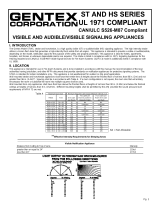
Caractéristiques sonores directionnelles :
pour un avertisseur et un avertisseur/stroboscope
Angle horizontal
-3 dBA 155 et 55
-6 dBA
Angle vertical
-3 dBA 150 et 55
-6 dBA 150
CARACTÉRISTIQUES SONORES NOMINALES EN DÉCIBELS DANS
UNE CHAMBRE ANÉCHOÏQUE ULC (dBA à 3 mètres)
POUR UN AVERTISSEUR
Mode de l’avertisseur Tension stabilisée minimum
de 24VRDA Caractéristiques
nominales dBnps
Temp. 3 520 Hz (NORMAL)* 84.7 dBA
Temp. 3 520 Hz (FORT)* 88.3 dBA
Temp. 4 520 Hz (NORMAL)* 84.7 dBA
Temp. 4 520 Hz (FORT)* 88.3 dBA
Page 4
GARANTIE LIMITÉE
Potter Electrical Signal Company, LLC garantit à l’acheteur initial que, dans des conditions normales d’utilisation et d’entretien, l’appareil sera exempt de tout défaut de fabrication ou de matériaux pendant 60 mois à
compter de la date de fabrication (ou pendant aussi longtemps que l’exigent les lois applicables).
Cette garantie est nulle et sans effet lorsque les dommages ou la défectuosité sont attribuables : à un accident, un usage abusif, un abus, une utilisation anormale, une installation fautive, un
contact avec un liquide, un incendie, un séisme ou toute autre cause externe; à l’utilisation de l’appareil en dehors des directives établies par Potter Electrical Signal Company, LLC; à l’entretien,
la modification, la maintenance ou la réparation effectuée par toute autre entreprise que Potter Electrical Signal Company, LLC. Cette garantie ne transfère pas aux propriétaires ou acheteurs
ultérieurs de cet appareil. Cette garantie ne s’applique pas non plus : aux pièces consomptibles, comme les piles; aux dommages cosmétiques, y compris, mais sans en exclure d’autres, aux
égratignures ou bosses; aux défaillances attribuables à l’usure normale ou au vieillissement normal de l’appareil; si le numéro de série de l’appareil a été supprimé ou altéré.
DANS LES LIMITES AUTORISÉES PAR LA LOI, LA PRÉSENTE GARANTIE ET LES RECOURS QUI Y SONT DÉFINIS SONT EXCLUSIFS ET REMPLACENT TOUTE AUTRE GARANTIE, RECOURS ET
CONDITION, QU’ELLES SOIENT ORALES, ÉCRITES, LÉGALES, EXPRESSES OU IMPLICITES. POTTER ELECTRIC SIGNAL COMPANY, LLC DÉCLINE TOUTE GARANTIE LÉGALE ET IMPLICITE, Y
COMPRIS, MAIS NON DE FAÇON LIMITATIVE, TOUTE GARANTIE DE COMMERCIALITÉ OU D’ADAPTATION À UN USAGE PARTICULIER AINSI QUE LES GARANTIES CONTRE LES VICES CACHÉS OU
LES DÉFAUTS LATENTS, DANS LES LIMITES AUTORISÉES PAR LA LOI. DANS LA MESURE OU CES GARANTIES NE PEUVENT ETRE REJETEES, ET DANS LA MESURE PERMISE PAR LA LOI
APPLICABLE, TOUTE GARANTIE IMPLICITE S’APPLIQUE UNIQUEMENT À LA PÉRIODE DE GARANTIE INDIQUÉE PLUS HAUT. À NOTER QUE CERTAINS ÉTATS (PAYS ET PROVINCES/TERRITOIRES)
N’ACCEPTENT PAS LES LIMITATIONS QUANT À LA DURÉE DES GARANTIES (OU DES CONDITIONS) IMPLICITES. IL SE PEUT DONC QUE LES LIMITATIONS CI-DESSUS NE S’APPLIQUENT PAS
DANS VOTRE CAS. DANS LA MESURE OÙ CELA N’EST PAS EXCLU DANS LA PRÉSENTE GARANTIE ET DANS LES LIMITES AUTORISÉES PAR LA LOI, POTTER ELECTRICAL SIGNAL COMPANY, LLC
NE POURRA ÊTRE TENU RESPONSABLE DES DOMMAGES DIRECTS, SPÉCIAUX, INDIRECTS OU CONSÉCUTIFS DÉCOULANT DE TOUTE CONDITION OU BRIS DE LA GARANTIE OU PORTANT
SUR LA VENTE, L’UTILISATION OU LA RÉPARATION DE L’APPAREIL, OU DE TOUTE AUTRE THÉORIE LÉGALE, Y COMPRIS, MAIS NON DE FAÇON LIMITATIVE, DE LA PERTE D’USAGE, DE
REVENUS OU DE PROFITS RÉELS OU ANTICIPÉS, DE LA PERTE D’UTILISATION DES FONDS, D’AFFAIRES OU D’OCCASIONS, DE LA PERTE DE CLIENTÈLE OU DE L’ATTEINTE À LA RÉPUTATION.
LA RESPONSABILITÉ MAXIMALE DE POTTER ELECTRICAL SIGNAL COMPANY, LLC NE PEUT EN AUCUN CAS ÊTRE SUPÉRIEURE AU PRIX D’ACHAT DE L’APPAREIL. VEUILLEZ NOTER QUE
CERTAINS ÉTATS (PAYS ET PROVINCES/TERRITOIRES) N’AUTORISENT PAS L’EXCLUSION OU LA LIMITATION DES DOMMAGES DIRECTS, ACCIDENTELS OU CONSÉCUTIFS, DE SORTE QUE LES
LIMITATIONS OU EXCLUSIONS CI-DESSUS POURRAIENT NE PAS S’APPLIQUER DANS VOTRE CAS.
Si un défaut de fabrication ou de matériau entraîne la défaillance de votre appareil pendant la période de garantie, vous devez le retourner à Potter Electrical Signal Company, LLC, port payé, à l’adresse
suivante : Potter Electrical Signal Company, LLC, 1609 Park 370, Hazelwood MO 63042. Vous devez apporter la preuve de la date d’achat de l’appareil, à la satisfaction de Potter Electric Signal Company, LLC.
Vous devez aussi fournir votre adresse pour le retour de l’appareil. Le service sous garantie peut être uniquement exécuté par le personnel de Potter Electric Signal Company, LLC, dans les installations de
Potter Electric Signal Company, LLC’s de Hazelwood au Missouri. Il faut aussi emballer soigneusement l’appareil pour réduire au minimum les risques de dommage pendant le transport. Si nous recevons un
appareil endommagé en cours de transport, nous vous en aviserons et il vous reviendra d’obtenir dédommagement de la part du transporteur.
Si vous transmettez une demande valable à Potter Electrical Signal Company, LLC pendant la période de garantie, Potter Electrical Signal Company, LLC assumera, sans frais et à sa discrétion, la
réparation de votre appareil ou vous fournira un appareil neuf ou remis à neuf; vous n’aurez qu’à assumer les frais d’acheminement de l’appareil par la poste. Potter Electrical Signal Company, LLC ne
s’engage pas à rembourser les frais des pièces de rechange ou des réparations effectuées par d’autres parties. L’appareil réparé ou de remplacement vous sera retourné sans frais et il sera couvert en
vertu de la garantie pendant la période de garantie résiduelle, le cas échéant. Lors du remplacement d’un produit ou d’une pièce, l’élément de remplacement devient votre propriété tandis que l’élément
remplacé devient la propriété de Potter Electrical Signal Company, LLC. Pour de plus amples renseignements sur la garantie ou le produit, visitez www.pottersignal.com.
LA PRÉSENTE GARANTIE VOUS ACCORDE DES DROITS PARTICULIERS, MAIS IL SE POURRAIT QUE VOUS AYEZ AUSSI D’AUTRES DROITS, QUI VARIENT D’UN ÉTAT (OU PAYS OU
PROVINCE/TERRITOIRE) À L’AUTRE. DANS LA PRÉSENTE GARANTIE, POTTER ELECTRICAL SIGNAL COMPANY, LLC NE LIMITE PAS VOS DROITS ET N’EN EXCLUT AUCUN, DU MOINS DANS
LES LIMITES AUTORISÉES PAR LA LOI. POUR BIEN COMPRENDRE VOS DROITS, VOUS DEVRIEZ CONSULTER LA LÉGISLATION DE VOTRE PAYS, PROVINCE/TERRITOIRE OU ÉTAT.
* Temp 4 520 Hz mesuré conformément à la norme ANSI/UL 2075
AVIS :
LE CODE NATIONAL DU BÂTIMENT ET LA NORME
CAN/ULC S525 EXIGENT QUE TOUS LES
AVERTISSEURS DESTINÉS À L’ÉVACUATION DU
BÂTIMENT DIFFUSENT DES SIGNAUX TEMPORELS
CODIFIÉS.
LES APPAREILS ONT FAIT L’OBJET D’ESSAIS À 0 °C,
À 49 °C ET À UNE HUMIDITÉ DE 93 %.
LA CADENCE TEMPORELLE À QUATRE TONALITÉS
(TEMPORELLE 4) PEUT ÊTRE OBTENUE AVEC CE
PRODUIT LORSQU’IL UTILISÉ AVEC LE MODULE DE
SYNCHRONISATION GTSM OU LE PROTOCOLE DE
SYNCHRONISATION GTSM POTTER ELECTRIC.
= AUCUNE PERTE MESURÉE
OBTENIR LE DÉCIBEL DE CORNE CAN/ULC ET LES VALEURS NOMINALES DE COURANT POUR L'APPAREIL AUDITIF LFH-24, VOIR INFORMATIONS SUR
LA PAGE 1.
OBTENIR LE DÉCIBEL DE CORNE CAN/ULC ET LES VALEURS NOMINALES DE COURANT POUR L'APPAREIL AUDITIF LFHS-24, VOIR INFORMATIONS SUR
LA PAGE 2.
CARACTÉRISTIQUES SONORES NOMINALES EN DÉCIBELS DANS
UNE CHAMBRE ANÉCHOÏQUE ULC (dBA à 3 mètres)
POUR UN AVERTISSEUR/STROBOSCOPE
Mode de l’avertisseur Tension stabilisée minimum
de 24VRDA Caractéristiques
nominales dBnps
Temp. 3 520 Hz (NORMAL)* 88.2 dBA
Temp. 3 520 Hz (FORT)* 90.1 dBA
Temp. 4 520 Hz (NORMAL)* 87.1 dBA
Temp. 4 520 Hz (FORT)* 88.0 dBA
Date de publication du manuel :
02/01/15
Avis important :
Ces renseignements ont été préparés par Potter Electrical Signal Company, LLC (ci-après « Potter ») à titre informatif uniquement; ils sont de nature sommaire et ne constituent nullement des avis juridiques et ne doivent par conséquent pas être utilisés à une telle fin. À cet égard, Potter ne fait aucune
représentation ni garantie, explicite ou implicite, que ces renseignements sont exhaustifs et exacts, à jour, ou conformes aux lois, règlements ou règles locaux, provinciaux ou fédéraux. Ces renseignements ne tiennent pas compte de toutes les considérations juridiques, en raison des inévitables incertitudes quant
à l’interprétation des lois et règlements et à la mise en application de ces lois et règlements en fonction des situations particulières. Les activités de chaque personne peuvent modifier les obligations pertinentes en vertu des lois ou des règlements en vigueur. Par conséquent, ces renseignements ne doivent être
utilisés qu’à des fins informationnelles et ne doivent pas servir à remplace un avis juridique professionnel. Potter n’assumera aucune responsabilité quant aux mesures ou activités qui pourraient être, ou ne pas être, prises ou effectuées à la suite de ces renseignements.
Potter Electric Signal Company, LLC
1609 Park 370, Hazelwood, MO 63042
TÉLÉPHONE : +1 800-325-3936
www.pottersignal.com
550-0649-AAD
  • Page 1 1
  • Page 2 2
  • Page 3 3
  • Page 4 4
  • Page 5 5
  • Page 6 6
  • Page 7 7
  • Page 8 8

Potter LFH Series User manual

Type
User manual
This manual is also suitable for

Ask a question and I''ll find the answer in the document

Finding information in a document is now easier with AI

in other languages