Page is loading ...

©Copyright Task Force Tips LLC 2010-2022 1 LIA-500 March 28, 2022 Rev08
TASK FORCE TIPS LLC
MADE IN USA · tft.com
3701 Innovation Way, Valparaiso, IN 46383-9327 USA
800-348-2686 · 219-462-6161 · Fax 219-464-7155
G-Force
INSTRUCTION FOR INSTALLATION, OPERATION, AND MAINTENANCE
LDH VALVED APPLIANCES
DANGER
Understand manual before use. Operation of this device without understanding the manual and
receiving proper training is a misuse of this equipment. Obtain safety information at tft.com/
serial-number.
This equipment is intended for use by trained and qualified emergency services personnel for
firefighting. All personnel using this equipment shall have completed a course of education
approved by the Authority Having Jurisdiction (AHJ).
This instruction manual is intended to familiarize firefighters and maintenance personnel with the
operation, servicing, and safety procedures associated with this product. This manual should be
kept available to all operating and maintenance personnel.
OPERATING RANGE
Pressure Max 300 PSI
Pressure Min Full Vac.
HYDROSTATIC PROOF TEST
900 PSI

©Copyright Task Force Tips LLC 2010-2022 2 LIA-500 March 28, 2022 Rev08
The member companies of FEMSA that provide emergency
response equipment and services want responders to know and
understand the following:
1. Firefighting and Emergency Response are inherently
dangerous activities requiring proper training in their hazards
and the use of extreme caution at all times.
2. IT IS YOUR RESPONSIBILITY to read and understand
any user’s instructions, including purpose and limitations,
provided with any piece of equipment you may be called on
to use.
3. IT IS YOUR RESPONSIBILITY to know that you have been
properly trained in Firefighting and/or Emergency Response
and in the use, precautions, and care of any equipment you
may be called upon to use.
4. IT IS YOUR RESPONSIBILITY to be in proper physical
condition and to maintain the personal skill level required to
operate any equipment you may be called upon to use.
5. IT IS YOUR RESPONSIBILITY to know that your equipment is
in operable condition and has been maintained in accordance
with the manufacturer’s instructions.
6. Failure to follow these guidelines may result in death, burns or
other severe injury.
Fire and Emergency Manufacturers and Service Association, Inc.
PO Box 147, Lynnfield, MA 01940 • www.FEMSA.org
© 2020 FEMSA. All Rights Reserved.
PERSONAL RESPONSIBILITY CODE
DANGER
SUPPORTING MATERIALS
The following document contains supporting safety and operating information pertaining
to the equipment described in this manual.
LIA-202
Pressure Relief Valve Manual
©Copyright Task Force Tips LLC 2004-2019 LIA-202 November 12, 2019 Rev05
MANUAL: Pressure Relief Valve
INSTRUCTIONS FOR SAFE OPERATION AND MAINTENANCE
WARNING Understand manual before use. Operation of this device without understanding the manual and
receiving proper training is a misuse of this equipment. Obtain safety information at tft.com/
serialnumber.
This instruction manual is intended to familiarize re ghters and maintenance personnel with the operation, servicing, and safety
procedures associated with this product.
This manual should be kept available to all operating and maintenance personnel.
Flange Mounted PRV
Flange Mounted PRV
with Galvanic Isolator
Flange mounted PRVs are available with a variety of outlets. Consult the catalog, factory, or tft.com to nd the con guration for your
application.
TASK FORCE TIPS LLC
MADE IN USA • TFT.com
3701 Innovation Way, Valparaiso, IN 46383-9327 USA
800-348-2686 • 219-462-6161 • Fax 219-464-7155
©Copyright Task Force Tips, Inc. 2008-2016 LIA-355 May 26, 2016 Rev06
2.5" Hydrant Valve
AV5NJ-NJ
2.5" Slow Close Hydrant Valve
AV5NJ-NJ-SC
TASK FORCE TIPS, INC.
MADE IN USA • www.tft.com
3701 Innovation Way, Valparaiso, IN 46383-9327 USA
800-348-2686 • 219-462-6161 • Fax 219-464-7155
OPERATING RANGE
Pressure Max 300 PSI
Pressure Min Full Vac.
Hydrostatic
Proof Test:
900 PSI
MANUAL: 2.5” HYDRANT VALVE
INSTRUCTIONS FOR SAFE OPERATION AND MAINTENANCE
WARNING Understand manual before use. Operation of this device without understanding the manual and receiving
proper training is a misuse of this equipment. Obtain safety information at www.tft.com/serial-number
LIA-355
2.5” Hydrant Valve Manual

©Copyright Task Force Tips LLC 2010-2022 3 LIA-500 March 28, 2022 Rev08
TABLE OF CONTENTS
1.0 MEANING OF SAFETY SIGNAL WORDS
2.0 SAFETY
3.0 GENERAL INFORMATION
3.1 SPECIFICATIONS
3.2 VARIOUS MODELS AND TERMS
3.2.4 SLOW CLOSE VALVE (OPTIONAL)
3.3 CORROSION
3.4 USE WITH SALT WATER
4.0 INSTALLATION
4.1 MOUNTING THE APPLIANCE
4.2 CHANGING THE CRANK HANDLE OFFSET
4.3 STORZ SUCTION GASKET REQUEST
5.0 USE
5.1 VALVE OPERATION
5.2 AIR VENT AND WATER DRAIN
5.3 PRESSURE RELIEF VALVE (PRV)
5.3.1 RELIEF VALVE PRESSURE SETTING
5.4 PRESSURE LOSS
5.5 SUCTION SCREEN
6.0 WARRANTY
7.0 MAINTENANCE
7.1 TROUBLESHOOTING
7.2 SERVICE TESTING
7.3 REPAIR
8.0 EXPLODED VIEW AND PARTS LISTS
9.0 OPERATION AND INSPECTION CHECKLIST

©Copyright Task Force Tips LLC 2010-2022 4 LIA-500 March 28, 2022 Rev08
1.0 MEANING OF SAFETY SIGNAL WORDS
A safety related message is identified by a safety alert symbol and a signal word to indicate the level of risk involved with a particular
hazard. Per ANSI Z535.6, the definitions of the four signal words are as follows:
2.0 SAFETY
3.0 GENERAL INFORMATION
The products in the LDH Suite are lightweight, low friction-loss valves and manifolds that can be used in many water distribution
applications. The robust valve mechanism from the TFT Ball Intake Valve is combined with TFT’s 2.5” quarter-turn ball valves and
folding handles for the ultimate in versatility. Valve seats are field replaceable, and quarter-turn folding valve handles require low force to
move, even under pressure. Automatic valve lock on 2.5” valves maintains valve position while flowing at partial openings. Folding
handles minimize required storage space. Devices include a pipe threaded port for a pressure gauge. A polymer bearing ring prevents
galvanic corrosion on LDH couplings.
3.1 SPECIFICATIONS
Table 3.1
DANGER
DANGER indicates a hazardous situation which, if not avoided, will result in death or serious injury.
WARNING
WARNING indicates a hazardous situation which, if not avoided, could result in death or serious
injury.
CAUTION CAUTION indicates a potentially hazardous situation which, if not avoided, could result in minor
or moderate injury.
NOTICE
NOTICE is used to address practices not related to physical injury.
DANGER
An inadequate supply of pressure and/or flow will cause an ineffective stream and can result
in injury or death. Choose operating conditions to deliver adequate fire suppression.
WARNING
This equipment is intended for use by trained personnel for firefighting. Use of this equipment for
other purposes may involve hazards not addressed by this manual. Seek appropriate guidance and
training to reduce risk of injury.
WARNING
Equipment may be damaged if frozen while containing significant amounts of water. Such damage
may be difficult to detect visually. Subsequent pressurization can lead to injury or death. Any time
the equipment is subject to possible damage due to freezing, it must be tested and approved for
use by qualified personnel before being considered safe for use.
WARNING
Sudden changes in valve position can cause pressure spikes (water hammer) and could lead to
hose or pipe failure or an out of control monitor. Open and close the valve slowly to avoid water
hammer.
WARNING
Interrupting flow to the device could cause injury or death. Avoid situations that may interrupt
flow to the device such as: hose line kinks, traffic running over hose, and automatic doors or
devices that can pinch the hose.
NOTICE
To prevent mechanical damage, do not drop or throw equipment.
MODEL STANDARD METRIC
LDH Waterway Size (at valve seat) 3.65” 93 mm
LDH Valve Meets NFPA Slow Close Requirement
Auxiliary Waterway Size 2.5” 63.5 mm
Maximum Operating Pressure 300 psi 20 bar
Hydrostatic Proof Test Pressure 900 psi 62 bar
Operating Temperature Range of Fluid 33° to 120°F 0° to 50°C
Storage Temperature Range* -40° to 150°F -40° to 65°C
Materials Used Aluminum 6000 series hard anodized MIL8625 class 3 type 2,
stainless steel 300 series
* For temperatures below 32°F (0°C), valves must be drained after use to avoid damage.

©Copyright Task Force Tips LLC 2010-2022 5 LIA-500 March 28, 2022 Rev08
3.2 VARIOUS MODELS AND TERMS
Figure 3.2A
Figure 3.2B
Figure 3.2C
IN-LINE VALVE
ALA CARTE
AIR VENT/
DRAIN
PART# A1621-KIT
VALVE POSITION
INDICATOR
CRANK
ALA CARTE
PRESSURE
RELIEF VALVE
PART# A1809
IN-LINE VALVE
CRANK
SIDE B
CARRYING HANDLE
SIDE A
(SEAL SIDE)
VALVE POSITION
INDICATOR
THREE-WAY VALVED MANIFOLD
FOUR-WAY VALVED MANIFOLD
PRESSURE
RELIEF VALVE
SIDE A
(SEAL SIDE)
SIDE A
(SEAL SIDE)
OPENCLOSED OPENCLOSED
FOLDING
HANDLES
OPEN
CLOSED
OPEN
CLOSED
FOLDING
HANDLES
SIDE B
FOLDING
HANDLES
SIDE A
(SEAL SIDE)
PRESSURE
RELIEF
VALVE
OPEN
CLOSED
OPENCLOSED
LDH WATER THIEF

©Copyright Task Force Tips LLC 2010-2022 6 LIA-500 March 28, 2022 Rev08
3.2.4 SLOW CLOSE VALVE (OPTIONAL)
2-1/2" Valves may be equipped with either a quarter turn shutoff
handle, or a slow close operator knob.
To operate, turn the handle or knob the desired OPEN/CLOSED
direction indicated on the handle.
Slow close operators require 3-1/2" turns between the full closed
and full open positions. A valve position indicator in the center of the
knob is flush with the knob surface when the valve fully closed and
raises 1/2" when the valve is fully opened.
3.3 CORROSION
Aluminum parts are hard anodized. All castings are then powder coated inside and out to help prevent corrosion. Most hose couplings
are attached using polymer bearing rings which provide electrical insulation to help prevent galvanic corrosion. The effects of corrosion
can be minimized by good maintenance practice.
3.4 USE WITH SALT WATER
Use with salt water is permissible provided the equipment is thoroughly cleaned with fresh water after each use. The service life of the
equipment may be shortened due to the effects of corrosion, and is not covered under warranty.
4.0 INSTALLATION
4.1 MOUNTING THE APPLIANCE
Make connections to fire hose or fittings on each side of the valved appliance.
4.2 CHANGING THE CRANK HANDLE OFFSET
When equipped with a crank handle, two offset positions are
available to adjust the swing radius of the crank and knob. The longer
offset position offers reduced effort to operate the valve. The shorter
offset is available to avoid interference with other equipment.
To change the offset:
1. Remove the two 1/4-20 x 1/2” button head cap screws from
the crank.
2. Place the crank in the desired position.
3. Replace the screws.
4.3 STORZ SUCTION GASKET REQUEST
If your application of this product requires drafting, you may need a suction gasket.
Please call 1-800-348-2686 to receive a free suction gasket by mail.
Part Numbers: 4” Storz - item #A4216, 5” Storz - item #A4221, 6” Storz - item #A4273.
CAUTION Mismatched or damaged waterway connections may cause equipment to leak or uncouple under
pressure. Failure could result in injury. Equipment must be mated to matched connections.
CAUTION Dissimilar metals coupled together can cause galvanic corrosion that can result in the inability to
uncouple the connection, or complete loss of engagement over time. Failure could cause injury. Per
NFPA 1962, if dissimilar metals are left coupled together, an anti-corrosive lubricant should be
applied to the connection and the coupling should be disconnected and inspected at least
quarterly.
Indicator flush
when fully closed
Valve postion indicator
raises 1/2” when valve
is fully opened
Figure 3.2.4
REINSTALL CRANK IN THIS HOLE
IF SHORTER SWING IS DESIRED
Figure 4.2

©Copyright Task Force Tips LLC 2010-2022 7 LIA-500 March 28, 2022 Rev08
5.0 USE
5.1 VALVE OPERATION
The valves covered by this manual utilize positive stops at the OPEN and CLOSED positions. Attempting to close a valve further than
the positive stops will not result in a tighter seal between the ball and valve seat. All valves include markings to indicate the direction of
handle rotation to open the valve.
Valves with quarter-turn handles will reach the positive stops when the handle is either parallel to the outlet (OPEN position) or
perpendicular to the outlet (CLOSED position).
Valves with hand cranks include a valve position indicator. To open the valve, turn the hand crank until the valve position indicator shows
OPEN. To close the valve, turn the hand crank the opposite way until the valve position indicator shows CLOSED.
Valves with slow close knobs (optional) include a valve position indicator in the center of the knob. To operate, turn the knob the desired
OPEN/CLOSED direction indicated. Slow close operators require 3-1/2" turns between the full closed and full open positions. The valve
position indicator is flush with the knob surface when the valve fully closed and raises 1/2" when the valve is fully opened.
Table 5.1
5.2 AIR VENT AND WATER DRAIN
This device may be equipped with an air vent/drain which will allow the air to escape from the valve when the hose is charged. The air
vent/drain may be added to the device by purchasing TFT Part # A1621-KIT.
The air vent/drain is opened by turning the knob counter-clockwise and closed by turning it clockwise.
To drain the water out of the valve after use, open the air vent/drain. A ½” diameter tube may be used to direct the drained water away
from the device.
NOTICE
Up to the maximum operating pressure, the torque required to operate the valve should never
exceed the values in the table below. Requiring greater torque than listed below is an indication that
the valve requires maintenance.
• Exceeding 30 ft-lb / 41 N·m torque may damage the appliance.
• Kicking or standing on the valve controls is considered misuse of the appliance.
Valve Seat Bore
Size
Maximum
Acceptable Torque
Maximum Acceptable Force
2.5” 63.5 mm 20 ft-lb 27 N·m 55 lb 25 kg 1/4-turn Handle
3.65” 93 mm 12 ft-lb 16 N·m 55 lb 25 kg Knob
NOTICE
For valves with parallel shaft gearboxes, exceeding 30 ft-lb/40 N-m torque will result in PERMANENT
DAMAGE to several components in the gearbox. The damage may not be outwardly obvious, but
could result in inability to operate the valve. To restore normal operation, the entire gearbox must
be replaced after relieving pressure from the valve.
CAUTION Loss of prime can interrupt water flow and cause injury or death. Always bleed out air with air
vent/drain to prevent possible loss of prime.

©Copyright Task Force Tips LLC 2010-2022 8 LIA-500 March 28, 2022 Rev08
5.3 PRESSURE RELIEF VALVE (PRV)
LDH valved appliances may be equipped with a pressure relief valve that can be set to a pressure between 90 and 300 psi. Its function
is to protect the pump and supply hose from excess pressure. The pressure relief valve may be added to the device by purchasing TFT
Part # A1809.
The relief valve may be mounted with its opening facing the front, back, right, or left. A piece of hose or tubing may be mounted on the
round spout to direct water coming out of the relief valve away from the device. To change the orientation of the relief valve, remove the
four 7/16” bolts on the corners of the relief valve flange, orient the valve in the desired position, and replace the bolts. Use thread-locking
compound on the threads of the bolts to prevent loosening due to vibration.
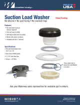
5.3.1 RELIEF VALVE PRESSURE SETTING
To set the relief valve pressure turn the adjusting screw on
the relief valve housing until the surface of the screw is even
with the desired pressure. A 9/16” (14 mm) socket or a 1/4”
hex key may be used to turn the adjusting screw. The
pressure relief valve should not be disabled (IE: capped,
plugged, or set to the OFF position) for normal service
conditions. Disabling the relief valve may result in system
damage or hose rupture if the system exceeds operating
limits. The pressure relief valve meets the requirements of
NFPA 1901.
WARNING
The Pressure Relief Valve is disabled in the OFF position and offers no system protection against
over-pressurization. Avoid water hammer or other pressure spikes during pump tests. Ensure PRV
is returned to its normal pressure setting following pump testing.
Adjusting Screw
Relief Valve
Discharge Opening
Table 5.3.1

©Copyright Task Force Tips LLC 2010-2022 9 LIA-500 March 28, 2022 Rev08
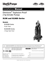
5.4 PRESSURE LOSS
Figure 5.4
5.5 SUCTION SCREEN
This device may be equipped with a suction screen to catch debris larger than 3/8” diameter in the waterway. See chart in section 5.4
PRESSURE LOSS to determine additional loss caused by the screen. To add or replace a suction screen, order TFT Part # A1410-KIT.
0
2
4
6
8
10
12
14
16
18
20
22
24
26
0 200 400 600 800 1000 1200 1400 1600 1800 2000
FLOW (GPM)
LOSS (PSI)
0
0.5
1
1.5
2
0 1000 2000 3000 4000 5000 6000 7000
FLOW (L/min)
LOSS (BAR)
LDH Waterway
with Suction Screen
2.5"
Waterway
LDH
Waterway

©Copyright Task Force Tips LLC 2010-2022 10 LIA-500 March 28, 2022 Rev08
6.0 WARRANTY
Task Force Tips LLC, 3701 Innovation Way, Valparaiso, Indiana 46383-9327 USA (“TFT”) warrants to the original purchaser of its
products (“equipment”), and to anyone to whom it is transferred, that the equipment shall be free from defects in material and
workmanship during the five (5) year period from the date of purchase. TFT’s obligation under this warranty is specifically limited to
replacing or repairing the equipment (or its parts) which are shown by TFT’s examination to be in a defective condition attributable to
TFT. To qualify for this limited warranty, the claimant must return the equipment to TFT, at 3701 Innovation Way, Valparaiso, Indiana
46383-9327 USA, within a reasonable time after discovery of the defect. TFT will examine the equipment. If TFT determines that there is
a defect attributable to it, TFT will correct the problem within a reasonable time. If the equipment is covered by this limited warranty, TFT
will assume the expenses of repair.
If any defect attributable to TFT under this limited warranty cannot be reasonably cured by repair or replacement, TFT may elect to
refund the purchase price of the equipment, less reasonable depreciation, in complete discharge of its obligations under this limited
warranty. If TFT makes this election, claimant shall return the equipment to TFT free and clear of any liens and encumbrances.
This is a limited warranty. The original purchaser of the equipment, any person to whom it is transferred, and any person who is an
intended or unintended beneficiary of the equipment, shall not be entitled to recover from TFT any consequential or incidental damages
for injury to person and/or property resulting from any defective equipment manufactured or assembled by TFT.
It is agreed and understood that the price stated for the equipment is in part consideration for limiting TFT’s liability. Some states do not
allow the exclusion or limitation of incidental or consequential damages, so the above may not apply to you.
TFT shall have no obligation under this limited warranty if the equipment is, or has been, misused or neglected (including failure to
provide reasonable maintenance) or if there have been accidents to the equipment or if it has been repaired or altered by someone else.
THIS IS A LIMITED EXPRESS WARRANTY ONLY. TFT EXPRESSLY DISCLAIMS WITH RESPECT TO THE EQUIPMENT ALL
IMPLIED WARRANTIES OF MERCHANTABILITY AND ALL IMPLIED WARRANTIES OF FITNESS FOR A PARTICULAR PURPOSE.
THERE IS NO WARRANTY OF ANY NATURE MADE BY TFT BEYOND THAT STATED IN THIS DOCUMENT.
This limited warranty gives you specific legal rights, and you may also have other rights which vary from state to state.

©Copyright Task Force Tips LLC 2010-2022 11 LIA-500 March 28, 2022 Rev08
7.0 MAINTENANCE
TFT products are designed and manufactured to be damage resistant and require minimal maintenance. However, as the primary
firefighting tool upon which your life depends, it should be treated accordingly. The unit should be kept clean and free of dirt by rinsing
with water after each use. Any inoperable or damaged parts should be repaired or replaced before placing the unit in service. To help
prevent mechanical damage, do not drop or throw equipment.
In applications where appliances are left continuously connected to the apparatus or other devices or are used where water is trapped
inside the appliance, the appliance must be flushed with fresh water following each use and inspected for damage.
This appliance should be disconnected, cleaned and visually inspected inside and out at least quarterly, or as water quality and use may
require. Moving parts such as handles, valve ball and couplings should be checked for smooth and free operation. Seals shall be
greased as needed with Silicone based grease such as Molykote 112. Any scrapes that expose bare aluminum should be cleaned and
touched up with enamel paint such as Rust-Oleum. Replace any missing or damaged parts before returning to service.
Any equipment taken out of service due to failure should be returned to the factory for repair or replacement. If you have any questions
regarding the testing or maintenance of your valve, please call Task Force Tips at 800-348-2686.
7.1 TROUBLESHOOTING
Figure 7.1
7.2 SERVICE TESTING
In accordance with NFPA 1962, equipment must be tested a minimum of annually. Units failing any part of this test must be removed
from service, repaired and retested upon completion of the repair.
7.3 REPAIR
Factory service is available. Factory serviced equipment is repaired by experienced technicians, wet tested to original specifications,
and promptly returned. All returns require a Returns Goods Authorization (RGA) number. Call TFT service department at 1-800-348-
2686 to troubleshoot and, if needed, obtain an RGA and directions for return.
Repair parts and service procedures are available for those wishing to perform their own repairs. Task Force Tips assumes no liability for
damage to equipment or injury to personnel that is a result of user service. Contact the factory or visit the web site at tft.com for parts
lists, exploded views, test procedures and troubleshooting guides.
Performance tests shall be conducted on the equipment after a repair, or anytime a problem is reported to verify operation in accordance
with TFT test procedures. Consult factory for the procedure that corresponds to the model and serial number of the equipment. Any
equipment which fails the related test criteria should be removed from service immediately. Troubleshooting guides are available with
each test procedure or equipment can be returned to the factory for service and testing.
8.0 EXPLODED VIEW AND PARTS LISTS
Exploded views and part lists are available at tft.com/serial-number.
SYMPTOM POSSIBLE CAUSE REMEDY
Leaks Debris or damage in seal area Clean out debris and/or replace damaged parts
WARNING
It is the responsibility of service technicians to ensure the use of appropriate protective clothing
and equipment. The chosen protective clothing and equipment must provide protection from
potential hazards users may encounter while servicing equipment. Requirements for protective
clothing and equipment are determined by the Authority Having Jurisdiction (AHJ).
CAUTION Any alterations to the product or its markings could diminish safety and constitutes a misuse of
this product.
NOTICE
All replacement parts must be obtained from the manufacturer to assure proper performance and
operation of the device.

©Copyright Task Force Tips LLC 2010-2022 12 LIA-500 March 28, 2022 Rev08
TASK FORCE TIPS LLC
MADE IN USA · tft.com
3701 Innovation Way, Valparaiso, IN 46383-9327 USA
800-348-2686 · 219-462-6161 · Fax 219-464-7155
9.0 OPERATION AND INSPECTION CHECKLIST
BEFORE EACH USE, equipment must be inspected to this checklist:
1. All valves open and close fully and smoothly.
2. Waterway is clear of obstructions.
3. There is no damage to any thread or other connection.
4. All locks and hold-down devices work properly.
5. The pressure setting on the relief valve (if so equipped) is set correctly.
6. Gaskets are in good condition.
7. There is no obvious damage such as missing, broken or loose parts.
8. There is no damage to the appliance (e.g. dents, cracks, corrosion, or other defects that could impair operation).
9. All swiveling elements rotate freely.
10. There is no corrosion on any surface.
11. There are no missing, worn out or broken lugs on couplings.
12. Hose is securely attached.
BEFORE BEING PLACED BACK IN SERVICE, equipment must be inspected to this list:
1. All valves open and close smoothly and fully.
2. The waterway is clear of obstructions.
3. There is no damage to any thread or other type connection.
4. The pressure setting on the relief valve (if so equipped) is set correctly.
5. All locks and hold-down devices work properly.
6. Internal gaskets are in good condition
7. There is no damage to the appliance (e.g., dents, cracks, corrosion, or other defects that could impair operation).
8. All swiveling connections rotate freely.
9. There are no missing parts or components.
10. The marking for maximum operating pressure is visible.
11. There are no missing, broken, or worn lugs on couplings.
WARNING
Equipment failing any part of the checklist is unsafe for use and must have the problem corrected
before use or being placed back into service. Operating equipment that has failed the checklist is a
misuse of this equipment.
/