
How to Use Your
Cobra 25 NW
Contents
Features
...........................................................................................1
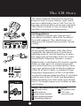
The CB Story..................................................................................A1
FCC Regulations
FCC Warnings
Included Accessories
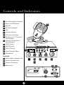
Controls & Indicators................................................................A2
Our Thanks to You ......................................................................A3
Customer Support
Installation
Location.......................................................................................2
Mounting and Connection...................................................2
Antennas
CB Antenna ................................................................................6
Marine Installation...................................................................6
Ignition Noise Interference ...................................................7
Operating Your 25 NW
Turning On Your CB.................................................................8
Setting Channel Selector.......................................................9
To Receive ...................................................................................10
Selecting a Channel ................................................................10
S-Meter.........................................................................................11
Dimmer Control........................................................................12
RF Gain Control.........................................................................12
Setting Squelch.........................................................................13
To Transmit .................................................................................15
Setting Dynamike ....................................................................16
Transmit.......................................................................................17
RF Meter ......................................................................................17
External Speaker.......................................................................18
PA (Public Address)..................................................................19
ANL (Automatic Noise Limiter) Switch.............................21
NB, OFF (Noise Blanker) Switch...........................................21
Temporary Mobile Set-Up.....................................................22
Home And Office Set-Up.......................................................23
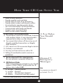
How Your CB Can Serve You...................................................25
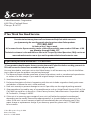
A Few Rules You Should Know............................................25
Channel 9 Emergency Messages .......................................25
CB 10 Codes...............................................................................27
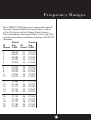
Frequency Ranges......................................................................29
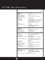
25 NW Specifications................................................................30
Warranty Information ..............................................................31
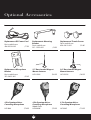
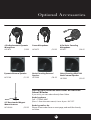
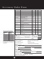
Optional Accessories.................................................................32
Order Form ....................................................................................34
If You Think You Need Service .............................Back Cover
Features of This Product
• 40 CB Radio Channels
• Heavy-Duty Dynamic
Microphone
• Full 4 Watts AM RF Power Output
• Instant Channel 19 and 9
• Front Panel 4-Pin Microphone
Connector
• Switchable Noise Blanker
• Switchable Automatic
Noise Limiter
• Adjustable Dynamike Boost
• Tactile Controls
• Illuminated Front Panel
• Dimmer Control
• RF Gain
• 9 ft. mic cord
1
CAUTION: TO REDUCE THE RISK OF ELECTRIC
SHOCK DO NOT REMOVE COVER (OR BACK)
NO USER SERVICEABLE PARTS INSIDE
REFER SERVICING TO QUALIFIED SERVICE
PERSONNEL
CAUTION
RISK OF ELECTRIC SHOCK
DO NOT OPEN
!
!

Installation
Location
2
Mounting and
Connection
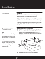
Mounting and Connection
Hold the radio with the mounting bracket in
the exact desired location. If there is no inter-
ference, remove the bracket and use it as a
template to mark the location for the mount-
ing screws.
Location
Plan location of transceiver and microphone
bracket before starting the installation.
Select a location that is convenient for operation,
yet does not interfere with the driver or passenger.
The transceiver is usually mounted to the under-
side of the dash with the microphone bracket
beside it.
Note
The transceiver is held in the
universal mounting bracket by
two thumbscrews which allow
for adjustment at a convenient
angle.
The bracket includes two self-
tapping screws and star wash-
ers.The mounting must be
mechanically strong, conve-
niently located.
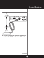
Drill the holes and secure the bracket.
2
1
CB Transceiver

Installation
3
continued
Connect the antenna cable plug to the recep-
tacle marked “ANT” on the back of the unit.
3
ANT
PA.SP. EXT.SP.
+POWER—
FCC ID:BBO3K229LTD
COBRA
MADE IN CHINA
SERIAL NO.:806135776
PRECISION ENGINEERED PRODUCT OF
COBRA ELECTRONICS CORP. CHICAGO, ILL.60707

Installation
4
Note
Before installing the CB radio,
visually check the vehicle’s
battery connection to deter-
mine which terminal, positive
or negative,is grounded (pos-
itive is the larger of the two)
to the engine block (or chas-
sis). A negatively grounded
vehicle has its negative lead
grounded to the chassis.
Note
Connecting to an accessory fuse
prevents the unit from being left
on accidentally,and also per-
mits operating the unit without
running the engine.
Note
In positive ground vehicles the
red wire goes to the chassis and
the black wire is connected to
the ignition switch.
In a negative grounded vehicle, connect the
red lead of the DC power cord to an accessory
12 volt fuse.
Connect the black lead to the negative side of
the vehicle.This is usually the chassis. Any con-
venient location with a good electrical contact
(remove paint) may be used.
4
5

Installation
5
Microphone
Connector
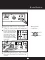
Plug power cable into back of unit marked
“Power”. Be sure to observe polarity markings.
Mount the microphone
bracket on the right side
of the unit (driver’s left)
using two screws sup-
plied. Bracket should be
placed under the dash
so microphone is readily
accessible.
6
7
Attach the 4-pin microphone cable to recepta-
cle on front of unit and Install unit in bracket
securely.
8
ANT
PA.SP. EXT.SP.
+POWER–
TE OF
JUNE 98
FCC ID:BBO3K229LTD
COBRA
MADE IN CHINA
806135776
PRECISION ENGINEERED PRODUCT OF
ELECTRONICS CORP. CHICAGO, ILL.60707
SIG 1 3 5 7 9 +30dB
RF
MIN MAX MIN MAXOFF
SHIELD
AUDIO
RX
TX
1
2
3
4

ANT
PA.SP. EXT.SP.
+POWER—
FCC ID:BBO3K229LTD
COBRA
MADE IN CHINA
SERIAL NO.:806135776
PRECISION ENGINEERED PRODUCT OF
COBRA ELECTRONICS CORP. CHICAGO, ILL.60707
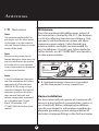
Antennas
CB Antenna
Since the maximum allowable power output of
the transmitter is limited by the FCC, the antenna
is critical in affecting transmission distance. Only
a properly matched antenna system will allow
maximum power output. Cobra loaded type
antenna models are highly recommended for
most installations. Consult your Cobra dealer for
further details, or call 773.889.3087 and speak to
a Cobra representative.
Marine Installation
The transceiver will not operate at maximum effi-
ciency in a boat without a ground plate, (unless it
has a steel hull). Before attempting installation ,
consult your dealer for information regarding an
adequate grounding system and prevention of
electrolysis between fittings in the hull and water.
CB Antenna
Note
For optimum performance in
passenger cars the ideal anten-
na location is on the center of
the roof. Second choice is on the
center of the trunk.
Note
Because many newer trucks
feature fiberglass door skins,the
outside mirror must be ground-
ed to the chassis via a ground
strap, if the antenna is mounted
on the mirror bracket.
Note
3-way Combination Antennas
are also available which allow
operation of all three bands
(AM-FM & CB), using a single
antenna.However,this type of
antenna usually results in less
than normal transmit and
receive range when compared
to a standard-type “Single
Band” CB antenna. Call
773.889.3087 for further infor-
mation.
6
1
A standard antenna connector is provided
on the transceiver for easy connection.

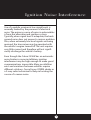
Ignition Noise Interference
Use of a mobile receiver at low signal levels is
normally limited by the presence of electrical
noise.The primary source of noise in automobiles
is from the alternator and ignition system.
Typically, when signal level is adequate, the back-
ground noise does not present a serious problem.
Also, when extremely low level signals are being
received, the transceiver may be operated with
the vehicle’s engine turned off.The unit requires
very little current and therefore will not signifi-
cantly discharge the vehicle’s battery.
Even though the Cobra 25 NW has an automatic
noise limiter, in some installations ignition
interference may be high enough to make good
communications impossible. Many possibilities
exist and variations between vehicles require
different solutions. Consult your COBRA dealer or
a 2-way radio technician for help in locating the
source of a severe noise.
7

The CB/PA button should be in the
CB position.
Operation
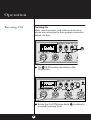
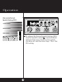
Turning On
8
Turning On
Make sure the power cord, antenna and micro-
phone are connected to their proper connectors
before starting.
2
SIG 1 3 5 7 9 +30dB
RF
MIN MAX
MIN MAX
OFF
25 NW LTD CLASSIC
1
Rotate the On/Off Volume knob clockwise to
a normal listening level.
LTD CLASSIC

Operation
9
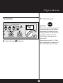
Setting Channel
Selector
Setting Channel Selector
Select one of forty channels and adjust
volume.The selected channel is indicated by
the LED readout directly above the channel
selector knob
1
MIN MAX
MIN MAX
O
LTD CLASSIC

Rotate the On/Off Volume knob clockwise
the green RX/TX LED will be illiuminated.
Operation
10
Switch to NOR to select desired channel.
1
Selecting A
Channel
Selecting A Channel
Note
Switch to 9 (Emergency) or 19
(Information) for instant access
to these channels.
25 NW
LTD CLASSIC
To Receive
1
To Receive
LTD CLASSIC

Operation
11
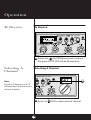
S-Meter
S-Meter
Swings proportionately to strength of incoming
signal when receiving.

Operation
12
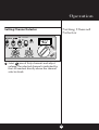
RF Gain Control
Dimmer Control
RF Gain Control
The RF Gain is used to optimize reception in
strong or weak signal areas.
Dimmer Control
Note
The RF Gain is used to optimize
reception in weak signal areas.
Rotate the DIM knob clockwise for
maximum brightness; counter-clockwise
for minimum.
Rotate the RF Gain knob counterclockwise
to reduce gain in strong signal areas. In weak
signal areas turn clockwise to increase gain.
SIG 1 3 5 7 9 +30dB
RF
MIN MAX
MIN MAX
OFF
25 NW
LTD CLASSIC
1
1
Note
The Dim controls the brightness
of the front panel, signal strength
meter and channel display.
SQL
MIN MAX
MIN MAX
O
LTD CLASSIC

Operation
13
NOISE
WEAK SIGNALS
MEDIUM SIGNALS
STRONG SIGNALS
G AT E C LO SE D
NOISE
WEAK SIGNALS
MEDIUM SIGNALS
STRONG SIGNALS
NOISE
WEAK SIGNALS
MEDIUM SIGNALS
STRONG SIGNALS
G AT E
O P E N
NOISE
WEAK SIGNALS
MEDIUM SIGNALS
STRONG SIGNALS
Gate open
Gate closed
Setting Squelch
Full clockwise rotation closes the gate
allowing only very strong signals to enter.
Full counterclockwise rotation opens the
“gate”allowing all signals in.
Setting Squelch
Squelch is the “control gate”for incoming signals.
2
1
SIG 1 3 5 7 9 +30dB
RF
MIN MAX
MIN MAX
OFF
CLASSIC
SIG 1 3 5 7 9 +30dB
RF
MIN MAX
MIN MAX
OFF
LTD CLASSIC

To achieve the Desired Squelch Setting (DSS),
turn the Squelch control counterclockwise
until you hear noise. Now turn the control
clockwise just until the noise stops. This is the
DSS setting.
14
Operation
3
NOISE
WEAK SIGNALS
MEDIUM SIGNALS
STRONG SIGNALS
G AT E
Gate set to Desired
Squelch Setting (DSS)
SIG 1 3 5 7 9 +30dB
RF
MIN MAX
MIN MAX
OFF
LTD CLASSIC

15
Operation
To Transmit
To Transmit
Caution!
Be sure the antenna is properly
connected to the radio before
transmitting. Prolonged trans-
mitting without an antenna, or
a poorly matched antenna,
could cause damage to the
transmitter.
Be sure to read the F.C.C. Rules
and Regulations included with
this unit before transmitting.
Select desired channel.
1
SIG 1 3 5 7 9 +30dB
RF
MIN MAX
MIN MAX
OFF
LTD CLASSIC

Setting Dynamike
This controls the microphone sensitivity
(outgoing audio level).
16
Setting
Dynamike
Operation
1
Initially, set fully clockwise so that maxi-
mum voice volume is available. Dynamike
may have to be reduced in some conditions.
SIG 1 3 5 7 9 +30dB
RF
MIN MAX
MIN MAX
OFF
LTD CLASSIC

17
Operation
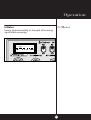
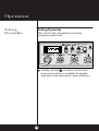
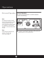
Transmit
Push and hold mic button to transmit.
Transmitter is now activated.When transmit-
ting, hold the microphone two inches from
your mouth and speak in a clear, normal voice.
Release to receive.
1
PUSH &
HOLD
Transmit
RF Meter
RF Meter
This meter swings proportionately to the RF
output (outgoing signal) while transmitting.

18
Operation
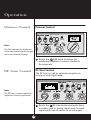
External Speaker
External Speaker
The external Speaker jack is used for remote
receiver monitoring.
Note
The external speaker should
have 8-ohm impedance and be
rated to handle at least 4.0
watts.When the external speak-
er is plugged in, the internal
speaker is automatically discon-
nected.
Note
Cobra external speakers are
rated at 15 watts.See
accessories page 33.
ANT
PA.SP. EXT.SP.
+POWER–
DATE OF
MFG :JUNE 98
FCC ID:BBO3K229LTD
COBRA
MADE IN CHINA
SERIAL NO.:806135776
PRECISION ENGINEERED PRODUCT OF
COBRA ELECTRONICS CORP. CHICAGO, ILL.60707
Connect an external speaker to the external
speaker jack on the rear panel.
1

19
Operation
PA (Public
Address)
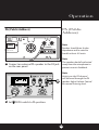
PA (Public Address)
Connect an external PA speaker to the PA jack
on the rear panel.
Note
Speaker should have 8-ohm
impedance and be rated to
handle at least 4.0 watts.
Note
The speaker should be directed
away from the microphone to
prevent acoustic feedback.
Note
Activity on the CB channel
will be heard through the PA
speaker.Adjust Volume Control
for normal listening level.
1
ANT
PA.SP. EXT.SP.
+POWER–
DATE OF
MFG :JUNE 98
FCC ID:BBO3K229LTD
COBRA
MADE IN CHINA
SERIAL NO.:806135776
PRECISION ENGINEERED PRODUCT OF
COBRA ELECTRONICS CORP. CHICAGO, ILL.60707
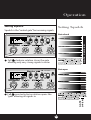
Set CB PA switch to PA position.
2
SIG 1 3 5 7 9 +30dB
RF
MIN MAX
MIN MAX
OFF
25 NW CLASSIC
LTD

Operation
20
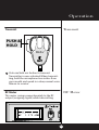
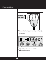
Push and hold microphone button and speak
in a normal voice.Your voice will sound on the
PA speaker.
Adjust PA speaker volume with the
Dynamike control.
3
4
SIG 1 3 5 7 9 +30dB
RF
MIN MAX
MIN MAX
OFF
LTD CLASSIC
PUSH &
HOLD
Page is loading ...
Page is loading ...
Page is loading ...
Page is loading ...
Page is loading ...
Page is loading ...
Page is loading ...
Page is loading ...
Page is loading ...
Page is loading ...
Page is loading ...
Page is loading ...
Page is loading ...
Page is loading ...
Page is loading ...
Page is loading ...
Page is loading ...
Page is loading ...
Page is loading ...
Page is loading ...
-
 1
1
-
 2
2
-
 3
3
-
 4
4
-
 5
5
-
 6
6
-
 7
7
-
 8
8
-
 9
9
-
 10
10
-
 11
11
-
 12
12
-
 13
13
-
 14
14
-
 15
15
-
 16
16
-
 17
17
-
 18
18
-
 19
19
-
 20
20
-
 21
21
-
 22
22
-
 23
23
-
 24
24
-
 25
25
-
 26
26
-
 27
27
-
 28
28
-
 29
29
-
 30
30
-
 31
31
-
 32
32
-
 33
33
-
 34
34
-
 35
35
-
 36
36
-
 37
37
-
 38
38
-
 39
39
-
 40
40


Ask a question and I''ll find the answer in the document
Finding information in a document is now easier with AI
Related papers
-
Cobra 2010 GTL WX Owner's manual
-
Cobra 29 NW User manual
-
-
Cobra 19 Ultra III Owner's manual
-
-
-
Cobra 19 DX IV Owner's manual
-
Cobra 29 LTD CHR User manual
-
-
Other documents
-
Cobra Electronics 29 LTD SE User manual
-
Sanyo TA 4100 Operating Instructions Manual
-
-
TTI Freequency TCB-880 User manual
-
Metra 44-UA200 Operating instructions
-
Realistic TRC-424 Owner's manual
-
-
-
Compaq A1500 User manual
-
PRESIDENT 1011001 Owner's manual