Page is loading ...

Originalinstructions
Usersmanual
MCD100G,MCD120G,MCD140G,MCD155G
Desiccantdehumidifier
withgasheaterforreactivation
Appliestoallunitsmanufactured
fromweek22,2013
190TEN–1081–J1408 ©MuntersEuropeAB2014

Impo rtan tuserinformation
Intendeduse
Munters dehumidifiers are intended to be used for the
dehumidificationofair.Anyotheruseoftheunit,or
use which is contrary to the instructions given in this
manual, can cause personal injury and damage to the unit
and other proper ty.
No modification of the unit is allowed without prior
approvalby Munters. Attachment or installation
of additional devic es is only allowed after written
agreement by Munters.
Warranty
Thewarrantyp
eriodisvalidfromthedatetheunit
left our f acto
ry, unless otherw ise stated in writing.
Thewarranty
is limited to a free exchange of parts or
components w
hich have failed as a result of defects in
materials o
rworkmanship.
All war ranty claims must include proof that the
fault has occurred within the warranty period an d
that the u n it has been used in accordance with the
specifications. All claims must specify the u nit type and
fabrication number. This infor mation is stamped on the
identification plate, see section Marking.
It is a condition of the war ranty that the unit for the full
warranty period is serviced and maintained by a qualified
Munters engineer or Munter s approved engineer.
Access to specific and calibrated test equipmen t is
necessary. The service and main tenance must be
documented for the warranty to be valid.
Alway s contact Munters for ser vic e or repair. Operating
faults can o ccur if the unit is maintained insufficiently or
incorrectly.
Safety
Information about dangers are in this manual indicated
by the common hazard symbol:
WARNING!
Indicatesapossibledangerthatcanleadtopersonalinjury.
CAUTIO N!
Indicatesapossibledangerthatcanleadtodamagetothe
unitorotherproperty,orc auseenvironmentaldamage.
NOTE!
Highlightssupplementaryinformationforoptimal
useoftheunit.
ConformitywithDirectives
The dehumidifier is in conformity with the essential
safety requirements of the Machinery Directive
2006/42/EC, the Low Voltage Directive 2006/95/EC
and the EMC Directive 2004/108/EC. The
dehumidifier is manufactured by a n ISO 9001:2008
accredited manufacturing org an isation.
Copyright
The contents of this manual can be changed without
prior notice.
NOTE!
Thismanualcontainsinformationwhichis
protectedbycopyrightlaws. Itisnotallowedtoreproduceor
transmitanypartofthismanualwithoutwrittenconsentfrom
Munters.
Please send any co mments regarding this manual to:
Munters Euro pe AB
Technical Documentation
P.O. Box 1150
SE- 164 26 KISTA Sweden
e-mail: t-doc@munters.se
ii
Importantuserinformation
190TEN–1081–J1408

Tableofconten ts
Importantuserinformation ............... ii
Intendeduse ...........................
ii
Warranty ...............................
ii
Safety ..................................
ii
ConformitywithDirectives ............
ii
Copyright ..............................
ii
Tableofcontents ........................... iii
1 Introduction ................................. 1
1.1 General ................................
1
1.2 Aboutthismanual .....................
1
1.3 Unintendeduse ........................
1
1.4 Safetyandcautions ...................
1
1.5 Operationmonitoring .................
3
1.6 Applicationlimitations .................
3
1.7 Faultindications .......................
3
1.8 Marking ................................
4
2 Dehumidifierdesign ....................... 5
2.1 Productdescription ...................
5
2.2 Principleofoperation ..................
5
2.3 Systemoverview ......................
7
2.3.1 Frontview ......................
7
2.3.2 Rearview .......................
8
2.4 Maincomponents,explodedview ....
9
2.5 Gasburnerunit ........................
10
2.6 GasMultiBloc
®
controlunit ............ 11
2.6.1 Principleofoperation ..........
11
2.6.2 Overview .......................
12
2.6.3 Lowpressureswitch ...........
12
2.7 Gascontrolvalveunit ................. 13
2.8 Burnersafetycontrolunit .............
14
2.8.1 Operation–start-up
sequence .......................
14
2.8.2 Programmeindicator ..........
15
2.8.3 Flamedetection ................
16
2.8.4 Shutdown/Lockout ............
16
2.9 Hightemperaturecut-out .............
16
2.10 Configurationfeatures ................
16
2.10.1Insulatedprocessairinlet .....
16
2.10.2Processfancontrol ............
16
2.10.3EnergyRecoveryPurge .......
18
3 Installation ................................... 19
3.1 Safety ..................................
19
3.2 General ................................
19
3.3 Inspectionofdelivery ..................
20
3.4 Movingthedehumidifier ..............
20
3.5 Storingthedehumidifier ..............
21
3.6 Siterequirements .....................
21
3.7 Splitunitinstallation ...................
21
3.7.1 Assembly .......................
23
3.7.2 Electricalconnections .........
25
3.8 Ductinstallation .......................
28
3.8.1 Generalrecommendations ... 28
3.8.2 Ductforoutdoorairinlet .......
29
3.8.3 Ductforwetairoutlet ...........
29
3.8.4 Ductconnectiondimensionsfor
inlets ............................
30
3.8.5 Ductconnectiondimensionsfor
fans .............................
31
3.9 Gasandairsupply .....................
33
3.10 Electricalconnections ................
33
3.11 Externalhumiditytransmitter .........
34
4 Commissioning ............................. 35
4.1 Pre-startchecks ....................... 35
4.2 Adjustmentofgasburner .............
35
4.3 Airflowadjustment ....................
37
4.3.1 General .........................
37
4.3.2 Settingtheratedairflows ......
37
4.3.3 Baseconfigurationsettings ...
38
4.4 Settingthegasburnereffect ..........
39
4.4.1 Settingmaximumeffect .......
39
4.4.2 Settingminimumeffect ........
40
5 Operation .................................... 41
5.1 Controlpanel ..........................
41
5.2 General ................................
42
5.3 Quickstop ..............................
42
5.4 Operatingtheunit .....................
43
5.4.1 Initialstart-up,Manualmode
(MAN) ...........................
43
5.4.2 Initialstart-up,Automatic
mode(AUTO)–regulatingto
set-point ........................
43
6 Serviceandmaintenance .................
44
190TEN–1081–J1408
Tableofcontents
iii

6.1 Safety ..................................
44
6.2 Regularserviceandmaintenance ...
44
6.3 Serviceoptions ........................
45
6.4 Extendedwarranty ....................
45
6.5 Serviceindicatorlamp ................
45
6.6 Serviceandmaintenanceschedule
(0–24000hours) .......................
46
6.7 Serviceandmaintenanceschedule
(28000–48000hours) .................
47
6.9 Maintenancescheduleforgasheater
unit .....................................
48
6.10 Airfilterreplacement ..................
49
6.10.1Preparation .....................
49
6.10.2Reactivationairfilter ...........
49
6.10.3Processairfilter ................
50
7 Faulttracing,gasheaterunit .............. 51
7.1 Faulttracinglist ........................
51
7.2 Measuringflamesignaland
differentialgaspressure ..............
53
8 Technicalspecification .................... 54
8.1 Capacitydiagrams ....................
54
8.2 Noisedata .............................
55
8.2.1 MCD100E ......................
55
8.2.2 MCD120E ......................
56
8.2.3 MCD140E ......................
57
8.2.4 MCD155E ......................
58
8.3 Dimensionsandservicespace .......
59
8.3.1 Dimensions ....................
59
8.3.2 Dimensionsforunitswithout
processfan .....................
60
8.3.3 Servicespace ..................
60
8.4 Technicaldata .........................
61
9 Scrapping .................................... 63
10 ContactMunters ............................ 64
iv
Tableofcontents
190TEN–1081–J1408

1 Introduction
1.1 General
Munters manufactures a w ide range of e fficient dehumidifiers designed for different uses and applications.
Contact your nearest Munters office if you have any questions reg a rding the installat ion or the use of your
dehumidifier.
For product data, see section Technical specification.
Reactivation using a gas heater means that natural g as or propane/LPG (option) is the source of energy
that is use d to reactivate the dehum idifier's rotor. This technique is intended for use where nat ural gas or
propane/LPG is available as a n alternative to heating with electricity or steam.
1.2 Aboutthismanual
This manual contains necessary information for how to install and use the dehumidifier in a safe and
efficient way. Information and guidelines for the operation of the control system can be found in a
supplementary document, also delivered with the dehumidifier.
NOTE!
Makesuretoreadallrelevantpartsofthismanualbeforeoperatingorperforminganyworkonthe
dehumidifier. Thismanualshouldbestoredinapermanentlocationclosetothedehumidifier.
1.3 U nintendeduse
The following restrictions on use apply:
■
Thedehumidifier is not intended for outdoor installation.
■
Thedehumidifier is not intended f or u se in classified areas where explosion safety compliant equipment
is requi red.
■
Thedehumidifier must not be installed near any heat g enerating devices that can cause damag e to the
equipment.
1.4 Safetyandcautions
Every measure has been taken in the design and manufacture of the dehumidifier to ensure that it meets the
safety requirements of the directives and standar ds listed in the EC Declaration of Conform ity.
The information in this manual shall in no way take precedence over individual responsibilities or local
regulations.
During ope
ration and other work with a machine it is always the responsibility of the individual to consider:
■
The safety of all persons concerned.
■
The safety of the unit and other proper ty.
■
The protection of the environment.
The types of dangers that are indicated in this manual are described in section Important user information.
190TEN–108 1–J1408
Introduction
1

WARNING!
-Theunitmustnotbesplashedwithorimmersedinwater.
-Donotconnecttheunittoothermainsvoltagethanspecifiedontheidentificationplate.
-Donotinsertfingersoranyotherobjectsintotheairvents.
-Allelectricalinstallationsmustbecarriedoutbyaqualifiedelectricianandinaccordancewithlocalregulations.
-Thedehumidifiercanrestartautomaticallyafterapowercut. Alwayssetandlockthemainpowerswitchinthe
OFFpositionbeforecarryingoutanyservicework.
-Useonlyapprovedlifting
equipmenttopreventpersonalinjuryanddamagetotheequipment.
-AlwayscontactMuntersforserviceorrepair.
WARNING!
Neverliftanassembledunitusingliftingeyeboltsattachedtothetopbox. Liftingeyeboltsmustonlybeusedfor
liftingthetopboxduringinstallationofasplitunit. Failuretoobservethiscancausepersonalinjuryanddamageto
theunit
The safety labels below are attached to the unit. Make sure that all personnel working with or near the unit
are aware of the meaning of each label.
Figure 1.1 Risk of p ersonal inju ry due to electric shock. Figure 1.2 R isk of personal injury due to hot surfaces.
TextonthesafetylabelinFigure 1.3 :
WARNING
Only lifting of top box permitted.
WARNING
!
Only lifting of top box permitted.
Refer to the user manual before lifting.
Figure 1.3 L ifting of unit not perm itted .
Refer to the user manual before lifting.
2
Introduction
190TEN–108 1–J 1408

1.5 Operationmonitoring
Thedehumidifier is controlled and monitored from the control panel on the front of the unit, see section
5.1, Control panel. The HMI (Human M achine Interface) is used to display values and parameters, and to
input settings and commands to the control system. The H MI is described in the se parate supplement.
1.6 Applicationlimitations
Thedehumidifier conforms to the emission limits of residential, commercial and light-industrial
environments except for the emission limits for harmonics emission (EN 61000–3–12). As the equipment
exceeds the limits for harmonics it may not be used in residential, commercial or light-industrial
environment without taking proper steps regarding the power installation like supplying the equipment
from a dedicated transformer connected to the high or medium voltage network.
Thedehumidifier may only be used in industrial environments (class A) w hen the HMI is equipped with a
touch panel. If the HMI is equipped with a text panel, the dehumidifiermaybeusedinallenvironments
since t he text panel is approved according to class B.
1.7 Faultindications
Any faults are indi
cated by the red light on the control panel. T he cause of the alarm is indicated on the
display.
190TEN–108 1–J1408
Introduction
3

1.8 Marking
Figur e 1.4 Position of identification plat e
15 kW
Max
15,7 kW
M
IP33
GAS
Munters Europe AB
Isafjordsgatan 1
164 26 Kista, Sweden
Made in Sweden
MCD140G
0910 170XXX XXXXX
Fabr. No.
Fabr. year 2009
3 ~ 400V 50 Hz
Type
Figure 1.5 Identification plate, example
Explanation of "Fabr. no" on the identification plate:
09: Year of manufacture
10: Week of manufacture
170XXX: Ar ticle number
XXXXX: Serial number
The label for the gas heater can be found next to the id entification plate on the unit.
AT-BE-DK-DE-ES-FI-FR-GB-GR-IE-IT-LU-NL-PT-SE
Qn:
Inlet pressure:
150 kW net.
B22-C12-C32
G20-G25
18-30 mbar
This unit must be installed in accordance with the rules in force.
Consult instructions before installation and use of this appliance.
Unit Gas Category:
Unit Categories:
Figure 1.6 Example of label for natural gas
AT-BE-DK-DE-ES-FI-FR-GB-GR-IE-IT-LU-NL-PT-SE
Qn:
Inlet pressure:
150 kW net.
B22-C12-C32
G31
18-30 mbar
This unit must be installed in accordance with the rules in force.
Consult instructions before installation and use of this appliance.
Unit Gas Category:
Unit Categories:
Figure 1.7 Example of label for propane (option)
4
Introduction
190TEN–108 1–J 1408

2 Deh umidifierdesign
2.1 Productdescription
The desiccant dehumidifier has been designed to effectively dehumidify the air in environments requiring
low air humidity.
All functional components are enclosed in a corrosion resistant Aluzink
®
casing (standard) or stainless steel
casing (option) which makes installation and maintenance easy. The unit is constructed on a steel base frame
which allows the use of a fork-lift truck during transportation and installation.
The electrical control system complies with standard EN 60204-1. The electrical components are mounted
on bus bars. The dehumidifier is manufactured according to E uropean standards and the established
requirements for CE-marking.
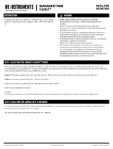
2.2 Principleofoperation
1
4
2
3
Figure 2.1 R otor principle
1. Process air
2. Dr y air
3. Reactivation air
4. Wet air
The desiccant rotor is the adsorption dehumidifying component in the unit. The rotor structure is
comprised of a large number of small air channels.
The desiccant rotor is made of a composite material that is highly effective in attracting and retaining water
vapour. The rotor is divided in two zones. The airflow to be dehumidified, process air, passes through the
largest zone of the rotor and then leaves the rotor as dry air. Since the rotor rotates slowly, the incoming air
always meets a dry zone on the rotor, thus creating a continuous dehumidification process.
Theairflow tha t is used to dry t he rotor, r e a c tivation air, is heated. T he reactivation air passes through
the rotor in the opposite direction to the process air and leaves the rotor a s wet air (warm, moist air). This
principle enables t he dehumidifier to work effectively, even at freezing temperatures.
The gas burner system used for reactivation is based on a burner operating on natural gas or propane/LPG
(option). The burner operates as a direct fired system to heat outdoor air to the required reactivation air
temp erature.
190TEN–108 1–J1408
Dehumidifierdesign
5

2
1
4
3
Figur e 2.2 Airflow overview
1. Process air
2. Dr y air
3. Reactivation air
4. Wet air
6
Dehumidifierdesign
190TEN–108 1–J 1408

2.3 Systemoverview
2.3.1 Frontview
3
5
7
3
6
9
1
2
8
4
Figure 2.3 Front view, main components
1. Filterbox,processair 6. Pressureswitchforreactivationair
2. Reactivationfanmotor 7. Hightemperaturecut-outswitch(HTCO)
3. Temperaturesensor,PT1000 8. Processfanmotor
4. Filterbox,reactivationair 9. Drivemotorforrotor
5. Burnersafetycontrolunit
190TEN–108 1–J1408
Dehumidifierdesign
7

2.3.2 Rearview
3
4
5
6
7
1
2
Figure 2.4 Rear view, main components
1. Controlpanel 5. Inspectionglass
2. Mainpowerswitch 6. GasMultiBloccontrolunit
3. Gasshut-offvalve 7. Gascontrolvalvewithactuator
4. Gasburner
8
Dehumidifierdesign
190TEN–108 1–J 1408

2.4 Maincomponents,explodedview
2
5
6
11
13
7
8
9
10
12
1
3
4
Figure 2.5 Main compo nents
1. Reactivationfan 8. Rotordrivemotor
2. Filter,reactivationair 9. Drivebelt
3. GastrainwithGasMultiBloccontrolunit 10. Rotor
4. Processfan 11. Rotorseal
5. Electricalpanel 12. Filterbox,processair
6. Gasburner 13. Filterbox,processair(option)
7. Temperaturesensor
190TEN–108 1–J1408
Dehumidifierdesign
9

2.5 Gasburnerunit
Direct fired gas burners are used on all MCD-series dehumidifiers. The burner operates on natural gas or
propane (option) and uses the reactivation air to supply the oxygen necessary for combustion. A c orrect
reactivation airflow is t h erefore essential to e n sure that the burner operates efficiently.
For optimal performance, the reactivation air must contain minimum 20 % oxygen. Bur ner return air cannot
be used. To maintain the efficiency of the unit, it is also important that the outlet for t he wet air is correctly
placed. This is to prevent the wet air contaminating the reactivation air.
The burner is mounted in the reactivation airflow. The gas is mixed with the reactivation air wh ich penetrates
into the space between the V-shaped mixing plates.
A spark ignitor and flame detection probe are mounted in the burner combustion chamber. The flame
detection probe uses the ionisation principle to send a flame signal to the burner safety control unit.
The working principle w ith constant airflow and pressure drop across the bur ner ensures that the
combustion gase s and reactivation air mix well.
4
2
1
6
3
5
Figure 2.6 Gas burner assembly
1. Mixing plates
2. End plate
3. Flame detection probe
4. Ignition transformer
5. Spark ignitor
6. Bur ner head
10
Dehumidifierdesign
190TEN–108 1–J 1408

6
8
2
4
5
3
7
1
Figur e 2.7 Side view of the burner
1. Bur ner head port
2. Flame detection probe
3. Mixing plates
4. Spark ignitor
5. Spark ignitor connection plug
6. Gas pipe
7. Flame detection connection plug
8. Silicone cable
2.6 G asMul tiBloc
®
controlunit
2.6.1 Principleofoperation
A GasMultiBloc control unit in the gas train controls and m onitors the gas pressure and flow. The
GasMultiBloc contains an adjustable flow regulator which in conjunction with an exter nal control valve
enables automatic modulation of the burner capacity, see Figure 2.9 .
L1
N
3
4
V1
V2
5
1
2
N
L1
Figure 2.8 Diagram, GasMultiBloc
3. Gas filter V1. Solenoid valve
4. Low pressure switch V2. Solenoid valve (including adjustable fl ow regulator)
5. Gas pressure regulator L1. Phase
N. Neutral
Theg asflows into the GasMultiBloc, passes through the gas filter (3) and the adjustable low pressure switch
(4). Valves V1 and V2 are energised by the same control signal and open simultaneously. The pressure is
set by the pressure regulator (5). The maximum allowed gasflow (max. burner capacity) is restricted by
the adjustable flow regulator included in valve V2.
190TEN–108 1–J1408
Dehumidifierdesign
11

2.6.2 Overview
1
8
5
2
3
4
6
7
9
A
B
Figure 2.9 O verview, GasMultiBloc
A. Flow from g a s supply B. F low to gas burner
1. Gas shut-off valve 6. C over plate for g as filter
2. L ow pressure switch 7. Screw for cover plate
3. P ressure test point for gas supply (P
e
) 8. P ressure test point (before valve V1)
4. Maximum flow adjustment knob 9. Gas control valve with actuator
5. Pressure test point (after valve V1)
2.6.3 Lowpressureswitch
The low pressure switch is connected to the inlet pipe on the GasMultiBloc control unit. If the gas pressure
is too low, the electrical supply to the control unit is disrupted. T he dehumidifier is then switched off
automatically, and an alarm for low gas pressure is shown on the control panel display. T he low pressure
switch has a range of 5 to 150 mbar. Standard setting is 15 mbar.
Made in Germany
IP 54
5
90
10
20
30
50
70
110
130
mbar
GW 50 A5
pmax.= 500 mbar Gas
~(AC) 50-60Hz 10A 250V
15T70
ID.No:CE-0085
AO 0012
150
Figur e 2.10 Low pressu re switch
12
Dehumidifierdesign
190TEN–108 1–J 1408

2.7 Gascontrolvalveunit
In this m o dulating gas reactiva tion heater system , there is a c ontrol va lve fitted in the g as line between the
GasMultiBloc and the gas burner. This makes it possible to vary the g a s flow and burner capacity during
operation. The control valve is connected to an electric actuator that is controlled by the program unit using
a 0 – 10V DC signal.
0
1
0
A
B
C
D
A. Rotating valve e xtension C. Ove rride button
B. Minimum capacity screw D. Inverse control action s witch
190TEN–108 1–J1408
Dehumidifierdesign
13

2.8 Burnersafetycontrolunit
The burner safety control unit is located in the electrical panel, see Figur e 2.3 .
The control unit ensures safe ignition, start -up and shut-dow n during both nor mal operation and if a fault
occurs.
It is equipped with a self-checking flame monitoring circuit that controls t he combustion process. T he flame
monitoring circuit applies the necessary safety measures if the flame signal occurs to soon or not at all, and if
any type of fault in the flame detector, detector cables or flame signal amplifier occurs.
Faults that are detected during the start-up procedure or normal operation result in shutdown. Operation is
then preven ted u ntil the fault is remedied and the bur ner safety control unit is reset using the mode switch.
See the wiring diag ram for more information o n the control unit connections.
1
2
Figure 2.11 Bur ner safety control unit
1. Programme indicator
2. Warning lamp for shutdown/lockout switch
2.8.1 Operation–start-upsequence
When power is applied to the relay and the start contact is closed, the burner control unit runs to ‘start’
position. When the burner control unit receives a start ing signal from the PLC, an automatic check is carr ied
out between the burner control unit a nd the pressure switch for the reactivation airflow. This is to ensure
that the pressure sw itch contact is open. If the contact is open, the reactivation air fan can star t .
■
If the pressure switch contact is closed (in the 'no air' position), the control unit does not star t.
Shortly after the reactivat ion air f an starts, the bur ner control unit checks that the pressure switch contact has
closed (combustion air supply available).
■
If the contact has not closed, the contr ol unit abor ts the burner start up .
When the flow sw itch contact is closed, the purge time start. For about 30 seconds, all remaining gasses are
purged from the c ombustion chamber. After the purge time has been terminated, the ignition is started.
A few seconds later the g as supply valves (V1 and V2) are supplied with power. In case a flame has been
established and detected by the flame probe, the relay continues to operate until it has reached it s run
position. If no flame is present or not detected, the relay generates a burner lock out, closing (V1 and V2)
immediately. The program indicator stops in t he position where the problem occurred as help for fault
tracing.
14
Dehumidifierdesign
190TEN–108 1–J 1408

2.8.2 Programmeindicator
The p r o gramm e indicator shows the status of the bur ne r. Since the progr am me indicator remains in the
position where shutdown occurs, it gives valuable inf ormation that facilitates fault tracing. T he different
situations causing shutdow n are indicated by the following symbols:
P
1
2
a
b
b
P
1
2
e
d
c
f
Figure 2.12 Pro
gramme indicator
Symbol Description
a–b Start-upsequence
..........
Durationofsafetytime
c Startposition
d Nostartwhenthecontactsforthereactivationairflowpressureswitchareclosed(noairposition)
e Lockout(faultintheflamesupervisioncircuit)
f Abortionofstart-upsequence(notinuseinthisapplication)
1 Lockout(noflame)
2 Lockout(noflame),highflame(notinuseinthisapplication)
P Lockout(noreactivationair)
190TEN–108 1–J1408
Dehumidifierdesign
15

2.8.3 Flamedetection
A flame detection probe is used to verify that a flam e is present. The detection probe consists of a metal
electrode which is positioned in the flame.
The burner's control unit senses the existence, or not, and condition of the flame during start-up and nor mal
operation. A flame fault always causes bur ner shutdown and lockout.
2.8.4 Shutdown/Lockout
When shutdown/lockout occurs, its cause must be remedied before the burner can be restarted
using the mode switch. To restar t t he burner, the mode switch must first be set to 0 and then to start.
Shutdown/Lockout can be due to the following:
■
Low pressure switch on the GasMultiBloc is defective or incorrectly set
■
The pressure switch for reactivation air is defective or incorrectly set
■
Gasvalvesfailtoopen
■
No ignition
■
Defect in the reactivation a ir fan
■
Flame fault (either at start-up or during normal operation)
See Table 7.1 for possible faults and t he r emedies that are required to reset the control unit.
2.9 Hightemperaturecut-out
The unit is equipped with a high temperature cut-out (HTC O), which prevents the unit from being
overheated and damaged if the reactivation air is too hot. The HTCO switches off the heater if the
temperature exceeds the HTCO setting.
The thermostat housing is located beside the electrical panel, see Figure 2.3 . A resetting button is located
on the back of the thermostat housing.
The HTCO bulb is located in the reactivation air duct. When the HTCO trips,the message "Heater high
temperature" is shown on the control panel display.
2.10 Configurati onfeatur es
This chapter
includes information a bout functions and components that can be added w hen ordering a
MX² dehumi
difier. At delivery, each unit is configured according to the config uration sheet supplied with
the user ma
nual.
2.10.1 Insulatedprocessairinlet
All dehumidifier units supplied with pre-cooled process air have insulated process air inlet. The process air
sector in front of the rotor has an internal lining of isolation to prevent condensation on the unit .
2.10.2 Processfancontrol
The pr ocess fan is equipped with a frequency converter for controlling the f an speed. T he process fan
control can be configured as fixed speed or variable speed according to below:
Fixed speed
The frequency conve rter for the process fan is pre-set at t he factory and the process fan always runs with a
constant speed that gives the rated process airflow.
16
Dehumidifierdesign
190TEN–108 1–J 1408
/