Hikvision DS-2CD 7264FWD-EIZHS Installation guide
- Category
- Security cameras
- Type
- Installation guide


Installation Manual of Network Camera
1
Thank you for purchasing our product. If there are any questions, or requests, please do not hesitate
to contact the dealer.
There is variety of structures of network cameras in our company. Installing instructions of all these
cameras are listed in this manual. Find the model of your camera in the following list. Then
according to the structure Type on the left of your camera Model, you can find corresponding
chapter for instructions of your camera.
Type
Model
Box camera I
DS-2CD883F-E(W), DS-2CD855(F)-E, DS-2CD854F(WD)-E(W),
DS-2CD853F-E(W), DS-2CD864F(WD)-E(W), DS-2CD863PF(NF)-E(W),
DS-2CD893PFWD(NFWD)-E(W), DS-2CD833F-E(W),
DS-2CD893PF(NF)-E(W)
Dome camera I
DS-2CD733F-E(I)(Z), DS-2CD793PF(NF)-E(I)(Z),
DS-2CD793PFWD(NFWD)-E(I)(Z), DS-2CD763PF(NF)-E(I)(Z),
DS-2CD764FWD-E(I)(Z), DS-2CD764F-E(I)(Z), DS-2CD753F-E(I)(Z),
DS-2CD754F-E(I)(Z), DS-2CD754FWD-E(I)(Z)(B),
DS-2CD783F-E(I)(Z), DS-2CD755F-E(I)(Z)
Dome camera II
DS-2CD7233F-E(I)Z(H)(S), DS-2CD7253F-E(I)Z(H)(S),
DS-CD7254F-E(I)Z(H)(S), DS-CD7254FWD- E(I)Z(H)(S),
DS-2CD7255F- E(I)Z(H)(S), DS-2CD7283F-E(I)Z(H)(S),
DS-2CD7293PFWD(NFWD)- E(I)Z(H)(S),
DS-2CD7263NF(PF)- E(I)Z(H)(S), DS-2CD 7264FWD- E(I)Z(H)(S),
DS-2CD7293PF(NF)- E(I)Z(H)(S)
Dome camera III
DS-2CD2312-I5, DS-2CD2332-I5
Dome camera IV
DS-2CD2112-(I), DS-2CD2132-(I)
Dome Camera V
DS-2CD7353F-E(I)(S), DS-2CD7393(PF)(NF)(WD)-E(I)(S)
Dome Camera VI
DS-2CD2712F-I(S); DS-2CD2732F-I(S)
Bullet Camera I
DS-2CD8253F- E(I)(Z)(S), DS-2CD8233F-E(I)(Z)(S), DS-2CD8264FWD-E(I)(Z)(S),
DS-2CD8264F-E(I)(Z)(S),
DS-2CD8254F- E(I)(Z)(S), DS-2CD8254FWD- E(I)(Z)(S),
DS-2CD8283F- E(I)(Z)(S), DS-2CD8255F- E(I)(Z)(S),
DS-2CD4212F-IS, DS-2CD4212F-IZS, DS-2CD4212F-I, DS-2CD4212F,
DS-2CD4224-IZS, DS-2CD4224F-I
Bullet Camera II
DS-2CD864-EI(3)(5), DS-2CD855-EI(3)(5)
Bullet Camera III
DS-2CD2012-I, DS-2CD2032-I
Bullet Camera IV
DS-2CD2212-I(3)(5), DS-2CD2232-I(3)(5),
Bullet Camera V
DS-2CD2612F-I(S), DS-2CD2632F-I(S)
Cube Camera I
DS-2CD8133F-E(I)(W), DS-2CD8153F-E(I)(W)
Cube Camera II
DS-2CD8464F-E(I)(W), DS-2CD8433F-E(I)(W)
Mini Dome Camera
DS-2CD7164-E,DS-2CD7153-E, DS-2CD7133-E

Installation Manual of Network Camera
2
This manual may contain several technical incorrect places or printing errors, and the content is
subject to change without notice. The updates will be added to the new version of this manual. We
will readily improve or update the products or procedures described in the manual.
DISCLAIMER STATEMENT
“Underwriters Laboratories Inc. (“UL”) has not tested the performance or reliability of the security
or signaling aspects of this product. UL has only tested for fire, shock or casualty hazards as outlined
in UL’s Standard(s) for Safety, UL60950-1. UL Certification does not cover the performance or
reliability of the security or signaling aspects of this product. UL MAKES NO REPRESENTATIONS,
WARRANTIES OR CERTIFICATIONS WHATSOEVER REGARDING THE PERFORMANCE OR RELIABILITY
OF ANY SECURITY OR SIGNALING RELATED FUNCTIONS OF THIS PRODUCT.”

Installation Manual of Network Camera
3
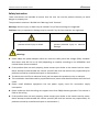
Safety Instruction
These instructions are intended to ensure that the user can use the product correctly to avoid
danger or property loss.
The precaution measure is divided into ‘Warnings’ and ‘Cautions’:
Warnings: Serious injury or death may be caused if any of these warnings are neglected.
Cautions: Injury or equipment damage may be caused if any of these cautions are neglected.
Warnings Follow these safeguards to
prevent serious injury or death.
Cautions Follow these precautions to
prevent potential injury or material
damage.
Warnings:
Please adopt the power adapter which can meet the safety extra low voltage (SELV) standard.
And source with DC 12V or AC 24V (depending on models) according to the IEC60950-1 and
Limited Power Source standard.
If the product does not work properly, please contact your dealer or the nearest service center.
Never attempt to disassemble the camera yourself. (We shall not assume any responsibility for
problems caused by unauthorized repair or maintenance.)
To reduce the risk of fire or electrical shock, do not expose this product to rain or moisture.
This installation should be made by a qualified service person and should conform to all the local
codes.
Please install blackouts equipment into the power supply circuit for convenient supply
interruption.
Please make sure that the ceiling can support more than 50(N) Newton gravities if the camera is
fixed to the ceiling.
If the product does not work properly, please contact your dealer or the nearest service center.
Never attempt to disassemble the camera yourself. (We shall not assume any responsibility for
problems caused by unauthorized repair or maintenance.)

Installation Manual of Network Camera
4
Notice:
Make sure the power supply voltage is correct before using the camera.
Do not drop the camera or subject it to physical shock.
Do not touch sensor modules with fingers. If cleaning is necessary, use a clean cloth with a bit
of ethanol and wipe it gently. If the camera will not be used for an extended period of time, put
on the lens cap to protect the sensor from dirt.
Do not aim the camera lens at the strong light such as sun or incandescent lamp. The strong
light can cause fatal damage to the camera.
The sensor may be burned out by a laser beam, so when any laser equipment is being used,
make sure that the surface of the sensor not be exposed to the laser beam.
Do not place the camera in extremely hot, cold temperatures (the operating temperature
should be between -10°C ~ 60°C ), dusty or damp environment, and do not expose it to high
electromagnetic radiation.
To avoid heat accumulation, good ventilation is required for a proper operating environment.
Keep out of water and any liquid.
While shipping, the camera should be packed in its original packing.
Improper use or replacement of the battery may result in hazard of explosion. Please use the
manufacturer recommended battery type.

Installation Manual of Network Camera
5
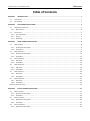
Table of Contents
CHAPTER 1 INTRODUCTION .................................................................................................................................... 1
1.1 APPLICATIONS .......................................................................................................................................................... 1
1.2 PREPARATIONS .......................................................................................................................................................... 1
CHAPTER 2 BOX CAMERA INSTALLATION ................................................................................................................. 2
2.1 APPEARANCE DESCRIPTION ......................................................................................................................................... 2
2.1.1 Box Camera I .................................................................................................................................................... 2
2.2 INSTALLATION ........................................................................................................................................................... 4
2.2.2 Lens Installation ............................................................................................................................................... 4
2.2.3 Wiring .............................................................................................................................................................. 4
2.2.4 Mounting ......................................................................................................................................................... 5
CHAPTER 3 DOME CAMERA INSTALLATION ............................................................................................................. 8
3.1 DOME CAMERA I ...................................................................................................................................................... 8
3.1.1 Appearance Description ................................................................................................................................... 8
3.1.2 Installation ....................................................................................................................................................... 9
3.2 DOME CAMERA II ................................................................................................................................................... 14
3.2.3 Appearance Description ................................................................................................................................. 14
3.2.4 Installation ..................................................................................................................................................... 15
3.3 DOME CAMERA III .................................................................................................................................................. 29
3.3.1 Overview ........................................................................................................................................................ 29
3.3.2 Installation ..................................................................................................................................................... 31
3.4 DOME CAMERA IV .................................................................................................................................................. 34
3.4.3 Overview ........................................................................................................................................................ 35
3.4.4 Installation ..................................................................................................................................................... 35
3.5 DOME CAMERA V ................................................................................................................................................... 38
3.5.5 Overview ........................................................................................................................................................ 38
3.5.6 Installation ..................................................................................................................................................... 39
3.6 DOME CAMERA VI .................................................................................................................................................. 42
3.6.7 Overview ........................................................................................................................................................ 42
3.6.8 Installation ..................................................................................................................................................... 43
IMAGE AND FOCUS ADJUSTING ............................................................................................................................................... 54
CHAPTER 4 BULLET CAMERA INSTALLATION ........................................................................................................... 57
4.1 BULLET CAMERA I ................................................................................................................................................... 57
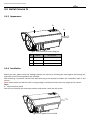
4.1.1 Appearance Description ................................................................................................................................. 57
4.1.2 Installation ..................................................................................................................................................... 58
4.2 BULLET CAMERA II .................................................................................................................................................. 60
4.2.1 Appearance Description ................................................................................................................................. 60
4.2.2 Installation ..................................................................................................................................................... 61
4.3 BULLET CAMERA III ................................................................................................................................................. 63
4.3.3 Appearance Description ................................................................................................................................. 63

Installation Manual of Network Camera
6
4.3.4 Installation ..................................................................................................................................................... 63
4.4 BULLET CAMERA IV ................................................................................................................................................. 65
4.4.5 Appearance .................................................................................................................................................... 65
4.4.6 Installation ..................................................................................................................................................... 65
4.5 BULLET CAMERA V .................................................................................................................................................. 67
4.5.1 Appearance .................................................................................................................................................... 67
4.5.2 Installation ..................................................................................................................................................... 68
CHAPTER 5 CUBE CAMERA INSTALLATION .............................................................................................................. 75
5.1 CUBE CAMERA I ...................................................................................................................................................... 76
5.1.1 Appearance Description ................................................................................................................................. 76
5.1.2 Installation ..................................................................................................................................................... 77
5.2 CUBE CAMERA II ..................................................................................................................................................... 79
5.2.3 Appearance Description ................................................................................................................................. 79
5.2.4 Installation ..................................................................................................................................................... 80
CHAPTER 6 MINI DOME CAMERA INSTALLATION ................................................................................................... 84
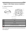
6.1 APPEARANCE DESCRIPTION ....................................................................................................................................... 84
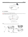
6.2 INSTALLATION ......................................................................................................................................................... 85

Installation Manual of Network Camera
1
Chapter 1 Introduction
The network camera is a kind of embedded digital surveillance product that combines the features
of both traditional analog camera and net DVS (Digital Video Server). With a built-in video server,
the network camera is capable of providing real-time video stream compression, processing, video
analysis and transmission simultaneously. Applying the latest processing chip and hardware
platform, the network camera can be widely applied to various surveillance and image processing
systems with high reliability and stability.
1.1 Applications
This camera can be adopted for network video surveillance systems, e.g.:
Network surveillance for over-the-counter activities in the banks, ATMs, supermarkets and
factories.
Remote surveillance systems for nursing homes, kindergartens and schools.
Artificial Intelligent access control systems .
Artificial Intelligent office building/residential compounds management systems.
Unguarded power station and telecommunication base station surveillance systems.
Pipelining and warehousing monitoring systems.
Surveillance systems for airports, railway stations, bus stops, etc.
1.2 Preparations
Before you start:
Verify the package contents are correct by checking the items against the packing list.
Read the following contents carefully before installation.
Make sure that all the related equipment is power-off during installation.
Check whether the power supply is matched with your AC outlet to avoid damage.
Do not place the camera in extremely hot or damp environment. To avoid heat
accumulation, good ventilation of the operating environment is required.
If the product does not function properly, please contact your dealer or the nearest service
center. Do not disassemble the camera for repair or maintenance by yourself.

Installation Manual of Network Camera
2
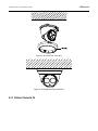
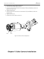
Chapter 2 Box Camera Installation
2.1 Appearance Description
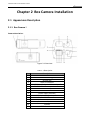
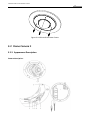
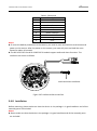
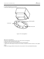
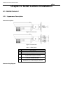
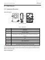
2.1.1 Box Camera I
Camera description:
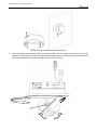
Figure 2-1 Overview
Table 2-1 Description
No.
Description
1
Lens mount
2
Back focus ring
3
SD card slot
4
Auto-iris interface
5
10M/100M self-adaptive Ethernet interface
6
VIDEO OUT: Video output interface
7
AUDIO OUT: Audio output interface
8
POWER: Power LED indicator
9
Power supply interface
10
MIC IN: Audio input interface
11
D+, D-: RS-485 interface
12
IN, G: Alarm input interface
13
1A, 1B: Alarm output interface
14
Ground
15
RESET: Reset button

Installation Manual of Network Camera
3
Notes:
To reset the default parameters to the camera, you need to press and hold the RESET
button and power on the camera. After the power on of the camera, you must still press and
hold the Reset button for about 20 seconds.
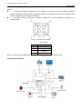
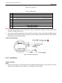
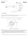
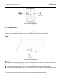
The type of auto-iris interface is shown in Figure 2-2, and the definition of each pin is
shown below:
Figure 2-2 Auto-iris Interface
Table 2-2 Pins
DC-driven
1
Damp-
2
Damp+
3
Drive+
4
Drive-
Damp+, Damp-, Drive+ and Drive- pins are used when the auto-iris is driven by DC.
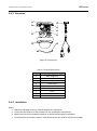
Camera wiring Diagram:

Installation Manual of Network Camera
4
Figure 2-3 Wiring Diagram
2.2 Installation
Box camera I, II, III can be installed to wall or ceiling. Ceiling mounting is taken as an example in this
section; if you adopt wall mounting, you can also take the below procedure as a reference.
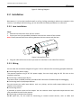
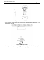
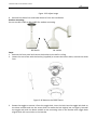
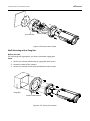
2.2.2 Lens Installation
Steps:
1. Remove the back cover from the lens mount.
2. Screw your lens (not provided) clockwise onto the lens mount of the camera.
Note: Please prevent dust from entering between the lens mount and the lens.
Figure 2-4 Install the Lens
3. Plug the cable of the lens to the 4-pin auto-iris interface on the side of the camera.
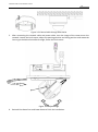
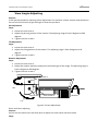
2.2.3 Wiring
You can take the connection diagram of Figure 2-3 as a reference for connecting peripheral devices:
Connecting the power supply
The cameras operate using a DC 12V power supply. You can simply plug the DC 12V wire to the
supplied connector.
Connecting a video output device
The camera with no HDMI interface provides a BNC connector of video output for debugging.
Connecting audio input/output devices
You can connect an audio input device, such as a pickup, and an audio output device such as a
speaker to the camera.
Connecting alarms
It provides an alarm input and an output. You can connect alarm input and output devices with
relay controlled circuits to the camera.
Connecting a remote control device
RS-485 ports (D+, D-) are used for connecting to remote control devices, such as DVRs and

Installation Manual of Network Camera
5
keyboards.
Grounding
The ground screw can be connected for grounding.
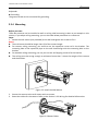
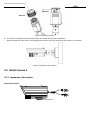
2.2.4 Mounting
Before you start:
These box cameras can be installed to wall or ceiling. Wall mounting is taken as an example in this
section; if you adopt ceiling mounting, you can also take below procedure as a reference.
Steps:
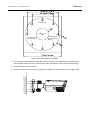
1. Attach the wall mount (not provided) to the wall and tighten the screws to fix it.
Notes:
The wall mount should be longer than 1/2 of the camera length.
For cement ceiling mounting, you need to use the expansion screw to fix the bracket. The
mounting hole of the expansion pipe on the wall should align with the mounting hole on the
bracket.
For wooden ceiling mounting, you can just use the self-tapping screw to fix the bracket.
The ceiling must be strong enough to withstand more than 3 times the weight of the camera
and the bracket.
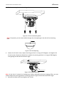
Figure 2-5 Install the Wall Mount
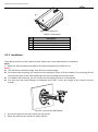
2. Secure the camera to the wall mount with set screws.
3. Route the cables for the camera. Refer to the Section 2.2.3 Wiring for detailed information.
Figure 2-6 Route Cables

Installation Manual of Network Camera
6
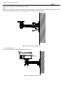
Figure 2-7 Mount the Camera
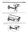
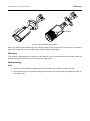
Note: This camera is designed for indoor and outdoor use. To use the camera outdoors, it must be
installed in an approved outdoor housing as shown in Figure 2-8.
Figure 2-8 Wall Mounting with the Housing
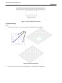
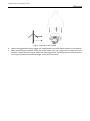
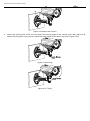
4. Loosen the panning lock screw, you can adjust the panning angle of the camera up to 360°
(Figure 2-9); Loosen the tilting lock screw, you can adjust the tilting angle of the camera up to
90° (Figure 2-10).
Figure 2-9 Panning

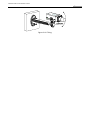
Installation Manual of Network Camera
7
Figure 2-10 Tilting

Installation Manual of Network Camera
8
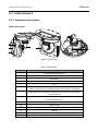
Chapter 3 Dome Camera Installation
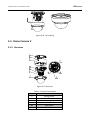
3.1 Dome Camera I
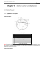
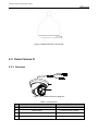
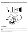
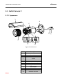
3.1.1 Appearance Description
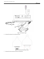
Camera description:
Figure 3-1 Overview
Table 3-1 Description
No.
Description
1
10M/100M self-adaptive Ethernet interface
2
INITIAL SET: Reset button
3
AUDIO OUT: Audio output interface
4
MIC IN: Audio input interface
5
D+, D-: RS-485 interface
6
1A, 1B, 2A, 2B: Alarm output interface
7
IN1, GND, IN2, GND: Alarm input interface
8
Power supply interface
Note: To reset the default parameters to the camera, you need to press and hold the RESET button
and power on the camera. After the power on of the camera, you must still press and hold the
Reset button for about 20 seconds
Camera wiring Diagram:

Installation Manual of Network Camera
9
Figure 3-2 Wiring Diagram
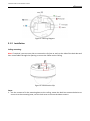
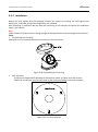
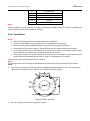
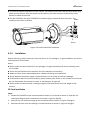
3.1.2 Installation
Ceiling mounting:
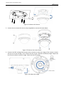
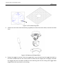
Note: If required, you can use a plier to remove the clip (one or two) on the side of the back box and
then route cables through the opening to secure the cables on the ceiling.
Figure 3-3 Remove the Clip
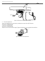
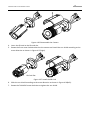
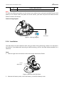
Steps:
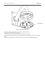
1. Use the screws to fix the mounting base to the ceiling; rotate the back box counterclockwise to
secure it to the mounting base; use the lock screw to secure the dome camera.

Installation Manual of Network Camera
10
Figure 3-4 Mount the Camera
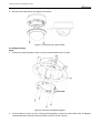
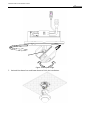
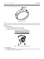
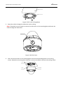
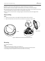
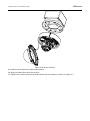
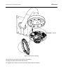
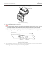
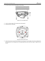
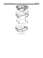
2. Loosen the set screws with the hex key (supplied) to remove the lower dome.
Figure 3-5 Remove the Lower Dome
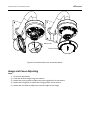
3. Connect the RCA analog video output with a monitor to view the image of the camera. Loosen
the lens set screw and pan, tilt or rotate the lens to get a desired surveillance angle. Adjust the
lens focus to obtain a perfect image. Fasten the lens set screw.
Figure 3-6 Adjust the image

Installation Manual of Network Camera
11
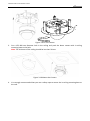
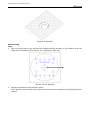
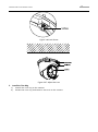
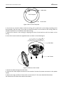
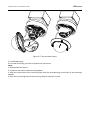
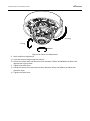
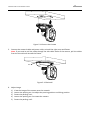
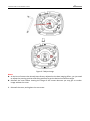
4. Reinstall the lower dome and tighten the screws.
Figure 3-7 Reinstall the Lower Dome
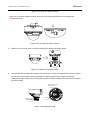
In-ceiling mounting:
Steps:
1. Secure the mounting base to the in-ceiling mounting base with screws.
Figure 3-8 Secure the Mounting Base
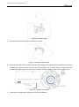
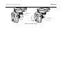
2. Push the dome camera to the in-ceiling mounting base, rotate the dome camera for 10 degrees
counterclockwise and then fasten the lock screws to fix the camera.

Installation Manual of Network Camera
12
Figure 3-9 Fix the Camera
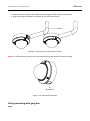
3. Cut a 176~180 mm diameter hole in the ceiling and push the dome camera with in-ceiling
mounting base to the hole.
Note: The thickness of the ceiling should be less than 30 mm.
Figure 3-10 Mount the Camera
4. It is strongly recommended that you use a safety rope to secure the in-ceiling mounting base to
the roof.

Installation Manual of Network Camera
13
Figure 3-11 Safety rope
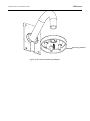
5. Fasten the lock screws to secure the dome camera.
Figure 3-12 Secure the Camera
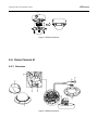
6. Remove the lower dome and connect the RCA analog video output with a monitor to view the
image of the camera. Loosen the lens set screw and pan, tilt or rotate the lens to get a desired
surveillance angle. Adjust the lens focus to obtain a perfect image. Fasten the lens set screw.
Figure 3-13 Adjust the Image
7. Install the trim plate with screws to finish the installation.
Page is loading ...
Page is loading ...
Page is loading ...
Page is loading ...
Page is loading ...
Page is loading ...
Page is loading ...
Page is loading ...
Page is loading ...
Page is loading ...
Page is loading ...
Page is loading ...
Page is loading ...
Page is loading ...
Page is loading ...
Page is loading ...
Page is loading ...
Page is loading ...
Page is loading ...
Page is loading ...
Page is loading ...
Page is loading ...
Page is loading ...
Page is loading ...
Page is loading ...
Page is loading ...
Page is loading ...
Page is loading ...
Page is loading ...
Page is loading ...
Page is loading ...
Page is loading ...
Page is loading ...
Page is loading ...
Page is loading ...
Page is loading ...
Page is loading ...
Page is loading ...
Page is loading ...
Page is loading ...
Page is loading ...
Page is loading ...
Page is loading ...
Page is loading ...
Page is loading ...
Page is loading ...
Page is loading ...
Page is loading ...
Page is loading ...
Page is loading ...
Page is loading ...
Page is loading ...
Page is loading ...
Page is loading ...
Page is loading ...
Page is loading ...
Page is loading ...
Page is loading ...
Page is loading ...
Page is loading ...
Page is loading ...
Page is loading ...
Page is loading ...
Page is loading ...
Page is loading ...
Page is loading ...
Page is loading ...
Page is loading ...
Page is loading ...
Page is loading ...
Page is loading ...
Page is loading ...
Page is loading ...
Page is loading ...
Page is loading ...
-
 1
1
-
 2
2
-
 3
3
-
 4
4
-
 5
5
-
 6
6
-
 7
7
-
 8
8
-
 9
9
-
 10
10
-
 11
11
-
 12
12
-
 13
13
-
 14
14
-
 15
15
-
 16
16
-
 17
17
-
 18
18
-
 19
19
-
 20
20
-
 21
21
-
 22
22
-
 23
23
-
 24
24
-
 25
25
-
 26
26
-
 27
27
-
 28
28
-
 29
29
-
 30
30
-
 31
31
-
 32
32
-
 33
33
-
 34
34
-
 35
35
-
 36
36
-
 37
37
-
 38
38
-
 39
39
-
 40
40
-
 41
41
-
 42
42
-
 43
43
-
 44
44
-
 45
45
-
 46
46
-
 47
47
-
 48
48
-
 49
49
-
 50
50
-
 51
51
-
 52
52
-
 53
53
-
 54
54
-
 55
55
-
 56
56
-
 57
57
-
 58
58
-
 59
59
-
 60
60
-
 61
61
-
 62
62
-
 63
63
-
 64
64
-
 65
65
-
 66
66
-
 67
67
-
 68
68
-
 69
69
-
 70
70
-
 71
71
-
 72
72
-
 73
73
-
 74
74
-
 75
75
-
 76
76
-
 77
77
-
 78
78
-
 79
79
-
 80
80
-
 81
81
-
 82
82
-
 83
83
-
 84
84
-
 85
85
-
 86
86
-
 87
87
-
 88
88
-
 89
89
-
 90
90
-
 91
91
-
 92
92
-
 93
93
-
 94
94
-
 95
95


Hikvision DS-2CD 7264FWD-EIZHS Installation guide
- Category
- Security cameras
- Type
- Installation guide
Ask a question and I''ll find the answer in the document
Finding information in a document is now easier with AI
Related papers
-
Hikvision Digital Technology DS-2CD4232FWD-H User manual
-
Hikvision DS-2CE5512PN-IR User manual
-
Hikvision DS-2CD2232-I5 User manual
-
Hikvision DS-2CD4324F-IZHS User manual
-
Hikvision DS-2CC52A1P User manual
-
Hikvision Digital Technology DS-2CD4112FWD User manual
-
Hikvision DS-2CD4132F-Z Installation guide
-
Hikvision DS-KH6320-WTE1-W(O-STD) Owner's manual
-
-
Hikvision DS-2DF6231-CX(T5/316L) Quick start guide
Other documents
-
AEI AAX-4100 User guide
-
PACOM PPRO-DA-MA2100 Technical Manual
-
Vitek VT-1230A-D18 User manual
-
-
 IDIS DA-SS1100 Technical Manual
-
Voyager VCMS36L/R Installation guide
-
ElectrIQ CDW12L-BKT Owner's manual
-
-
AVer PTMLTWA01 Installation guide
-
 ANKO 43243969 User manual

