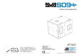
dBTechnologies DVA S10DP User manual
- Category
- Loudspeakers
- Type
- User manual
This manual is also suitable for

A.E.B. INDUSTRIALE s.r.l.
Via Brodolini, 8 - 40056 Crespellano (Bo) - ITALIA
Tel. + 39 051 969870 - Fax. + 39 051 969725
Internet: www.dbtechnologies.com
E-mail: [email protected]
Made in Italy
COD. 420120164 Rev. 5
digital power
RR
SS
00
ACTIVE SUBWOOFER
MANUALE d’USO - Sezione 1
USER MANUAL - Section 1
BEDIENUNGSANLEITUNG - Abschnitt 1
CARACTERISTIQUES TECHNIQUES - Section 1
Page is loading ...

3
EnglishEnglishEnglish
user manualuser manual
EnglishEnglishEnglish
user manualuser manual
4
CONTROLS AND FUNCTIONS
1) "MAINS FUSE" FUSE CARRIER
Mains fuse housing.
2) “FULL RANGE MAINS INPUT" POWER SOCKET
For connecting the power cable provided.
The connector used for mains connection is a POWER CON® (blue)
3) “LINK” RELAUNCH POWER SOCKET
For relaunching the mains power. The output is connected in parallel with input (2)
and can be used to power another amplified speaker.
The connector uses a POWER CON® (grey)
4) COOLING GRILLE
These grilles permit cooling the amplifier during operation.
Do not block accesses and clean the grilles whenever necessary to ensure correct
air circulation.
5) " BALANCED MAIN INPUT” INPUT CONNECTOR
Balanced input at line level (0 dBu).
It is able to accept “XLR” sockets.
6) "LINK” OUTPUT CONNECTOR
The “XLR” connector connected in parallel with input (5) can be used to send the
input audio signal to another amplified speaker.
7) ”BALANCED X-OVER OUTPUT” OUTPUT CONNECTOR
Internal crossover balanced output. The signal from this output can be sent to any
other amplified speaker.
The crossover frequency can be selected by means of the “SUB X-OVER” switch (8).
8) “SUB X-OVER” SWITCH
This switch permits selection of crossover frequency between the sub woofer and
the speakers connected to the ”BALANCED X-OVER OUTPUT” connector.
The crossing frequency is selected to 90Hz or 120Hz with a slope of 24dB/oct.
The frequency choice depends to the sound reproduction desire.
9) “SUB PHASE ” SWITCH
This switch permits 180° rotation of the audio signal reproduced by subwoofer.
Rotation makes for easier optimization of low-frequency reproduction even in the
most difficult installation situations. After completing installation, reproduce a piece
of music and adjust the switch to obtain the best low-frequency sound.
10) “ON” INDICATOR LIGHT
The “ON” indicator light comes on green to indicate the amplifier is switched on and it
is working properly.
11) “SGN” INDICATOR LIGHT
This indicator comes on green to indicate the presence of the audio signal (at a level
of -20dB).
12) “LIM” INDICATOR LIGHT
This indicator comes on red to indicate that the internal limiter circuit has tripped.
This prevents amplifier distortion and protects the speakers against overloads.
It is lights for a few seconds during the switching on.
13) “SUB WOOFER LEVEL” INPUT SENSITIVITY CONTROL
This control regulates the sensitivity of the signal at amplifier input.
This control does not affect the “LINK” and “BALANCED X-OVER OUTPUT” output
levels
14) DIGITAL DELAY “SDD - SUBWOOFER DIGITAL DELAY” OPTION
The DVA S10dp loudspeaker can be equipped with a delay module (SDD -
SUBWOOFER DIGITAL DELAY) that allows to delay the sound signal reproduced
by the subwoofer. This circuit allows sound-alignment between line array and sub
by balancing the various positions.
The circuit also includes a balanced “XLR” output that sends the delayed audio
TECHNICAL SPECIFICATION
System Active
Type of amplifier Digital - Class D (DIGIPRO )
RMS power 1000 W
Musical power 2000 W
Frequency responce +/-3dB 40-150Hz
Crossover 90 - 120Hz (24dB/oct) selecting
Sound pressure (SPL) 136dB peak
Woofer 1 x woofer 18” - 4” voice coil
Neodymium or Ceramic
Input sensitivity nominal 0 dBu
Impedance input Balanced 20Kohm
Unbalanced 10Kohm
Speaker shape rectangular
Dimension [WxHxD] 515x640x770mm
Weight Neodymium 42Kg - Ceramic 48Kg
Weight Neodymium 47,2Kg - Ceramic 53,2kg
®
Full-range with PFC, 100-240Vac, 50-60Hz
(with SRK10 Fly kit)
Power supply
signal to other subwoofers. By using a single delay module it is possible to delay
several subwoofers at the same time.
This module can also be used to create cardioid configuration systems. The cardioid
configuration provides a remarkable attenuation of the low frequencies radiated by
the rear side of the subs, without changing the direct radiated signal on the fronside.
This configuration needs at least 3 subwoofers (two with front radiation and one with
rear radiation equipped with SDD module). See appendix for more details.
EMI CLASSIFICATION
According to the standards EN 55103 this equipment is designed and suitable to operate in E3
(or lower E2, E1) Electromagnetic environments.
220-240V~ MAX 15A
100-120V~ MAX 10A
BALANCED
MAIN INPUT
LINK
BALANCED
X-OVER
OUTPUT
+10
+4
SUB-WOOFER
LEVEL
90Hz
120Hz
0°
180°
ON SGN
LIM
SUB
PHASE
SUB
XOVER
FULL RANGE MAINS INPUT
100-240V~ 50-60Hz
1250W MAX
MAINS FUSE
220-240V~ ( T5A 250V )
100-120V~ (T10A 250V)
ACTIVE P.F.C.
Made in Italy
SERIAL N.
“CAUTION”
TO PREVENT ELECTRICAL SHOCK
DO NOT REMOVE COVER
“AVIS”
RISQUE DE CHOCH ELECTRIQUE
NE PAS OUVRIR
LINK
BB
dd
TECHNOLOGIESTECHNOLOGIES
digital powerdigital powerdigital powerdigital power
1
2
3
1 = GND
2 = HOT
3 = COLD
12
3
1
2
3
SS
00
digital powerdigital powerdigital powerdigital powerdigital power
8
0dB
PUSH
SUBWOOFER DIGITAL DELAY
DD
B
d
TECHNOLOGIESTECHNOLOGIES
SS
OPTIONAL CARD
DD
ON
5
6
7
9
11
13
12
10
8
4
1
2
3
4
4
4
14
NEODYMIUM CERAMIC
Page is loading ...
Page is loading ...
Page is loading ...

11
12
INSTALLATION
DVA system has obtained the TÜV certification for suspension of DVA T4 and DVA
S10dp speakers through flybar stirrup DRK 10.
The report certifies that the maximum weight applying to DRK 10 flybar is 250Kg.
DVA T4 configuration
The DRK 10 flybar attests that the maximum number of DVA T4 is 16.
Refer to table 1 to determine the total weight borne by flybar according to the different
DVA T4 configurations.
Table 1 Quantity Weight
DVA T4 [kg] [lbs.]
1 15 33
2 30 66
3 45 99
4 60 132
5 75 165
6 90 198
7 105 231
8 120 264
9 135 297
10 150 330
11 165 363
12 180 396
13 195 429
14 210 462
15 225 495
16 240 528
DVA S10dp configuration
The DRK 10 flybar attests that the maximum number of DVA S10dp with Neodymium
woofer is 4 and DVA S10dp with Ceramic woofer is 5.
Refer to table 2 to determine the total weight borne by flybar according to the different
DVA S10dp configurations.
Structural modification of DRK 10 flybar
No structural modifications may be made without the manufacturer's consent.
Use only dB Technologies original parts
Original parts dB Technologies
Use only dB Technologies original parts.
The TÜV authorizing body has not certificated any other parts for use!
Always install parts in accordance with these installation instruction!
Compile and store all DVA system documents in a safe place!
Warning
If the security norms and total weight calculations are not observed, dB Technologies
is not responsible for any possible damage to people and things.
Note
During installation ensure that carrying structure of the system has added in the total
weight also the DRK 10 flybar weight, chain hoists, motors, cables and further weights.
Initiation and Operation
The safety regulation “§ 39, VBG 9a” of the German employers' liability insurance
association's accident prevention regulations requires that load-carrying equipment be
inspected by a qualified expert and possible defects be eliminated prior to initial
commissioning by the recipient.
The safety regulation “§ 41, VBG 9a” requires that load-carrying equipment be subjected
to a non-routine inspection following damage, repair work and other incidents that can
affect load-carrying capacity.
Warning
The safety regulations might be different in other countries. Please check with your
national safety authority the valid regulations!
EnglishEnglishEnglish
EnglishEnglishEnglish
user manualuser manual
user manualuser manual
Quantity Weight x qty Configuration weight
DVA T4 12 180Kg
DVA S10dp (Neodymium woofer) 1 48Kg
228Kg
Quantity Weight x qty Configuration weight
DVA T4 8 120Kg
DVA S10dp (Neodimium woofer) 2 96Kg
216Kg
Mixed configuration with DV A T4 and DV A S10dp (Neodimium woofer)
The modular structure of DV A system permit s mixed suspension configuration between
DVA T4 and DVA S10dp. It is necessary to consider that one DVA S10dp hanging
subwoofer corresponds, in weight terms, to about four DVA T4 speakers.
For this reason it is necessary to calculate the total weight according to the different
configurations.
Examples:
Quantity Weight
DVA S10dp [kg] [lbs]
(Neodymium woofer)
1 48 106
2 96 212
3 144 317
4 192 423
5 240 528
Quantità Weight
DVA S10dp [kg] [lbs]
(Ceramic woofer)
1 54 119
2 108 238
3 162 357
4 216 476
Table 2
DVA Composer Acoustical Simulation and aiming for DVA Systems
DVA Composer is a 2D software for aiming and simulating acoustical response of all line
arrays and Subwoofers from DVA Series.
The software allows you to set up a stereo system composed by tops and subs, and
simulates separately the acoustical response of both.
DVA Composer also gives to the user all the information about phase alignment between
flown systems and ground stacked subwoofers, as well as it suggests an optimized
aiming of the line arrays modules and their suggested EQ presets, in order to guarantee
maximum performances even for non-expert customers.
It is recommended to download DVA_Composer free software directly from
dB Technologies (www.dbtechnologies.com) in the special section «
Software & Controller»
DOWNLOAD
Page is loading ...
Page is loading ...

17
18
BALANCED
INPUT
BALANCED
LINK / OUT
1 = GND
2 = HOT
3 = COLD
PUSH
Digital Vertical Array
T
4
MIXER
FULL RANGE
OUTPUT
BALANCED
INPUT
BALANCED
LINK / OUT
1 = GND
2 = HOT
3 = COLD
PUSH
Digital Vertical Array
T
4
BALANCED
INPUT
BALANCED
LINK / OUT
1 = GND
2 = HOT
3 = COLD
PUSH
Digital Vertical Array
T
4
BALANCED
INPUT
BALANCED
LINK / OUT
1 = GND
2 = HOT
3 = COLD
PUSH
Digital Vertical Array
T
4
COLLEGAMENTI
CABLE CONNECTIONS
VERKABELUNG
CABLAGE
SCHEMA A BLOCCHI
BLOCK DIAGRAM
BLOCKSCHALTBILD
DIAGRAMA EM BLOQURES
BALANCED
MAIN INPUT
LINK
BALANCED
X-OVER
OUTPUT
90Hz
120Hz
SUB
X-OVER
switch
Digital Delay
Optional
WOOFER 18”
LIMITER
SUB
PHASE
switch
Phase
180°
Phase
0°
SIGNAL
-20dB
CONTROL CIRCUITS
L
N
MAINS INPUT
MAINS
FUSE
INPUT
SENS
READY
L
N
MAINS INPUT
LINK
BALANCED
MAIN INPUT
LINK
BALANCED
X-OVER
OUTPUT
1
2
3
1 = GND
2 = HOT
3 = COLD
12
3
1
2
3
S
0
PUSH
Switching Mode
Power Supply
PFC
Power Factor
Correction
SMPS
Class D
®
DIGIPRO
Class D

19
20
INSTALLAZIONE
INSTALLATION
INSTALLATIONEN
INSTALLATIONS
In appoggio - impilato
Groundstack - stacked
In appoggio
Groundstack
In appoggio con flybar (opzione DRK 10)
Groundstack with flybar (DRK 10 option)

22
21
Appeso con kit staffe (opzione SRK-10) e flybar (opzione DRK-10)
Hang with stirrups kit (SRK-10 option) and flybar (DRK-10 option)
Kit staffe- opzione SRK 10
Kit stirrups - SRK-10 option
In appoggio con kit staffe
Groundstack with kit stirrups

23
24
In appoggio son supporto su asta
per Groundstack with stand adaptor
Set di 4 ruote - opzione DWK 20
Set of 4 wheels - DWK 20 option
In appoggio a pavimento con supporto asta provvisto di piedi
Groundstack to floor with stand adaptor with feet
Per supporto asta
Stand adaptor
Opzione DSA 4
DSA 4 Option
In appoggio
Floor stack

25
Digital Delay subwoofer - opzione SDD
Subwoofer Digital Delay - SDD option
GAP
mSec
DELAY SET-UP
.0
.5
.4
.3
.1
.2
.6
.7
.8
.9
0
5
4
3
1
2
6
7
8
9
0
50
40
30
10
20
60
70
80
90
- - -
.
ALLINEAMENTO SEGNALE AUDIO
ALIGNAMENT AUDIO SIGNAL
CONFIGURAZIONE CARDIOIDE
CARDIOID CONFIGURATION
26
Delay setup = (GAP X 1000) / 344
Delay = ms (specify milliseconds)
GAP = m (specify meters)
Sound speed = 344 m/s
Ruotare la fase di 180°
Rotate 180° phase
SUB
PHASE
0°
180°
Impostare il delay a 4,5msec
Set delay to 4,5msec
mSec
DELAY SET-UP
.0
.5
.4
.3
.1
.2
.6
.7
.8
.9
0
5
4
3
1
2
6
7
8
9
0
50
40
30
10
20
60
70
80
90
- - -
.
Delay = ms (espresso in millisecondi)
GAP = m (espresso in metri)
Velocità suono = 344 m/s
BALANCED
MAIN INPUT
LINK
BALANCED
X-OVER
OUTPUT
+10
+4
SUB-WOOFER
LEVEL
90Hz
120Hz
0°
180°
ON SGN
LIM
SUB
PHASE
SUB
XOVER
BB
dd
TECHNOLOGIESTECHNOLOGIES
1
2
3
1 = GND
2 = HOT
3 = COLD
12
3
1
2
3
SS
00
8
0dB
PUSH
BALANCED
MAIN INPUT
LINK
BALANCED
X-OVER
OUTPUT
+10
+4
SUB-WOOFER
LEVEL
90Hz
120Hz
0°
180°
ON SGN
LIM
SUB
PHASE
SUB
XOVER
B
d
TECHNOLOGIES
1
2
3
1 = GND
2 = HOT
3 = COLD
12
3
1
2
3
SS
00
8
0dB
PUSH
PUSH
NEODYMIUM CERAMIC
-
 1
1
-
 2
2
-
 3
3
-
 4
4
-
 5
5
-
 6
6
-
 7
7
-
 8
8
-
 9
9
-
 10
10
-
 11
11
-
 12
12
-
 13
13
-
 14
14
dBTechnologies DVA S10DP User manual
- Category
- Loudspeakers
- Type
- User manual
- This manual is also suitable for
Ask a question and I''ll find the answer in the document
Finding information in a document is now easier with AI
in other languages
- italiano: dBTechnologies DVA S10DP Manuale utente
- français: dBTechnologies DVA S10DP Manuel utilisateur
- Deutsch: dBTechnologies DVA S10DP Benutzerhandbuch
Related papers
-
 AEB DVA T8 User manual
-
dBTechnologies DVA K5 Owner's manual
-
dBTechnologies Composer Owner's manual
-
dBTechnologies SUB 15D Owner's manual
-
 AEB DVA S09DP User manual
-
A.E.B. DVA S08DP User manual
-
dBTechnologies Network Owner's manual
-
dBTechnologies DVA Mini G2 Owner's manual
-
dBTechnologies KL 15 Owner's manual
-
dBTechnologies VIO S218F Owner's manual
Other documents
-
 Triton Systems SDD Owner's manual
-
OSD Audio BLACK TREVOCE 12 Owner's manual
-
 T'nB CB01 Datasheet
-
dB Technologies DVA K5 Quick start guide
-
dB Technologies SUB 618 Quick start guide
-
Stinger SRK-JW18EH User guide
-
dB Technologies DVA KS10 Quick start guide
-
dB Technologies DVA KS20 Quick start guide
-
Omnitronic XO-23 User manual
-
Stinger SGN111 Owner's manual


