Page is loading ...

High Performance 6 GHz
Pulse Burst Radar
Level Transmitter
S
A
F
E
T
Y
I
N
T
E
G
R
I
T
Y
L
E
V
E
L
2014/68/EU
Software Version 1.x

BE 58-602 Pulsar
®
Model R96 Radar Transmitter
Read this Manual Before Installing
This manual provides information on the Pulsar
®
Model
R96 Radar transmitter. It is important that all instruc-
tions are read carefully and followed in sequence. The
QuickStart Installation instructions are a brief guide to the
sequence of steps for experienced technicians to follow
when installing the equipment. Detailed instructions are
included in the Complete Installation section of this manual.
Conventions Used in this Manual
Certain conventions are used in this manual to convey
specific types of information. General technical material,
support data, and safety information are presented in nar-
rative form. The following styles are used for notes, cau-
tions, and warnings.
NOTES
Notes contain information that augments or clarifies
an operating step. Notes do not normally contain
actions. They follow the procedural steps to which
they refer.
Cautions alert the technician to special conditions that
could injure personnel, damage equipment, or reduce
a component’s mechanical integrity. Cautions are also
used to alert the technician to unsafe practices or the
need for special protective equipment or specific mate-
rials. In this manual, a caution box indicates a poten-
tially hazardous situation which, if not avoided, may
result in minor or moderate injury.
Warnings identify potentially dangerous situations or
serious hazards. In this manual, a warning indicates an
imminently hazardous situation which, if not avoided,
could result in serious injury or death.
Safety Messages
The PULSAR Model R96 system is designed for use in
Category II, Pollution Degree 2 installations. Follow all
standard industry procedures for servicing electrical and
computer equipment when working with or around high
voltage. Always shut off the power supply before touching
any components. Although high voltage is not present in
this system, it may be present in other systems.
Electrical components are sensitive to electrostatic dis-
charge. To prevent equipment damage, observe safety
procedures when working with electrostatic sensitive
components.
This device complies with Part 15 of the FCC rules.
Operation is subject to the following two conditions:
(1) This device may not cause harmful interference, and
(2) This device must accept any interference received,
including interference that may cause undesired operation.
FCC ID: LPN R96
Any unauthorized changes or modifications not expressly
approved by the party responsible for compliance could
void user’s authority to operate this equipment.
Explosion hazard. Do not connect or dis-
connect designs rated Explosion-proof or Non-incendive
unless power has been switched off and/or the area is
known to be non-hazardous.
Low Voltage Directive
For use in Installations Category II, Pollution Degree 2.
If equipment is used in a manner not specified by the
manufacturer, protection provided by equipment may be
impaired.
Notice of Copyright and Limitations
Magnetrol
®
& Magnetrol
®
logotype and Pulsar
®
are registered trademarks of Magnetrol
®
International,
Incorporated.
Copyright © 2020 Magnetrol
®
International,
Incorporated. All rights reserved.
MAGNETROL reserves the right to make changes to the
product described in this manual at any time without
notice. MAGNETROL makes no warranty with respect
to the accuracy of the information in this manual.
Warranty
All MAGNETROL electronic level and flow controls are
warranted free of defects in materials or workmanship for
one full year from the date of original factory shipment.
If returned within the warranty period; and, upon facto-
ry inspection of the control, the cause of the claim is
determined to be covered under the warranty; then,
MAGNETROL will repair or replace the control at no cost
to the purchaser (or owner) other than transportation.
MAGNETROL shall not be liable for misapplication,
labor claims, direct or consequential damage or expense
arising from the installation or use of equipment. There
are no other warranties expressed or implied, except spe-
cial written warranties covering some MAGNETROL
products.
Quality Assurance
The quality assurance system in place at MAGNETROL
guarantees the highest level of quality throughout the
company. MAGNETROL is committed to providing
full customer satisfaction both in quality products and
quality service.
The MAGNETROL quality assurance system is registe-
red to ISO 9001 affirming its commitment to known
international quality standards providing the strongest
assurance of product/service quality available.

BE 58-602 Pulsar
®
Model R96 Radar Transmitter
1.0 QuickStart Installation
1.1 Getting Started..........................................................5
1.1.1 Equipment and Tools .....................................5
1.1.2 Configuration Information.............................6
1.2 QuickStart Mounting................................................7
1.2.1 Antenna .........................................................7
1.2.2 Transmitter.....................................................7
1.3 QuickStart Wiring ....................................................8
1.4 QuickStart Configuration .........................................8
1.4.1 QuickStart Menu Options ...........................10
1.4.1.1 QuickStart Numerical Data Entry...........11
2.0 Complete Installation
2.1 Unpacking ..............................................................12
2.2 Electronic Discharge (ESD) Handling Procedure....12
2.3 Before You Begin.....................................................13
2.3.1 Site Preparation ............................................13
2.3.2 Equipment and Tools ...................................13
2.3.3 Operational Considerations..........................13
2.3.3.1 Maximum Distance...............................14
2.3.3.2 Minimum Distance...............................14
2.3.3.3 Problematic Applications;
GWR Alternative ..................................14
2.4 Mounting................................................................15
2.4.1 Installing the Antenna ..................................15
2.4.1.1 Location................................................15
2.4.1.2 Beam Angle...........................................15
2.4.1.3 Obstructions .........................................16
2.4.1.4 Nozzles..................................................16
2.4.1.5 Standpipes and Stillwells .......................17
2.4.2 Installing the Transmitter .............................17
2.4.2.1 Orientation ...........................................17
2.4.2.2 Initial Installation..................................18
2.4.2.3 Low Echo Margin .................................18
2.5 Wiring ....................................................................19
2.5.1 General Purpose or Non-Incendive ..............19
2.5.2 Intrinsically Safe...........................................20
2.5.3 Explosion Proof............................................20
2.6 Configuring the Transmitter....................................21
2.6.1 Bench Configuration....................................21
2.6.2 Menu Traversal and Data Entry....................22
2.6.2.1 Navigating the Menu ............................22
2.6.2.2 Data Selection.......................................22
2.6.2.3 Entering Numeric Data Using
Digit Entry ...........................................23
2.6.2.4 Entering Numeric Data Using
Increment/Decrement ...........................23
2.6.2.5 Entering Character Data .......................24
2.6.3 Password Protection .....................................24
2.6.4 Menu: Step-By-Step Procedure.....................25
2.6.5 Configuration Menu: Device Setup..............28
2.7 Configuration Using HART
®
..................................33
2.7.1 Connections .................................................33
2.7.2 Display Menu...............................................33
2.7.3 HART Revision Table ..................................33
2.7.3.1 Model R96............................................33
2.7.4 HART Menu................................................34
3.0 Reference Information
3.1 Description .............................................................36
3.2 Theory of Operation...............................................36
3.2.1 Pulse Burst Radar .........................................36
3.2.2 Equivalent Time Sampling ...........................37
3.3 Configuration Information .....................................37
3.3.1 Bottom Blocking Distance Description ........37
3.3.2 Echo Rejection .............................................39
3.3.3 Volumetric Capability ..................................39
3.3.3.1 Configuration Using Built-in
Vessel Types...........................................39
3.3.3.2 Configuration Using Custom Table ......41
3.3.4 Reset Function...............................................41
3.4 Troubleshooting and Diagnostics ............................42
3.4.1 Diagnostics (Namur NE 107) ......................42
3.4.2 Diagnostic Indication Simulation.................44
3.4.3 Diagnostic Help ...........................................44
3.4.4 Diagnostic Indicator Table ...........................46
3.4.5 Additional Diagnostic/Trouble
Shooting Capabilities ...................................48
3.4.5.1 Echo History Setup...............................48
3.4.5.2 Event History........................................48
3.4.5.3 Context-sensitive Help..........................48
3.4.5.2 Trend Data............................................48
continued on next page
Table of Contents
Pulsar
®
Model R96
Pulse Burst Radar Level Transmitter

BE 58-602 Pulsar
®
Model R96 Radar Transmitter
3.5 Agency Approvals....................................................49
3.5.1 Agency Drawing & Entity Parameters..........50
3.6 Parts........................................................................52
3.6.1 Replacement Parts ........................................52
3.7 Specifications ..........................................................53
3.7.1 Functional – Transmitter..............................53
3.7.2 Functional – Environmental.........................54
3.7.2.1 Safe Operating Area..............................55
3.7.2.2 Supply Voltage ......................................55
3.7.3 O-ring (seal) Selection Chart........................55
3.7.4 Functional – Antenna...................................56
3.7.5 PULSAR Model R96 Antenna
Pressure/Temperature Rings .........................56
3.7.6 Physical ........................................................57
3.8 Model Numbers......................................................58
3.8.1 PULSAR Model R96 Radar Transmitter ......58
3.8.2 Radar Antennas – Dielectric Rod .................59
3.8.3 Radar Antennas – Horn ...............................60
4.0 Advanced Configuration/Troubleshooting Techniques
4.1 Echo Rejection.........................................................61

BE 58-602 Pulsar
®
Model R96 Radar Transmitter
1.0 QuickStart Installation
The QuickStart Installation procedures provide an overview
of the key steps for mounting, wiring, and configuring the
PULSAR Model R96 radar level transmitter. These proce-
dures are intended for experienced installers of electronic
level measurement instruments.
See Complete Installation, Section 2.0, for detailed installa-
tion instructions.
1.1 Getting Started
Before beginning the QuickStart Installation procedures,
have the right equipment, tools, and information available.
No special tools are needed. The following items are
recommended:
• Threaded antenna and process connection . . . . 2" (50 mm)
• Transmitter/antenna connection . . 1 3/4" (44 mm) wrench
• Transmitter adjustment . . . . . . . . . 1 1/8" (28 mm) wrench
. . . . . . . . . . . . . . . . . . . . . . . . . . . . . . 3/32" Hex wrench
• Torque wrench . . . . . . . . . . . . . . . . . . . . . . highly desirable
• Flat-blade screwdriver
• Digital multimeter or volt/ammeter . . . . . . . . . . . Optional
• 24 VDC (23 mA) power supply . . . . . . . . . . . . . . Optional

BE 58-602 Pulsar
®
Model R96 Radar Transmitter
To utilize the QuickStart menu available on the
PULSAR Model R96, some key information is required
for configuration.
Gather the information and complete the following operating
parameters table before beginning configuration.
NOTES: The QuickStart menu is available for Level Only applications.
1. Refer to Section 2.6.5 for configuration menus for Volume
applications.
2. These configuration steps are not necessary if the transmitter
was pre-configured prior to shipment.
Level What units of measurement will be
Units used? _____________
Tank What is the tank height? _____________
Height
Antenna What type of antenna is being used?
Model Select first 7 digits of Model number.
(See nameplate on side of antenna) _____________
Antenna What is maximum nozzle length for
Extension which the antenna can be used?
Select last 3 digits of Model number.
(See nameplate on side of antenna) _____________
Antenna Is the antenna mounting NPT, BSP,
Mount or flanged? _____________
Dielectric What is the dielectric of the process
medium? _____________
4 mA What is the 0% reference point for the
Setpoint 4.0 mA value? _____________
(LRV)
20 mA What is the 100% reference point for
Setpoint the 20.0 mA value? _____________
(URV)
PV Alarm What output current is desired when a
Selection failure indicator is present? _____________

BE 58-602 Pulsar
®
Model R96 Radar Transmitter
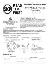
1.2 QuickStart Mounting
NOTE: Confirm the configuration style and process connection (size
and type) of the PULSAR Model R96 radar transmitter. Ensure it
matches the requirements of the installation before continuing
with the QuickStart installation.
➀ Confirm the model and serial numbers on the nameplates
of PULSAR Model R96 electronics and antenna are identical.
➁ Carefully place the antenna into the vessel. Mount in a
location equal to 1/2 the radius of tank top. Do not mount
in center of vessel nor closer than 45 cm (18") of tank wall.
➂ Secure the antenna to the vessel.
➃ Leave the protective plastic cap in place until ready to
install the transmitter.
NOTE: Do not use sealing compound or TFE tape on antenna connec-
tion to transmitter. This connection is sealed by a Viton
®
O-ring.
1. Remove the protective plastic cap from the top of the
antenna and store for future use. Make sure the bottom of
the Universal connector (Teflon
®
) ➄ and inside of the
antenna are clean and dry. Clean with isopropyl alcohol and
cotton swabs if necessary.
2. Place the transmitter on the antenna.
3. Ensure the housing/launcher set screw is loose and the
housing can be turned. Align the antenna index mark so it
is at an angle of 45° to a line from the radar unit to the
nearest tank wall.
4. Rotate the transmitter so that it is in the most convenient
position for wiring, configuring, and viewing.
5. While keeping the housing and launcher aligned, tighten
both the housing/launcher set screw and large Universal
connector Hex nut. Tighten the universal connector to
40 Nm (30 ft./lbs) of force. A torque wrench is highly
desirable.
DO NOT LEAVE HAND TIGHT.
• Do not place insulating material around any part of the
Radar transmitter including the antenna flange.
➁
➀
➂
➃
➀
➄
Set Screw
Universal
Connector
Index Mark
1 dot: GP/IS
2 dots: XP

BE 58-602 Pulsar
®
Model R96 Radar Transmitter
1.3 QuickStart Wiring
Explosion hazard. Do not remove covers unless power
has been switched off or the area is known to be non-
hazardous.
NOTE: Ensure that the electrical wiring to the PULSAR Model R96
radar transmitter is complete and in compliance with all regula-
tions and codes.
1. Remove the cover of the upper wiring compartment.
2. Attach a conduit fitting and mount the conduit plug in the
spare opening. Pull the power supply wire through the con-
duit fitting.
3. If present, connect cable shield to an earth ground at the
power supply.
4. Connect the positive supply wire to the (+) terminal and the
negative supply wire to the (-) terminal. For Explosion
Proof Installations, see Wiring, Section 2.5.3.
5. Replace the cover and tighten.
1.4 QuickStart Configuration
If requested, the PULSAR Model R96 transmitter is
shipped fully pre-configured for the application and can be
installed immediately. Otherwise it is shipped configured
with default values from the factory and can be easily
reconfigured in the shop. The minimum configuration
instructions follow. Use the information from the operating
parameters table before beginning configuration. See
Configuration Information, Section 1.1.2.
The Quick Start menu offers a very simple two screen
overview showing the basic parameters required for a typical
“Level Only” application.
1. Apply power to the transmitter.
The graphic LCD display can be programmed to change
every 2 seconds to show pertinent Measured Values on the
Home Screen. For example: Level, %Output, and Loop
current can all be displayed on a rotating screen.
The LCD can also be programmed to always show just one
of the Measured Variables at all times. For example: Level
can be the only value displayed on the screen.
2. Remove the cover of the electronics compartment.
Up Down Back Enter
Black (-) Red (+)
(+)
(-)

BE 58-602 Pulsar
®
Model R96 Radar Transmitter
3. The push buttons offer multiple forms of functionality for
menu navigation and data entry. (See Section 2.6 for com-
plete explanation.)
UP moves up through the menu or increases a displayed
value.
DOWN moves down through the menu or decreases a
displayed value.
BACK exits a branch of the menu or exits without
accepting entered value.
ENTER enters a branch of the menu or accepts a
displayed entry.
NOTE: Holding down ENTER when any menu or parameter is high-
lighted will show help text in reference to that item.
The default User Password = 0. (If a password is requested,
enter it at that time.)
The following configuration entries are the minimum
required for a QuickStart configuration. Refer to figures at
left.
4. Press any key at the Home Screen to access the Main Menu.
5. Press ENTER with the DEVICE SETUP menu item
highlighted.
6. Press ENTER with the QUICKSTART menu item
highlighted.
The QuickStart shows the basic parameters, with the
present value of the highlighted parameter shown at the
bottom of the screen.
One can now quickly and easily scroll through the
QuickStart configuration items, changing those parameters
as required:
• Scroll to the parameter to be changed.
• Press ENTER at the highlighted parameter.
• Scroll to the desired option, then press ENTER.
• Scroll to next parameter or press BACK when
finished to exit the QuickStart menu.
Section 1.4.1 lists and describes the nine parameters in the
QuickStart menu.
7. After making all of the necessary changes in the QuickStart
menu, press the BACK button three times to return to the
Home Screen.
8. The QuickStart configuration is complete. If properly con-
figured, the Model R96 transmitter is measuring level and is
ready for service.
➪
➪
➪
➪
➪
➪
➪
➪
➪
Up Down Back Enter

BE 58-602 Pulsar
®
Model R96 Radar Transmitter
Select the Units of measurement for the level readout:
• Inches • Feet • Millimeters • Centimeters • Meters
Enter tank height (in Level Units selected)
Select the Antenna Model to be used with Model R96 (refer to antenna nameplate):
• RAA-x — TFE rod
• RAB-G — Polypropylene rod
• RAB-L — Polypropylene rod
• RAB-x — Polypropylene rod
• RAC-x — Halar rod
• RA3-x — 3" horn
• RA4-x — 4" horn
• RA6-x — 6" horn
0 For nozzle height ≤ 25 mm (1") (for threaded process connection only) (refer to antenna
nameplate):
1 For nozzle height ≤ 100 mm (4")
2 For nozzle height ≤ 200 mm (8")
3 For nozzle height ≤ 300 mm (12")
Select the type of Antenna Mounting to the vessel (refer to antenna nameplate):
• NPT (National Pipe Thread)
• BSP (British Standard Pipe)
• Flange (ASME or EN)
Enter the Dielectric Range for the material to be measured.
Below 1.7 (Light Hydrocarbons like Propane and Butane) — (stillwell only)
1.7 to 3.0 (Most typical hydrocarbons)
3.0 to 10 (Varying dielectric, for example: mixing tanks)
Above 10 (Water-based media)
Enter the level value (0 %-point) for the 4 mA point. Lower Range Value (LRV).
Refer to Section 1.4.1.1.
Enter the level value (100 %-point) for the 20 mA point. Upper Range Value (URV).
Refer to Section 1.4.1.1.
Enter the desired output state when a Failure Indicator is active.
• High (22 mA)
• Low (3.6 mA)
• Hold (Hold last value is not recommended for standard configuration). Consult factory for
use.

BE 58-602 Pulsar
®
Model R96 Radar Transmitter
1.4.1.1 QuickStart Numerical Data Entry
To make numerical entry changes to Tank Height:
UP moves up to the next highest digit (0, 1, 2, 3,....,9
or the decimal point).
If held down the digits scroll until the push button is
released.
DOWN moves up to the next lowest digit (0, 1, 2, 3,...., 9
or the decimal point). If held down the digits scroll until
the push button is released.
BACK moves the cursor to the left and deletes a digit.
If the cursor is already at the leftmost position, then the
screen is exited without changing the previously saved
value.
ENTER Moves the cursor to the right. If the cursor is
located at a blank character position, the new value is
saved.
Scrolling further DOWN in the QuickStart menu results in
the remaining parameters appearing one by one, with the
present highlighted value shown at the bottom of the
screen.
BACK returns to the previous menu without changing
the original value, which is immediately redisplayed.
ENTER accepts the displayed value and returns to the
previous menu.
➪
➪
➪
➪
➪
➪
Sensor Reference Point
Measurement
Region
Tank
Height
20 mA
4 mA

BE 58-602 Pulsar
®
Model R96 Radar Transmitter
2.0 Complete Installation
This section provides detailed procedures for properly
installing, wiring, configuring, and, as needed, troubleshoot-
ing the PULSAR Model R96 Radar Level Transmitter.
2.1 Unpacking
Unpack the instrument carefully. Make sure all components
have been removed from the packing material. Check all the
contents against the packing slip and report any discrepancies
to the factory.
Before proceeding with the installation, do the following:
• Inspect all components for damage. Report any damage to
the carrier within 24 hours.
• Make sure the nameplate model number on the antenna and
transmitter agree with the packing slip and purchase order.
• To avoid moisture ingress in the housing, covers should be
fully tightened at all times. For the same reason, plugs
should remain properly installed in the cable entries until
replaced with a cable gland
• Record the model and serial numbers for future reference
when ordering parts.
2.2 Electrostatic Discharge (ESD)
Handling Procedure
MAGNETROL electronic instruments are manufactured to
the highest quality standards. These instruments use electronic
components that may be damaged by static electricity present
in most work environments.
The following steps are recommended to reduce the risk of
component failure due to electrostatic discharge.
• Ship and store circuit boards in anti-static bags. If an anti-
static bag is not available, wrap the board in aluminum foil.
Do not place boards on foam packing materials.
• Use a grounding wrist strap when installing and removing
circuit boards. A grounded workstation is recommended.
• Handle circuit boards only by the edges. Do not touch
components or connector pins.
• Make sure that all electrical connections are completely
made and none are partial or floating. Ground all equip-
ment to a good, earth ground
Potential electrostatic charging hazard. Do not rub
with dry cloth.
Model Number
Serial Number

BE 58-602 Pulsar
®
Model R96 Radar Transmitter
2.3 Before You Begin
Each PULSAR Model R96 Radar transmitter/antenna is
built to match the physical specifications of the required
installation. Ensure that the probe process connection is
correct for the threaded or flanged mounting on the vessel
where the transmitter will be placed. See Mounting,
Section 2.4.
Ensure that all local, state, and federal regulations and
guidelines are observed. See Wiring, Section 2.5.
Ensure that the wiring between the power supply and
PULSAR Model R96 Radar transmitter is complete and
correct for the type of installation. See Specifications,
Section 3.7.
No special tools are needed. The following items are
recommended:
• Threaded antenna and process connection . . . . 2" (50 mm)
• Transmitter/antenna connection . . 1 3/4" (44 mm) wrench
• Transmitter adjustment . . . . . . . . . 1 1/8" (28 mm) wrench
. . . . . . . . . . . . . . . . . . . . . . . . . . . . . . 3/32" Hex wrench
• Torque wrench . . . . . . . . . . . . . . . . . . . . . . highly desirable
• Flat-blade screwdriver
• Digital multimeter or volt/ammeter . . . . . . . . . . . Optional
• 24 VDC (23 mA) power supply . . . . . . . . . . . . . . Optional
Radar applications are characterized by three basic conditions;
Dielectric (process medium), Distance (measuring range)
and Disturbances (turbulence, foam, false targets, multiple
reflections and rate of change). The PULSAR Model R96
Radar transmitter is offered with two antenna configura-
tions—Horn and Dielectric Rod. Ideally, the 6" Horn
antenna should be used to ensure the best possible perform-
ance in all operational conditions.
2.3.3.1 Maximum Distance
The chart on the following page shows the maximum meas-
uring range (Distance) of each antenna based on fundamental
conditions of Dielectric, Distance and Turbulence. Distance
is measured from the Sensor Reference Point (bottom of
NPT thread, top of BSP thread or face of a flange).

BE 58-602 Pulsar
®
Model R96 Radar Transmitter
2.3.3.2 Minimum Distance
If the liquid level is allowed onto the antenna, noise and
media build-up drastically decrease reliable measurement.
Liquid should not be allowed closer than 50 mm (2") from
the bottom of the antenna.
2.3.3.3 Problematic Applications; GWR Alternative
Some application concerns can be problematic for Non-
Contact Radar. For these, Guided Wave Radar is recom-
mended:
• Extremely low dielectric media (
ε
r
<1.7)
• Stillwells, standpipes, bridles, cages and bypass columns.
• Very weak reflections from the liquid surface (particularly
during turbulence) can cause poor performance.
• Tanks heavily cluttered with false targets (mixers, pumps,
ladders, pipes, etc.)
• During times of very low liquid levels of low dielectric media,
the metal tank bottom may be detected which can deterio-
rate performance.
• Foam can either absorb or reflect the microwave energy
depending upon the depth, dielectric, density and wall
thickness of the bubbles. Due to typical variations in the
amount (depth) of foam, it is impossible to quantify per-
formance. It may be possible to receive most, some or none
of the transmitted energy.
• When measurement close to flange is critical
Extremely high liquid levels (Overflow) conditions when
liquid very near the antenna can cause erroneous read-
ings and measurement failure.
Refer to ECLIPSE Model 706 bulletin BE 57-106 for
additional information.
1.7 - 3 3 - 10 10 - 100 1.7 - 3 3 - 10 10 - 100
Dielectric Rod
5 (16) 12 (39) 20 (66)
3 (10) 9 (29)
12 (39)
4" Horn
6" Horn 10 (33) 25 (82) 40 (131)
5 (16) 12 (39)
16 (52)

BE 58-602 Pulsar
®
Model R96 Radar Transmitter
2.4 Mounting
The PULSAR Model R96 Radar transmitter can be mount-
ed to a vessel using a variety of process connections.
Generally, either a threaded or flanged connection is used.
For information about the sizes and types of connections
available, see Antenna Model Numbers, Section 3.8.2.
Before installing, ensure that:
• Model and Serial numbers on the nameplates of the
PULSAR Model R96 transmitter and antenna are identical.
• Process temperature, pressure, dielectric, turbulence and
distance are within the antenna specifications for the
installation.
• Rod of a Dielectric Rod antenna is protected from bending
or breaking; there is no metal sub-structure.
• Insulating material is not placed around any part of the
Radar transmitter including the antenna flange.
• Protective cap is kept on the antenna if the transmitter is to
be installed at a later time.
• Antenna is being mounted in the optimal location. See fol-
lowing sections: Location, Beam Angle, Obstructions and
Nozzles for specific information.
• If the liquid level is allowed onto the antenna, noise and
media buildup drastically decrease reliable measurement.
Liquid should not be allowed closer than 50 mm (2") from
the bottom of the antenna.
2.4.1.1 Location
Ideally, the Radar transmitter should be mounted providing
an unobstructed signal path to the liquid surface where it
should illuminate (with microwave energy) the largest,
possible surface area. See Section 2.4.1.2, Beam Angle.
Unavoidable obstacles will produce reflections that must be
minimized during field configuration. See Section 3.3.2,
Echo Rejection. Mount in a location equal to 1/2 the radius
of tank top. Do not mount in center of vessel nor closer
than 45 cm (18") of tank wall.
2.4.1.2 Beam Angle
The various antenna designs exhibit different beam patterns.
Ideally, the beam pattern should illuminate with microwave
beam the maximum liquid surface with minimum contact
with other objects in the vessel including the tank wall. Use the
drawings at left to determine the optimum installation location.
D
W
W
∝ ∝
Antenna
Beam Angle
(
∝
)
Beam Spread, W @-3dB; m (ft)
Dielectric
Rod
25°
4" Horn
25°
6" Horn
17°
Distance, D
3 (10) 1,4 (4.5) 1,0 (3.0)
6 (20) 2,7 (8.9) 1,8 (6.0)
9 (30) 4,11 (3.3) 2,7 (9.0)
12 (40) 5,4 (17.8) 3,7 (12.0)
15 (50) 6,8 (22.2) 4,6 (15.0)
18 (60) 8,1 (26.6) 5,5 (18.0)
20 (65) 8,8 (28.9) 6,0 (19.5)
30 (98) * 9,0 (29.3)
40 (130) * 12,0 (39.0)
*Dielectric rod and 4" horn not recommended beyond 20 m (65 ft).

BE 58-602 Pulsar
®
Model R96 Radar Transmitter
2.4.1.3 Obstructions
Almost any object that falls within the beam pattern will cause
reflections that may be misinterpreted as a false liquid level.
Although PULSAR Model R96 has a powerful Echo
Rejection routine, all possible precautions should be taken to
minimize false target reflections with proper installation and
orientation. Refer to section 2.4.2.3 for additional information.
2.4.1.4 Nozzles
Improper installation in a nozzle creates “ringing” that will
adversely affect measurement. The antenna should always be
mounted so the active section of the antenna is a minimum
of 0.5" (13 mm) outside the nozzle. Antenna extensions are
offered to allow the PULSAR Model R96 transmitter to
work reliably in nozzles with “L” dimensions of 25 mm
(1"), 100 mm (4"), 200 mm (8") or 300 mm (12").
Standard antennas (no extension) are shown below for refer-
ence. See Section 3.7.6 for dimensional drawings of all
antenna designs including nozzle extensions.
C
D
∅
A
B
H
58 (2.3) 282 (11.1) 76 (3.0)
160 (6.3) 389 (15.3) 185 (7.3)
267 (10.5) 493 (19.4) 287 (11.3)
368 (14.5) 594 (23.4) 389 (15.3)
∅ 38 (1.50)
∅ 38 (1.50)
117 (4.6)
213 (8.4) 211 (8.3)
315 (12.4) 315 (12.4)
95 (3.75) 146 (5.75)

BE 58-602 Pulsar
®
Model R96 Radar Transmitter
2.4.1.5 Standpipes and Stillwells
The PULSAR Model R96 can be mounted in a standpipe
or stillwell but certain items must be considered:
• Metal stillwells only: Sizes 100–200 mm (4–8"). (Beyond
200 mm (8"), effects are negligible.)
• Diameter must be consistent throughout length; no reducers.
• Use only horn antennas sized to pipe inside diameter (ID);
100–150 mm (4–6"); 200 mm (8") pipe can use a 6" horn.
• Stillwell length must cover complete range of measurement
(i.e., liquid must be in stillwell).
• Welds should be smooth.
• Vents: holes < 13 mm (0.5") diameter, slots < 13 mm (0.5")
width.
• If an isolation valve is used, it must be a full port ball valve
with an I.D. equal to the pipe diameter.
• Bridles/Bypass Installations: The launcher (index mark)
should be rotated 90° from process connections.
• Configuration must include an entry for the STILWELL I.D
parameter. See Section 2.6.5.
• There will be some increased dielectric sensitivity; system
gain will be reduced when STILWELL ID > 0.
• Remove the protective plastic cap from the top of antenna.
Store the cap in a safe place in case the transmitter has to be
removed later.
• Carefully place the transmitter on the antenna.
• Rotate the transmitter to face the most convenient direction
for wiring, configuration and viewing. Do not tighten the
universal connector (large hex nut) nor the set screw on the
housing base. The transmitter launcher must be oriented
properly for optimal performance.
• Do not place insulating material around any part of the
radar transmitter including the antenna flange.
2.4.2.1 Orientation
The PULSAR Model R96 transmitter utilizes a linearly
polarized, microwave beam that can be rotated to improve
its performance. Proper orientation can minimize unwanted
target reflections, decrease sidewall reflections (multipath)
and maximize direct reflections from the liquid surface. The
index mark located on the side of the launcher is oriented in
the same direction as the polarization.
The index mark is also present for reference(1 dot: GP/IS or
2 dots: XP). The launcher is considered to be at 0° when
the index mark is closest to the tank wall. (See figures at left.)
45°
Set Screw
Universal
Connector
Index Mark
1 dot: GP/IS
2 dots: XP
Index
Mark
index mark

BE 58-602 Pulsar
®
Model R96 Radar Transmitter
2.4.2.2 Initial Installation
Ideally, the transmitter should be mounted half the radius
from the tank wall. Align the index mark so it is at an angle
of 45 degrees to a line from the radar unit to the nearest
tank wall. For horizontal cylindrical vessels, align the
launcher (index mark) so it is facing along the long axis of
the vessel. Once properly oriented, tighten set screws and
Universal connector (40 Nm (30 ft-lbs) of force).
A transmitter mounted within 45 cm (18") of a tank wall may
demand orientation adjustments to limit multipath and
optimize performance. See Section 2.4.2.3 Low Echo Margin.
NOTE: ALWAYS RUN THE ECHO REJECTION ROUTINE AFTER MAKING
CHANGES TO MENU CHOICES ( ,
,
) or when launcher is
repositioned.
2.4.2.3 Low Echo Margin
Low Echo Margin has many potential causes. Following are
two initial areas for investigation.
Launcher Orientation: Initial launcher orientation is always
45 degrees (see Sections 2.4.1 & 2.4.2). In tall vessels and
when antenna is mounted close to the tank wall, improve-
ment in Echo Margin (signal quality) may be attained by
rotating the launcher to 90 degrees.
Echo Loss: If the Level signal is lost repeatedly at a specific
point in the vessel, it is usually a symptom that multipath
(side-wall) reflections are causing cancellation by returning
to the transmitter exactly 180° out of phase with the actual
Level signal. This can be improved by utilizing the follow-
ing procedure:
• Scroll to Display Config Menu under Device Setup. This
menu shows both Level and Echo Margin.
• Bring the Level up (or down) to the exact point where the
signal is repeatedly lost. Monitor the Echo Margin value as
this point is being approached. The Echo Margin value will
degrade to a low point before it begins to increase.
• When the Echo Margin reaches this low point, loosen both
the Universal connector and the set screw. Slowly rotate the
launcher clockwise approximately 10–20° (the transmitter
can be rotated independently). Allow the unit to stabilize
for approximately 1 minute. Repeat this process until the
Echo Margin value is optimized.
• Without disturbing the position of the launcher, position
the transmitter head back to its most convenient location.
• Tighten both the Universal connector (40 Nm (30 ft-lbs) of
force) and Launcher set screw.
45°
90°
Launcher
Index mark
(facing 45°)
1/2 Radius
Set Screw
Universal
Connector

BE 58-602 Pulsar
®
Model R96 Radar Transmitter
NOTE: ALWAYS RUN THE TARGET REJECTION ROUTINE AFTER
MAKING CHANGES TO MENU CHOICES ( ,
) or
when launcher is repositioned.
2.5 Wiring
HART versions of the PULSAR Model R96 transmitter
operate at voltages of 11–36 VDC. FOUNDATION Fieldbus
™
versions operate at 9–17.5 VDC. Higher voltages will dam-
age the transmitter.
Wiring connections between the power supply and the
PULSAR Model R96 Radar Transmitter should be made
using 0.5
–1 mm
2
(18–22 AWG) shielded twisted pair
instrument cable. Connections are made to the terminal
strip and the ground connections within the top enclosure
compartment.
The directions for wiring the PULSAR Model R96 trans-
mitter depend on the application:
• General Purpose or Non-Incendive (Cl I, Div. 2)
• Intrinsically Safe
• Explosion Proof
Explosion hazard. Do not disconnect equipment unless
power has been switched off or the area is known to be
non-hazardous.
To avoid moisture ingress in the housing, covers should be
fully tightened at all times. For the same reason, cable
gland and plugs should be properly installed in the cable
entries.
A general purpose installation does not have flammable
media present.
Areas rated Non-Incendive (Cl I, Div. 2) have flammable
media present only under abnormal conditions.
No special electrical connections are required.
If flammable media is contained in the vessel, the trans-
mitter must be installed per Class I, Div 1 standards of
area classification.
To install General Purpose or Non-Incendive wiring:
1. Remove the cover from the wiring compartment of the
transmitter. Install the conduit plug in the unused opening
and use PTFE tape/sealant to ensure a liquid-tight
connection.
2. Install a conduit fitting and pull the supply wires.
3. Connect shield to an earth ground at power supply.
4. Connect an earth ground wire to the nearest green ground
screw (not shown in illustration).
Black (-) Red (+)
(+)
(-)

BE 58-602 Pulsar
®
Model R96 Radar Transmitter
5. Connect the positive supply wire to the (+) terminal and
the negative supply wire to the (-) terminal.
6. Replace and tighten the cover to the transmitter wiring
compartment before applying power.
An Intrinsically Safe (IS) installation potentially has flam-
mable media present. An approved IS barrier must be
installed in the non-hazardous (safe) area to limit the avail-
able energy out to the hazardous area.
See Agency Drawing – Intrinsically Safe Installation,
Section 3.5.1.
To install Intrinsically Safe wiring:
1. Ensure that the IS barrier is properly installed in the safe
area (refer to local plant or facility procedures). Complete
the wiring from the power supply to the barrier and from
the barrier to the PULSAR Model R96 transmitter.
2. Remove the cover from the wiring compartment of the
transmitter. Install the conduit plug in the unused opening
and use PTFE tape/sealant to ensure a liquid-tight
connection.
3. Install a conduit fitting and pull the supply wires.
4. Connect shield to an earth ground at power supply.
5. Connect an earth ground wire to the nearest green ground
screw (not shown in illustration).
6. Connect the positive supply wire to the (+) terminal and
the negative supply wire to the (-) terminal.
7. Replace and tighten the cover to the wiring compartment
of the transmitter before applying power.
Explosion Proof (also referred to as XP or flameproof) is
another method of designing equipment for installation
into hazardous areas. A hazardous location is an area in
which flammable gases or vapors are (or may be) present
in the air in quantities sufficient to produce explosive or
ignitable mixtures.
The wiring for the transmitter must be contained in
Explosion Proof conduit extending into the safe area.
• Due to the specialized design of the PULSAR Model R96
transmitter, no Explosion Proof conduit fitting (EY seal) is
required within 460 mm (18") of the transmitter.
• An Explosion Proof conduit fitting (EY seal) is required
between the hazardous and safe areas. See Agency
Specifications, Section 3.5.
Black (-) Red (+)
(+)
(-)
/