Page is loading ...

OWNER’S MANUAL
Composite Pressurized
Water Tanks
© 2012 CH20463 (02/17/12)
293 Wright Street, Delavan, WI 53115
PSC Series
Installation/Operation/Parts
For further operating, installation,
or maintenance assistance:
Call 1-262-728-9181
Tested and Certified by the WQA
to NSF/ANSI Std. 61 Section 8

READ AND FOLLOW
SAFETY INSTRUCTIONS!
This is the safety alert symbol. When you see this
symbol on your pump or in this manual, look for one of the
following signal words and be alert to the potential for
personal injury:
warns about hazards that will cause serious
personal injury, death or major property damage if ignored.
warns about hazards that can cause serious
personal injury, death or major property damage if ignored.
warns about hazards that will or can cause
minor personal injury or property damage if ignored.
The label NOTICE indicates special instructions which are
important but not related to hazards.
Carefully read and follow all safety instructions in this
manual and on pump.
Keep safety labels in good condition.
Replace missing or damaged safety labels.
RULES FOR SAFE
INSTALLATION AND OPERATION
NOTE: Installation must comply with all applicable state,
provincial, and local statutes, codes and ordinances. Non-
compliant installation may result in product failure, property
damage, and/or personal injury.
1. Read the Owner’s Manual and Rules for Safe Operation and
Installation Instructions carefully. Failure to follow these Rules
and Instructions could cause serious bodily injury and/or
property damage.
2. Always test water from well for purity before using. Check
your local health department for testing procedure.
3. Before installing or servicing your tank, BE SURE pump
electric power source is disconnected.
4. Release all pressure before working on tank or system.
Make sure all air pressure has been released before remov-
ing tank flanges.
5. BE SURE your pump electrical circuit is properly grounded.
6. Remove bleeder orifices, air volume controls or other air
charging devices in existing system.
Safety 2
Install in compliance with all applicable
laws, codes and ordinances. Non-com-
pliance may cause product failure, prop-
erty damage, and/or personal injury.
Install this tank in vertical position only.
If your installation requires a horizontal
tank, contact your dealer for available
steel tanks.
LIMITED WARRANTY
PENTAIR WATER warrants to the original consumer purchaser (“Purchaser” or “You”) of the products listed below, that they will be free from
defects in material and workmanship for the Warranty Period shown below.
Product Warranty Period
Water Systems Products –
whichever occurs first:
jet pumps, small centrifugal pumps, 12 months from date of original installation, or
submersible pumps and 18 months from date of manufacture
related accessories
PENTEK INTELLIDRIVE 12 months from date of original installation, or
18 months from date of manufacture
Pro-Source™ Composite Tanks 5 years from date of original installation
Pro-Source™ Steel Pressure Tanks 5 years from date of original installation
Pro-Source™ Epoxy-Line Tanks 3 years from date of original installation
Sump/Sewage/Effluent Products 12 months from date of original installation, or
18 months from date of manufacture
Our warranty will not apply to any product that, in our sole judgement, has been subject to negligence, misapplication, improper
installation, or improper maintenance. Without limiting the foregoing, operating a three phase motor with single phase power through a
phase converter will void the warranty. Note also that three phase motors must be protected by three-leg, ambient compensated, extra-
quick trip overload relays of the recommended size or the warranty is void.
Your only remedy, and PENTAIR WATER’s only duty, is that PENTAIR WATER repair or replace defective products (at PENTAIR WATER’s
choice). You must pay all labor and shipping charges associated with this warranty and must request warranty service through the
installing dealer as soon as a problem is discovered. No request for service will be accepted if received after the Warranty Period has
expired. This warranty is not transferable.
PENTAIR WATER SHALL NOT BE LIABLE FOR ANY CONSEQUENTIAL, INCIDENTAL, OR CONTINGENT DAMAGES WHATSOEVER.
THE FOREGOING WARRANTIES ARE EXCLUSIVE AND IN LIEU OF ALL OTHER EXPRESS AND IMPLIED WARRANTIES,
INCLUDING BUT NOT LIMITED TO THE IMPLIED WARRANTIES OF MERCHANTABILITY AND FITNESS FOR A PARTICULAR
PURPOSE. THE FOREGOING WARRANTIES SHALL NOT EXTEND BEYOND THE DURATION EXPRESSLY PROVIDED HEREIN.
Some states do not allow the exclusion or limitation of incidental or consequential damages or limitations on the duration of an implied
warranty, so the above limitations or exclusions may not apply to You. This warranty gives You specific legal rights and You may also have
other rights which vary from state to state.
This warranty supersedes and replaces all previous warranty publications.
PENTAIR WATER, 293 Wright St., Delavan, WI 53115

Safety 3
To prevent possible serious or fatal injury
and/or damage to equipment, system pressure must be
less than 125 pounds per square inch gauge (psig) under
any circumstances. Failure to follow this instruction can
result in tank explosion. If system discharge pressure
can exceed 125 psig, install a relief valve capable of pass-
ing the full pump volume at 125 psig. Install relief valve in
pump supply line to tank, as close to tank as possible.
Hazardous pressure. Read owner’s manual
before attempting to install, operate, or service this tank.
To avoid possible equipment failure, severe injury, and
property damage, do not allow pump, tank, or piping sys-
tem to freeze.
GENERAL SAFETY
All tanks are factory pre-charged with air. When installing
tank, adjust pre-charge to 2 psig below pump cut-in pressure
setting. To do this, bleed air from or add air to the valve on top
of the tank.
NOTICE: Always set pre-charge with NO WATER in tank.
Check pressure frequently with an accurate tire pressure
gauge until correct pressure has been reached. For correct
pre-charge pressure settings, see Chart 1, below.
CHART I
NOTICE: Replace and tighten air valve cap if it is removed for
any reason. Failure to replace air cap may allow loss of air
pressure and eventually lead to tank waterlogging and air cell
failure.
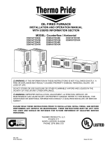
Pre-charged storage tanks can be connected together to
increase the supply of usable water (drawdown). Two tanks of
the same size will double the supply and three tanks will triple
the supply. See Figures No. 1A and 1B for typical installations
of this kind.
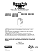
OPERATING CYCLE:
1. Tank nearly empty – air expands filling area inside
air cell (Figure 2A).
2. Water begins to enter tank – air is compressed in air
cell as tank fills with water (Figure 2B).
3. Pump-up cycle completed – air pressure has reached
the cut off setting of pressure switch (Figure 2C).
4. Water being drawn from tank – compressed air in air
cell forces water out of tank (Figure 2D).
5. Tank now empty – new cycle ready to begin
(Figure 2A).
Pressure Switch Setting Tank Precharge (psig)
20-40 psig 18
30-50 psig 28
40-60 psig 38
50-70 psig 48
From
Well
To
Service
Tanks
Pressure Switch
From
Well
To
Service
Tanks
Pressure Switch
Figure 1A:Typical Layout With Two Tanks
Figure 1B: Typical Layout With Three Tanks
Air Air
Water
Air
Air
Water
Figure 2A Figure 2B
Figure 2C Figure 2D
Figure 2:Air Cell Cycle

Operation / Installation 4
Chart II – Water Yield Per Pump Cycle
(drawdown) in Gallons
INSTALLATION
Connect system pipe to elbow on tank flange. Use plas-
tic or steel pipe as required. To prevent leaks, use
PTFE tape on male threads of all threaded connections
to tank.
NOTICE: To be sure that joint is not cross-threaded and
that threads are clean, always make connections by
hand (without sealer) first. After making sure that
threads are clean, remove pipe, add PTFE tape and
remake connection. Do not overtighten pipe connection
at tank. Thread connection on hand tight plus 3 addi-
tional turns for steel pipe and 1-2 turns for schedule 40
PVC pipe.
NOTICE: When replacing a standard tank in a sub-
mersible pump system, raise pump and discharge pipe
far enough to remove bleeder orifices from the tees in
the discharge pipe. Plug the tees. When replacing a
standard tank in a jet pump system, remove Air Volume
Control (AVC) and plug AVC port in pump.
In areas where the temperature is high for long periods
of time, the tank pre-charge pressure may increase.
This may reduce the tank drawdown (amount of water
available per cycle). If this occurs, reduce the pre-
charge pressure to two PSI below the pump cut-in set-
ting of the pressure switch.
It is necessary to flush all air out of the piping system
and water reservoir portion of the pre-charged tank.
This is required on new installations, pumps requiring
repriming and pumps that have been disassembled for
service. Proceed as follows:
1. Open faucets furthest from tank and allow pump to
operate.
2. Air in the system will cause a sputtering flow; allow
faucets to run until you have a steady, air free
stream.
3. Open and close faucets repeatedly until you are sure
all air has been removed.
4. If stream does not become steady, air may be leak-
ing into the system; check for leaks in the piping on
the suction side of the pump.
NOTICE: To prevent waterlogging, check tank air
charge every six months.
Tank
Model Capacity Pressure Switch Setting
Number (U.S. Gals) 20-40 30-50 40-60
PSC-14-4 14 5.3 4.5 3.9
PSC-20-6 20 7.2 6.1 5.3
PSC-30-9 30 10.8 9.1 7.9
PSC-35-10 35 12.8 10.8 9.4
PSC-40-12 40 14.7 12.5 10.8
PSC-48-14 48 17.2 14.6 12.6
PSC-60-20 60 21.9 18.5 16.1
PSC-80-23 80 29.1 24.6 21.3
PSC-85-25 85 31.7 26.8 23.2
PSC-119-35 119 43.8 37.0 32.0
Tank
Capacity Tank Tank Discharge
Model (U.S. Gals) Diameter Height Tapping
PSC-14-4 14 16” 31-5/16” 1”
PSC-20-6 20 16 36-5/16 1
PSC-30-9 30 16 48-5/16 1
PSC-35-10 35 21 37 1
PSC-40-12 40 16 61-5/16 1
PSC-48-14 48 21 44 1
PSC-60-20 60 24 46-9/16 1-1/4
PSC-80-23 802166 1
PSC-85-25 852458-9/16 1-1/4
PSC-119-35 119 24 78-9/16 1-1/4
NOTICE: Maximum Internal Water Temperature – 120° F.
Maximum Ambient Air Temperature – 120° F.
Distance from base to center line of connection is 2".
Allow 12" clearance over top of tanks for service access.
NOTICE: Drawdown will be affected by operating temperature
of the system, accuracy of the pressure switch and gauge,
the actual precharge pressure, and the rate of fill.
1
Lake Chemical Co., Chicago, Illinois
SPECIFICATIONS

Installation 5
TO CHECK TANK AIR CHARGE
If drawdown (amount of water that comes out of tank
per pump cycle) decreases significantly, check as
follows:
1. To check air charge in tank, shut off electric power to
pump, open faucet near tank, and drain completely.
2. Remove pole piece cap and check air pressure at
the air valve in top of tank with a standard tire
gauge. Air pressure should be 2 psig below pump
pressure switch cut-in setting (that is, if switch closes
at 30 psig, pressure in tank should be at 28 psig).
3. If the air pressure is more than 2 psig below the cut-
in setting, add air to the tank. Use an air compressor
or a portable air storage tank.
4. Use soap or liquid detergent to check for air leaks
around air valve. Continuous bubbling indicates a
leak. If necessary, install new core in air valve. This is
the same as those used for automobile tubeless tires.
TO CHECK PUMP PRESSURE
SWITCH SETTING
1. To check pressure switch setting, disconnect power
to pump at supply panel (but be sure to leave pres-
sure switch connected to power supply wires).
2. Remove pressure switch cover.
3. Open a faucet near tank.
4. Allow water to drain until pressure switch contacts
close; immediately close faucet.
5. Check pressure at valve with standard tire gauge or
with pump pressure gauge (if supplied).
6. Pressure gauge should read 2 psig below pump
cut-in setting (28 psig for 30-50 switch, 18 psig for
20-40 switch, etc.) If not:
A. Adjust switch according to switch manufacturer’s
instructions.
B. Reconnect power supply to pump and pump up
pressure in system.
C. Disconnect power supply to pump again and re-
check switch setting.
D. Repeat until pressure switch starts pump within
±1 psig of proper setting.
E. If cut-in setting is too low, system will rattle or
develop water hammer when pump starts.
F. Cut-out setting is not as critical as cut-in setting.
Make sure that pump will stop running in a rea-
sonable time. If it does not, cut-out setting may
need to be adjusted down slightly. Be sure that
after readjustment, system does not rattle or ham-
mer on startup.
7. Re-check tank air pre-charge to be sure it is 2 psig
below pump pressure switch cut-in setting.
TESTING FOR AIR CELL LEAKAGE
1. Disconnect power to pump.
2. Drain all water from tank by opening faucet closest
to tank.
3. Remove pole piece cap and valve cap from valve
and charge air cell.
4. Check air pressure after 24 hours. If air cell leaks,
pressure will drop. If so, replace air cell.
AIR CELL REPLACEMENT
To be sure polar boss cap cannot blow
off of tank, release all air from system before re-
moving capscrews from flange assembly.
1. Disconnect power to pump.
2. Follow steps 1 through 3 under “Testing For Air Cell
Leakage”.
3. Remove valve core (see Page 6).
4. Remove valve cap, hex nut and washer from valve.
5. With a screwdriver, pry the clips out and remove
them. Remove polar boss cap.
Figure 3: Use A Tire Gauge To Check Pre-charge In
Air Cell
5899 1008
Figure 4: Remove Pole Piece Cap,Valve Cap and
Retaining Nut, Clips, and Polar Boss Cap.

Installation 6
6. Air cell may not come out in one piece. Pull air cell
up with pliers and cut wherever convenient with sin-
gle edge razor blade or sharp knife. Continue pulling
and cutting until air cell is removed.
7. Before air cell can be inserted into tank, it must be
tightly rolled up as follows:
A. Remove valve core.
B. Place air cell on clean surface with opening to
one end; flatten bag to force air out. Pull ends out
flat (see Figure 5).
C. To get tightest possible wrap, start on one side
and TIGHTLY roll air cell to other side (see Figure
5). Force out as much air as possible.
8. Push and turn tightly rolled air cell into tank (see
Figure 6).
9. Shake air cell a few times inside tank to work wrin-
kles out. It is not necessary to remove all wrinkles
from cell.
NOTICE: Don’t push air cell into tank further than its
own length. In a large tank, air cell can slip out of
reach if pushed too far.
10. Clean tank sealing surface before installing top
flange assembly.
11. Clean sealing surface and groove of polar boss cap;
install O-ring and polar boss cap on tank.
12. Pull valve up through polar boss cap.
13. Install metal washer and nut on valve.
14. Reinstall polar boss cap into top opening. Fasten it
with two (2) red clips.
15. Recharge tank to proper air pressure and install
valve cap and install pole piece cap (see Page 5).
16. Prime pump (see pump owner’s manual).
VALVE CORE REPLACEMENT
To be sure air valve and core cannot
blow out of tank, release all air pressure from tank
before removing valve core.
1. Disconnect power to pump.
2. Drain ALL water in system by opening faucet clos-
est to tank.
3. Depress valve core to release ALL air pressure in
tank. When air stops coming out of valve, remove
core from inside of valve to release remaining pres-
sure. Thread new valve core into tank valve and
tighten.
NOTICE: Do not overtighten.
4. Recharge tank with air pressure (see Figure 3,
page 5) according to Chart I, Page 3; install valve
cap and pole piece cap; reconnect power to pump.
Tank is ready for service.
2
1
Figure 5: Spread Air Cell Out Flat and Squeeze Air Out;
Roll Cell Tightly, Squeezing Remaining Air Out Through
Valve
Figure 6:Turn and Push Air Cell Down Through Top Tank
Port. Expel Any Remaining Air From Air Cell As You Go

Installation 7
Pressure
Switch
To
Service
Relief
Valve
Floor
Drain
Pressure
Gauge
From
Submersible
Pump in Well
5896 1008
Figure 8:Typical Installation with Submersible Pump
Figure 9:Typical Installation with Vertical Multi-Stage
Pump
To
Service
Relief
Valve
Floor
Drain
Pressure
Gauge
20
100
8
60
40
Pressure
Switch
Pressure
Regulator
Check
Valve
Pressure
Switch
To Household
Water System
From W
e
ll
Relief Valve
Check Valve
5895 1008
Figure 7:Typical Installation with Jet Pump

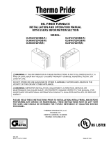
Repair Parts 8
REPAIR PARTS LIST
No. 7 Base No. 11 SS Elbow* B. Elbow Adapter Kit C. Air Cell Kit
PSC-14-4 CH20316 CH20379 CH20301K CH20070-1K
PSC-20-6 CH20316 CH20379 CH20301K CH20070-2K
PSC-30-9 CH20316 CH20379 CH20301K CH20070-3K
PSC-35-10 CH20317 CH20379 CH20301K CH20070-10K
PSC-40-12 CH20316 CH20379 CH20301K CH20070-4K
PSC-48-14 CH20317 CH20379 CH20301K CH20070-6K
PSC-60-20 CH20318 CH20378 CH20302K CH20070-7K
PSC-80-23 CH20317 CH20379 CH20301K CH20070-5K
PSC-85-25 CH20318 CH20378 CH20302K CH20070-8K
PSC-119-35 CH20318 CH20378 CH20302K CH20070-9K
*NOTE: Elbow only: CH20379 = 1" NPT; CH20378 = 1-1/4" NPT.
Key Part
No. Part Description Qty. Number
A Polar Boss Cap Kit (includes CH20294K
Key Nos. 1, 2, 3, 4, 5, 6)
1 Pole Piece Cap 1
2 Valve Stem Nut 1
3 Washer 1
4 C-Clip 2
5 Polar Boss Cap 1
6 O-Ring 1
7 Base 1 See below
B Elbow Adapter Kit (includes See below
Key Nos. 8, 9, 10, 11)
8 O-Ring 1
9 Elbow Adapter 1
10 H-Clip 1
11 SS Elbow 1
C Air Cell Kit (includes See below
Key Nos. 12, 13, 14, 15)
12 Valve Cap 1
13 Valve Core 1
14 Rubber Washer 1
15 Air Cell 1
1
2
3
4
5
6
12
13
15
14
7
8
9
10
11
6163 0310
A
B
C
/