511 McCormick Blvd.
London, ON
Canada
N5W 4C8
General Info/T
ech Support
:
1 855. 247 4200
Online:
www.lifebreath.com
COMMERCIAL HRV
OPERATION AND INSTALLATION
455FD/DD, 650FD/DD, 700FD/DD , 1200FD/DD
69-COMHRV 05-19

2
Table of Contents
The Benefits of HRVs
Location of the HRV for Mounting ............... 3
Specifications - Model 455FD/DD ................ 4
Specifications - Model 700FD/DD ................ 5
Specifications - Model 650FD/DD ................ 6
Specifications - Model 1200FD/DD ............... 7
The Ductwork System
Outside Weatherhoods ................................ 8
Stale Air Return System
Fresh Air Supply System
Adjustable Grilles ........................................ 9
The Integrated HVAC System ...................... 10
Drain Connections
Electrical Connections ................................ 11
HRV Defrost Strategies
Defrost Time Adjustment ............................ 12
Reversing the Supply and Defrost Air Ports ... 13
Optional Ventilation Control
Optional 3 Speed Control ............................ 14
Optional Dehumidistat ................................ 15
Optional Wireless Timer ............................. 16-17
Optional Wireless Repeater
Optional Timer ........................................... 18
Function And Controls ................................. 19
Connecting Optional Digital Controls ............ 20-21
Balancing the HRV ...................................... 22
Reverse Installation ...................................... 25-26
Aircom Relays ............................................ 27
Service and Maintenance ............................. 23-24
Troubleshooting your HRV System .............. 28
Wiring Diagrams ......................................... 29-32
Warranty .................................................... 33
Do not apply electrical power to the unit until
installation has been fully completed (including
low voltage control wiring).
ATTENTION
!
Never install an HRV in a situation where its
normal operation, lack of operation or partial
failure may result in the backdrafting or im-
proper functioning of vented combustion
equipment!
CAUTION
!
Assess how the operation of an HRV may inter-
act with already installed vented combustion
equipment (ie. Gas Furnaces, Oil Furnaces,
Wood Stoves, etc.).
CAUTION
!
Leave this manual with your customer!
TO BE COMPLETED BY CONTRACTOR AFTER INSTALLATION
Installing Contractor
Telephone / Contact
Serial Number
Installation Date Model

3
The Benefits of HRVs
Flexible duct connectors should be installed
between the HRV and the galvanized ductwork.
ATTENTION
!
Heat Recovery Ventilators (HRV) are designed to supply
fresh air to a building while exhausting an equal amount
of stale air from the building. An energy savings is expe-
rienced during the process by reducing the heating (or
cooling) requirements.
HRV - Aluminum Core
During the winter months, the incoming cold fresh air is
warmed by utilizing the heat recovered from the stale air
before it is exhausted to the outdoors. During summer
months when the indoor space is air conditioned, the
Heat Recovery Ventilator will help in cooling the incom-
ing fresh air with the stale air that is being exhausted.
Location of the HRV for Mounting
The HRV must be located in a heated space where the
surrounding air temperature does not fall below 60°F
(16°C). The unit must be mounted level (horizontal) to
obtain proper drainage of water from the heat exchange
element and drip pans. The warranty will be void if these
conditions are not met.
Typically, the HRV is positioned close to an outside wall
or the roof to simplify the connections and keep the
length of insulated ducting required for the fresh air in-
take to a minimum.
A minimum clearance of 30 inches (76 cm) in front of the
HRV is recommended to service the heat exchanger cores
and the filters. The HRV may be mounted on an equip-
ment platform providing the drain hoses are clear and
there is sufficient space to open the doors for servicing.
Fresh
Outdoor Air
Stale Air
to Outdoors
Stale Indoor
Air
Fresh Air
to Indoors
Saddle Installation
Curb Mounted
Vibration Isolators
(Supplied by others)
Threaded Rod
(Supplied by others)
Vibration Isolators
(Supplied by others)
Curb—Wood or Metal
(Supplied by others)
Mount unit on wooden or
metal curb assembly. Unit must be raised an adequate
height for installation and slope of drain lines.
Hang unit with suspended rods
and "U" channel members.
May be an-
chored to
floor, leaving
space for
drain connec-
tions

4
Specifications
455FD/DD
CORES
Modular (2 section) patented aluminum heat recovery cores arranged
for efficient counter-flow ventilation.
MOTORS
Two PSC, 3 speed single shafted, 120 VAC,1.92 Amps each (3.8 total
on high speed). HP- 1/6, 1625 RPM. MCA: 4.8 MOP: 15. Watts - total
on high speed - 437.
FILTERS
Washable air filters in exhaust and supply air streams.
BLOWERS
Slide easily in / out of unit. Centrifugal type rated at 236 L/s (500
CFM) free air delivery. Each air stream has one single shafted motor
driving a centrifugal blower.
CONNECTION DUCT SIZES
Four - 14" x 8" (356 mm x 200 mm).
MOUNTING
Unit to be set on support brackets hung by threaded rod type appa-
ratus (brackets and rods not provided).
CASE
Unit has front and back access doors and electrical panel can be
switched to either side giving the installer flexibility in duct direction.
20 gauge pre-painted galvanized steel (G60) for superior corrosion
resistance. Insulated with foil faced insulation where required to pre-
vent exterior condensation. Drain connections; two - 1/2" (12 mm)
O.D.
ELECTRONICS
Integrated microprocessor circuit board. Built-in interlock contacts.
DEFROST CONTROLS
MODEL 455FD - Interrupts supply air while exhaust air defrosts core.
MODEL 455DD - Supply bypass routes indoor air to defrost core.
WEIGHT 150 lbs. (70 kg) SHIPPING WEIGHT 210 lbs. (90 kg)
CONTROL OPTIONS
99-BC02 Lifebreath Ventilation Control
2 speed fan setting (Low/High)
Humidity control through adjustable Dehumidistat
Compatible with 99-DET02 Wireless Timers
3 wire connection; 20 gauge wire (minimum)
99-500 3 Speed Control
3 Speed Fan setting (Low/Medium/High)
4 wire connection; 20 gauge wire (minimum)
99-DH01 Lifebreath Dehumidistat
Humidity control through adjustable Dehumidistat
3 wire connection; 20 gauge wire (minimum)
TIMER OPTIONS
99-DET01 Lifebreath 20/40/60 Minute Timer
Initiates high speed Ventilation for 20, 40 or 60 minutes
3 wire connection; 20 gauge wire (minimum)
99-DET02 Lifebreath WIRELESS 20/40/60 Minute Timer
Initiates high speed Ventilation for 20, 40 or 60 minutes
Wirelessly connects to main control for ease of installation
40' approximate range
99-RX02 Lifebreath WIRELESS Repeater
Used to extend range of 99-DET02 Wireless Timers when
Timers are out of range
Plugs into 120V power outlet and wirelessly connects to
main control and 99-DET02
PERFORMANCE
AIRFLOWS (Each Air Stream)
TEMPERATURE EFFECTIVENESS
600 (283)
550 (260)
500 (236)
450 (212)
400 (189)
350 (165)
300 (142)
250 (118)
0
0.1
(25)
0.2
(50)
0.3
(75)
0.4
(100)
0.5
(125)
0.6
(150)
0.7
(175)
0.8
(200)
0.9
(225)
EXTERNAL STATIC PRESSURE IN. W.C. (PASCALS)
400 (189)
300 (143)
500 (236)
200 (94)
70%
60%
50%
AIRFLOW IN CFM (L/s)
AHRI 1060 Certified
Core: Contains two 68-222
AIRFLOW IN CFM (L/s)
EFFECTIVENESS
High Speed
Med Speed
Low Speed
WARRANTY
Units carry a 15 year warranty
on the HRV core and a 2 year
replacement parts warranty.
All units conform to CSA and UL
standards
NOTE: All specifications are sub-
ject to change without notice.
Date: ______________________________________
Tag: ____________________ Qty: ______________
Project: ____________________________________
Engineer: ___________________________________
Contractor: _________________________________
Supplier: ___________________________________
Quote #: ___________________________________
Submitted by: _______________________________
SUPPLY AIR
FROM OUTSIDE
DD MODEL ONLY
DEFROST AIR
DD MODEL ONLY
SUPPLY AIR
FROM OUTSIDE
FD MODEL ONLY
EXHAUST AIR
TO OUTSIDE
SUPPLY AIR
TO BUILDING
EXHAUST AIR
FROM BUILDING
NOTE: Service clearance
is 30 in. (760 mm) from
front access doors
FRONT VIEW
DISCHARGE SIDE
INLET SIDE
28 3/4”
(730 mm)
29”
(737 mm)
29”
(737 mm)
33 1/4”
(845 mm)
8”
(200 mm)
14”
(356 mm)
8”
(200 mm)
14”
(356 mm)
4 3/4”
(121 mm)
7 1/2”
(191 mm)
6 1/2”
(165 mm)
6 1/2”
(165 mm)
DIMENSIONS inches (mm)
NOTE: The 455FD/DD model may
easily be reversed in the eld. Refer to
page 25 for installaon instrucons.

5
Specifications
700FD/DD
CORES
Modular (2 section) patented aluminum heat recovery cores arranged
for efficient counter-flow ventilation.
MOTORS
Two PSC, 3 speed single shafted, 120 VAC, 4.5 Amps each (9 total on
high speed). HP-1/4, 1450 RPM. MCA: 11.3 MOP: 15 Watts - total
on high speed - 1032.
FILTERS
Washable air filters in exhaust and supply air streams.
BLOWERS
Slide easily in / out of unit. Centrifugal type rated at 700 CFM (329 L/
s) free air delivery. Each air stream has one single shafted motor driv-
ing a centrifugal blower.
CONNECTION DUCT SIZES - Four - 14" x 8" (356 mm x 200 mm).
MOUNTING
Unit to be set on support brackets hung by threaded rod type appa-
ratus (brackets and rods not provided).
CASE
Unit has front and back access doors and electrical panel can be
switched to either side giving the installer flexibility in duct direction.
20 gauge pre-painted galvanized steel (G60) for superior corrosion
resistance. Insulated with foil faced insulation where required to pre-
vent exterior condensation. Drain connections are two - 1/2" (12 mm)
O.D.
ELECTRONICS
Integrated microprocessor circuit board. Built-in interlock contacts.
DEFROST CONTROLS
MODEL 700FD - Interrupts supply air while exhaust air defrosts core.
MODEL 700DD - Supply bypass routes indoor air to defrost core.
WEIGHT 260 LBS (118 KG) SHIPPING WEIGHT 310 LBS. (141 KG)
CONTROL OPTIONS
99-BC02 Lifebreath Ventilation Control
2 speed fan setting (Low/High)
Humidity control through adjustable Dehumidistat
Compatible with 99-DET02 Wireless Timers
3 wire connection; 20 gauge wire (minimum)
99-500 3 Speed Control
3 Speed Fan setting (Low/Medium/High)
4 wire connection; 20 gauge wire (minimum)
99-DH01 Lifebreath Dehumidistat
Humidity control through adjustable Dehumidistat
3 wire connection; 20 gauge wire (minimum)
TIMER OPTIONS
99-DET01 Lifebreath 20/40/60 Minute Timer
Initiates high speed Ventilation for 20, 40 or 60 minutes
3 wire connection; 20 gauge wire (minimum)
99-DET02 Lifebreath WIRELESS 20/40/60 Minute Timer
Initiates high speed Ventilation for 20, 40 or 60 minutes
Wirelessly connects to main control for ease of installation
40' approximate range
99-RX02 Lifebreath WIRELESS Repeater
Used to extend range of 99-DET02 Wireless Timers when
Timers are out of range
Plugs into 120V power outlet and wirelessly connects to
main control and 99-DET02
FILTER OPTION
99-65-183 2” pleated MERV 8 filter for fresh air stream
PERFORMANCE
AIRFLOWS (Each Air Stream)
TEMPERATURE EFFECTIVENESS
800 (378)
700 (329)
600 (282)
500 (235)
400 (190)
300 (143)
200 (94)
100 (42)
0
0.1
(25)
0.2
(50)
0.3
(75)
0.4
(100)
0.5
(125)
0.6
(150)
0.7
(175)
0.8
(200)
0.9
(225)
EXTERNAL STATIC PRESSURE IN. W.C. (PASCALS)
300
(143)
70%
60%
50%
AIRFLOW IN CFM (L/s)
AHRI 1060 Certified
Core: Contains two 68-222
AIRFLOW IN CFM (L/s)
EFFECTIVENESS
High Speed
Med Speed
Low Speed
WARRANTY
Units carry a 15 year warranty on the HRV
core and a 2 year replacement parts warranty.
All units conform to CSA and UL standards
NOTE: All specifications are subject to change
without notice.
Date: ______________________________________
Tag: ____________________ Qty: ______________
Project: ____________________________________
Engineer: ___________________________________
Contractor: _________________________________
Supplier: ___________________________________
Quote #: ___________________________________
Submitted by: _______________________________
SUPPLY AIR
FROM OUTSIDE
DD MODEL ONLY
DEFROST AIR
DD MODEL ONLY
SUPPLY AIR
FROM OUTSIDE
FD MODEL ONLY
EXHAUST AIR
TO OUTSIDE
SUPPLY AIR
TO BUILDING
EXHAUST AIR
FROM BUILDING
NOTE: Service
clearance is 30 in.
(760 mm) from
front access doors
FRONT VIEW
DISCHARGE SIDE
INLET SIDE
DIMENSIONS inches (mm)
NOTE: The 700FD/DD model may
easily be reversed in the eld. Refer to
page 25 for installaon instrucons.
400
(190)
500
(143)
600
(190)
700
(143)
1.0
(250)
900 (425)

FRONT VIEW
INTERIOR DUCT
CONNECTION SIDE
EXTERIOR DUCT
CONNECTION SIDE
AIRFLOWS (Each Air Stream)
900 (425)
800 (378)
700 (329)
600 (282)
500 (235)
400 (190)
300 (143)
200 (94)
100 (42)
AIRFLOW CFM (L/s)
TOTAL CURRENT DRAW (AMPS) @ 120 VAC
7.0 MED
7.9 HIGH
6.6 LOW
90%
80%
70%
600
(282)
700
(329)
EXTERNAL STATIC PRESSURE IN PASCALS (in. W.C.)
TEMPERATURE EFFECTIVENESS
AIRFLOW IN CFM (
L/s
)
NOTE: Exhaust Relative Humidity (RH) at 40%
EFFECTIVENESS
800
(378)
900
(425)
500
(235)
PERFORMANCE
CORES
Modular (6 section) patented aluminum heat recovery cores arranged for
high efficiency counter-flow ventilation.
MOTORS
Two PSC, 3 speed double shafted, 120 VAC, 3.8 Amps each
(7.6 total on high speed). HP - 1/4, 1625 RPM. Watts - total on High
Speed - 912. MCA: 9.5 MOP: 15
FILTERS
Washable air filters in exhaust and supply air streams.
BLOWERS
Slide easily in / out of unit. Centrifugal type rated at 850 cfm (401 L/s)
free air delivery. Each air stream has one double shafted motor driving
two centrifugal blowers.
CONNECTION DUCT SIZES
Four - 20" x 8" (508 mm x 200 mm). Model 650DD - additional 20" X 8"
defrost port
MOUNTING
Unit to be set on support brackets hung by threaded rod type apparatus
(brackets and rods not provided).
CASE
Unit has front and back access doors and electrical panel can be switched
to either side giving the installer flexibility in duct direction. 20 gauge
pre-painted galvanized steel (G60) for superior corrosion resistance.
Insulated with foil faced insulation where required to prevent exterior
condensation. Drain connection is one - 1/2" (12 mm) O.D.
ELECTRONICS
Integrated microprocessor circuit board. Built-in interlock contacts.
DEFROST CONTROLS
Model 650FD - Interrupts supply air while exhaust air defrosts core.
Model 650DD - Supply bypass routes indoor air to defrost core.
WEIGHT 270 lbs. (120 kg) SHIPPING WEIGHT 350 lbs. (156 kg)
CONTROL OPTIONS
Specifications
650FD/DD
Date: ___________________________________________
Tag: _____________________Qty:___________________
Project: _________________________________________
Engineer: ________________________________________
Contractor: ______________________________________
Supplier: ________________________________________
Quote#: _________________________________________
Submitted by: ____________________________________
DIMENSIONS inches (mm)
99-BC02 Lifebreath Ventilation Control
• 2 speed fan setting (Low/High)
• Humidity control through adjustable Dehumidistat
• Compatible with 99-DET02 Wireless Timers
• 3 wire connection; 20 gauge wire (minimum)
99-500 3 Speed Control
• 3 Speed Fan setting (Low/Medium/High)
• 4 wire connection; 20 gauge wire (minimum)
99-DH01 Lifebreath Dehumidistat
• Humidity control through adjustable Dehumidistat
• 3 wire connection; 20 gauge wire (minimum)
TIMER OPTIONS
•
99-DET01 Lifebreath 20/40/60 Minute Timer
•
Initiates high speed Ventilation for 20, 40 or 60 minutes
3 wire connection; 20 gauge wire (minimum)
•
99-DET02 Lifebreath WIRELESS 20/40/60 Minute Timer
•
Initiates high speed
Ventilation for 20, 40 or 60 minutes
•
Wirelessly connects to main control for ease of installation
40' approximate range
•
99-RX02 Lifebreath WIRELESS Repeater
•
Used to extend range of 99-DET02 Wireless Timers when
Timers are out of range
Plugs into 120V power outlet and wirelessly connects to main
control and 99-DET02
25 (.1) 50 (.2) 75 (.3) 100 (.4) 125 (.5) 150 (.6) 175 (.7) 200 (.8) 225 (.9) 250 (1)
WARRANTY
Units carry a 15 year warranty
on the HRV core and
a 2 year
replacement parts warranty.
NOTE:
The 650FD/DD
model may easily
be reversed in the
field. Refer to
page 25 for
installation
instructions.
All units conform to
CS A and UL
standards
NOTE:
All
specifications are
subject to change
without notice.
AHRI 1060 Certified
Core: Contains six 68-222
20 in
(508 mm)
8 in
(203 mm)
1.75 in
(44 mm)
5.5 in
(140 mm)
11 in
(279 mm)
2 in
(51 mm)
4.75 in
(121 mm)
42 in
(1067 mm)
54 in
(1371 mm)
24.75 in
(629 mm)
SUPPLY AIR
TO BUILDING
EXHAUST AIR
TO OUTSIDE
EXHAUST AIR
FROM BUILDING
SUPPLY AIR
FROM OUTSIDE
DEFROST AIR
DD MODEL ONLY
NOTE:
Service clearance
is 30 in. (760 mm)
from front
access doors
20 in
(508 mm)
8 in
(203 mm)
11 in
(279 mm)
42 in
(1067 mm)
FILTER OPTIONS
99-65-183 2" pleated MERV 8 filter for fresh air stream
6

7
Specifications
1200FD/DD
CORES
Modular (3 section) patented aluminum heat recovery cores arranged
for efficient counter-flow ventilation.
MOTORS
Two PSC, 3 speed double shafted, 120 VAC, 9.4 Amps each (18.8
total on high speed). HP - 1/2, 1625 RPM. Watts - total on high speed
- 2256. MCA: 23.5 MOP: 30
FILTERS
Washable air filters in exhaust and supply air streams.
BLOWERS
Slide easily in / out of unit. Centrifugal type rated at 1200 cfm (566
L/s) free air delivery. Each air stream has one double shafted motor
driving 2 centrifugal blowers.
CONNECTION DUCT SIZES
Four - 20" x 8" (508 mm x 200 mm).
MOUNTING
Unit to be set on support brackets hung by threaded rod type appa-
ratus (brackets and rod not provided).
CASE
Unit has front and back access doors and electrical panel can be
switched to either side giving the installer flexibility in duct direction.
20 gauge pre-painted galvanized steel (G60) for superior corrosion
resistance. Insulated with foil faced insulation where required to pre-
vent exterior condensation. Drain connections; two - 1/2" (12 mm)
O.D.
ELECTRONICS
Integrated microprocessor circuit board. Built-in interlock contacts.
Optional remote speed control.
DEFROST CONTROLS
MODEL 1200FD - Interrupts supply air while exhaust air defrosts core.
MODEL 1200DD - Supply bypass routes indoor air to defrost core.
WEIGHT 285 LBS (130 KG) SHIPPING WEIGHT 335 LBS. (152 KG)
CONTROL OPTIONS
99-BC02 Lifebreath Ventilation Control
2 speed fan setting (Low/High)
Humidity control through adjustable Dehumidistat
Compatible with 99-DET02 Wireless Timers
3 wire connection; 20 gauge wire (minimum)
99-500 3 Speed Control
3 Speed Fan setting (Low/Medium/High)
4 wire connection; 20 gauge wire (minimum)
99-DH01 Lifebreath Dehumidistat
Humidity control through adjustable Dehumidistat
3 wire connection; 20 gauge wire (minimum)
TIMER OPTIONS
99-DET01 Lifebreath 20/40/60 Minute Timer
Initiates high speed Ventilation for 20, 40 or 60 minutes
3 wire connection; 20 gauge wire (minimum)
99-DET02 Lifebreath WIRELESS 20/40/60 Minute Timer
Initiates high speed Ventilation for 20, 40 or 60 minutes
Wirelessly connects to main control for ease of installation
40' approximate range
99-RX02 Lifebreath WIRELESS Repeater
Used to extend range of 99-DET02 Wireless Timers when
Timers are out of range
Plugs into 120V power outlet and wirelessly connects to
main control and 99-DET02
FILTER OPTION
99-65-184 2” pleated MERV 8 filter for fresh air stream
PERFORMANCE
AIRFLOWS (Each Air Stream)
TEMPERATURE EFFECTIVENESS
1600 (755)
1400 (660)
1200 (566)
800 (378)
600 (282)
0
EXTERNAL STATIC PRESSURE IN. W.C. (PASCALS)
500
(235)
70%
60%
50%
AIRFLOW IN CFM (L/s)
AHRI 1060 Certified
Core: Contains three 68-222
AIRFLOW IN CFM (L/s)
EFFECTIVENESS
WARRANTY
Units carry a 15 year war-
ranty on the HRV core and
a 2 year replacement parts
warranty.
All units conform to CSA and
UL standards
NOTE: All specifications are
subject to change without
notice.
Date: ______________________________________
Tag: ____________________ Qty: ______________
Project: ____________________________________
Engineer: ___________________________________
Contractor: _________________________________
Supplier: ___________________________________
Quote #: ___________________________________
Submitted by: _______________________________
SUPPLY AIR
FROM OUTSIDE
DD MODEL ONLY
DEFROST AIR
DD MODEL ONLY
SUPPLY AIR
FROM OUTSIDE
FD MODEL ONLY
EXHAUST AIR
TO OUTSIDE
SUPPLY AIR
TO BUILDING
EXHAUST AIR
FROM BUILDING
NOTE: Service
clearance is 30 in.
(760 mm) from
front access doors
FRONT VIEW
DISCHARGE SIDE
INLET SIDE
DIMENSIONS inches (mm)
NOTE: The 1200FD/DD model may
easily be reversed in the eld. Refer to
page 25 for installaon instrucons.
600
(282)
700
(329)
800
(378)
900
(423)
1000
(472)
1100
(518)
1200
(566)
0.1
(25)
0.2
(50)
0.3
(75)
0.4
(100)
0.5
(125)
0.7
(175)
0.6
(150)
0.8
(200)
0.9
(225)
1.0
(250)
1000 (472)

8
The Ductwork System
Fully insulated ducting with an integral vapour
barrier must be used on all runs passing
through unheated areas in order to avoid con-
densation problems and energy losses from the
air systems.
ATTENTION
!
A properly designed ducting system will allow the HRV to
operate at its maximum efficiency. (Air flow will be re-
stricted by undersized ducting, use of too many elbows,
tees, bends, etc.). Always try to keep duct runs as short
and straight as possible.
NOTE: Fully insulated ducting with an integral vapor
barrier must be used on all runs passing through unheat-
ed areas in order to avoid condensation problems and
energy losses from the air steams.
All joints must be airtight, sealed and impervious to
moisture. See specification sheets for each unit for exact
duct sizes and location.
To minimize pressure drop and noise, galvanized metal
ducts, properly sized, are recommended. Keep ducting
as short as possible and use a minimum of elbows and
tees.
Outside Weatherhoods
The weatherhoods must have built-in “bird” screen with
1/4 in (6.35 mm) minimum mesh to prevent birds and
rodents from entering into the ductwork. Do not use
smaller mesh as it will be very susceptible to plugging
up. Gravity dampers at the vents must not be used as
they will restrict air flow and often “seize up”. The pre-
ferred location of the outside weatherhoods is:
no less than 10 ft. (3 m) apart from each other
at least 18 in (46 cm) above snow line or ground
level
away from sources of contaminants, such as auto-
mobile exhaust fumes, gas meters, garbage cans,
containers, etc.
not exposed to prevailing winds
The outside perimeter of the weatherhood must be
caulked to prevent leakage into the building.
The design and size of the weatherhoods or louvers cho-
sen by the installer must allow for adequate free area.
Water and debris penetration of the system is minimized
when the airflow does not exceed 1000 FPM (5.08 m/s)
free area velocity.
Ducting from the Weatherhoods
Galvanized sheet metal ducting with sufficient cross sec-
tion with an integral single piece vapor barrier should be
used to connect the HRV to the weatherhoods. All duct-
ing must meet UL Class 1 requirements.
A minimum R value of insulation should be equal to 4
(RSI 0.75)
A good bead of high quality caulking (preferably acousti-
cal sealant) and taping with a high quality aluminum foil
tape is recommended to seal the duct to both the HRV
and the weatherhood.
Connecting sections and shorter runs may be flexible
ducting one size larger than the metal equivalent. Use
flexible duct connectors at the HRV to avoid noise trans-
mission.
All duct joints must be secured with screws, rivets or duct
sealant and sealed with aluminum duct tape to prevent
leakage.

9
Stale Air Return System
The stale air return system is used to draw air from the
points in the building where the worst air quality prob-
lems occur. Balancing dampers and/or adjustable grilles
are recommended on all return air lines which are used
during installation to help balance the “draw” from differ-
ent areas of the building.
Alternately, the stale air may be drawn directly from the
return air duct. When this system is used, the air han-
dler’s blower must constantly operate. The exhaust take-
off connection must be at least 3 ft (1 m) from a directly
connected HRV supply duct if both are connected to the
same duct run. Note and compensate for the static pres-
sure of the air handlers return system if the static pres-
sure of the return in the air handler exceeds .1 to .15”
W.C.
A damper located just prior to the HRV is required to
balance the stale air exhausted with the fresh air supply
entering the building.
Return air suction points should be located on the oppo-
site side of the room from the fresh air inlet.
The inlets may be located in the ceiling or high on the
walls and fitted with inlet grilles.
Many commercial activities produce air contaminants in
the form of dusts, fumes, mists, vapors and gases. Con-
taminants should be controlled at the source so they are
not dispersed through the building or allowed to increase
to toxic concentration levels. The ventilator allows for
economical operation of the HVAC system while effective-
ly removing contaminants from the space. In designing
the exhaust portion of the system the exhaust grilles are
situated to remove the contaminants while not allowing
them to enter the breathing zone of the occupants.
For contaminants lighter than air, grilles should be locat-
ed high on the wall. If contaminants are heavier than air,
a lower placement of the grilles will be required. Infor-
mation on a contaminants specific gravity and toxicity
should be available from chemical data sheets.
Fresh Air Supply System
The fresh air supply ductwork from the HRV may be di-
rectly connected to the return air duct of the forced air
system. Check the air flow balance of the HRV with the
air handler blower both “ON” and “OFF” to determine
that it does not imbalance the HRV more than 10%. Al-
so, it is advisable to include a short length of flex duct or
other non-metallic connector in this hard ducted line in
order to keep the HRV acoustically isolated and sepa-
rately grounded (electrically) from the air handler. This
will avoid a possible shock hazard to service people if a
short to ground develops in one of the devices.
It may be necessary to install a separate fresh air supply
ductwork system if the heating is other than forced air.
When installing an HRV, the designer and installer should
be aware of local codes that may require smoke detec-
tors and/or firestats in the HVAC or HRV ductwork.
Because an HRV is designed to bring fresh air into the
building, structures may require supply voltage interrupt
when smoke or flame sensors are triggered, or when a
central fire alarm system is activated.
Supply air grilles may be ceiling or high wall mounted.
Avoid locating incoming fresh air grilles that could cause
a direct draft on the occupants as the incoming air may
be below room temperature. A reheat duct heater can be
installed to improve occupant comfort.
Adjustable Grilles
The use of balancing dampers or adjustable grilles as
supply air diffusers and air exhaust covers are recom-
mended. TECHGRILLES™ are round, efficient, sound
absorbing devices available in 4”, 5”, 6” and 8” (100,
125, 150, and 200 mm) models.
Part# 99-EAG4 4” diameter Techgrille
Part# 99-EAG5 5” diameter Techgrille
Part# 99-EAG6 6” diameter Techgrille
Part# 99-EAG8 8” diameter Techgrille
AIR FLOW
SUPPLY
AIR FLOW
EXHAUST

10
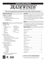
The Integrated HVAC System
When interlocking a rooftop unit with an HRV,
take care to ensure the fans of both units oper-
ate in the correct rotation.
The HRV has become an integral component of the
HVAC system. Figure A shows an HRV unit providing
fresh air directly to the return air plenum of a rooftop
heat/cool unit.
In the balanced airflow system, the HRV exhaust re-
moves stale room air (eg. from lunch room, storage or
copy area) and returns to the space an equal amount of
fresh outdoor air, making the use of an economizer ob-
solete in conjunction with an HRV.
Many buildings have ceiling return air plenum as in Fig-
ure B. Fresh air from the HRV can be introduced directly
into the ceiling space but this should occur near the air
handler’s intake.
By operating the HRV on a 24 hour / 7 day battery
backed timer, the unit can be set to operate only when
occupancy or indoor conditions require the air exchange.
In installations where it is satisfactory to provide general
exhaust from the space, the air to be exhausted may be
taken directly from the return air plenum to the HRV as it
is drawn back to the air handler. Fresh air supplied by
the HRV is then introduced directly into the return air
plenum but at a location closer to the air handler. The air
handler would have a constant running blower to effec-
tively distribute the fresh air and remove the stale air.
Balancing dampers would be located in both the HRV
supply and exhaust ducts between the return air plenum
and the HRV.
NOTE: At no time should the air handler T.E.S.P.
on the return duct exceed that of the HRV .
Figure A
Figure B
CAUTION
!

11
Drain Connections
The HRV must be level for proper drainage of conden-
sate from the drain pans.
Install a loop or "P Trap" in the condensate line and pour
a cup of water into the drain pan. This will create a wa-
ter seal which will prevent odors from being drawn up
the hose and into the fresh air supply of the HRV.
Install the drain pans in the bottom of the HRV so the
drain connections protrude through the holes provided.
Use drain hoses with hose clamps to connect the drain
pan outlets to a floor drain or standpipe. Make sure the
drain line slopes down to the outlet. If this is not possi-
ble, a condensate pump will be required for positive re-
moval of the water. Protect the drain line from freezing.
The HRV and all condensate lines must be in-
stalled in a space where the temperature is
maintained above the freezing point.
CAUTION
!
Drain trap and tubing MUST be below bottom
of door with 1/4" per foot downwards slope
away from unit.
CAUTION
!
DRAIN SPOUT
HRV Cabinet
TAPE
TO DRAIN
TEE CONNECTOR
DRAIN SPOUT
Forming the “P” Trap
Electrical Connections
Electrical Connections
It is recommended that a licensed electrician make all
electrical connections. It is very important that the unit
be properly grounded. The circuit must be sized to han-
dle the F.L.A. indicated on the name tag for the circuit.
WARNING: Verify the polarity of the power coming into
the unit with a test lamp or multimeter. Connect the
multimeter or test lamp probe to the wire being tested
and the other probe to ground. The black line should be
“live”. If the white line is “live” the polarity is reversed
and must be corrected. If both lines are live, the voltage
is not 120VAC. The black open line from the unit should
be connected to the live line and the white open line
should be connected to the neutral line. Some unit have
a safety disconnect rocker switch located just outside of
the electrical control box area. The switch disconnects
the live line. Verify that it is working properly with a
multimeter or test lamp. Always ensure the HRV is
properly grounded before and after testing.
The HRV is designed to operate with ducting.
When first starting the HRV, measure the amp
draw to each motor at each speed to ensure it
is operating at or below the max rating.
CAUTION
!
Maximum AMP Rating
HIGH MED. LOW
1200DD, 1200FD 9.4 6.0 4.5
700DD, 700FD 4.5 3.2 2.4
650DD, 650FD 4.6 3.0 2.3
455DD, 455FD 2.0 1.4 1.0

12
HRV Defrost Strategies (Fan Defrost and Damper Defrost)
Fan Defrost
Models 455FD, 700 FD, 650FD, 1200FD
Fan defrost HRV's are equipped with an electronically
controlled fan defrost system to remove frost that col-
lects on the warm air side of the aluminum heat transfer
surfaces of the heat exchanger core. When the outside
air temperature drops below 27°F (-3°C), defrost is acti-
vated which provides for an automatic defrost cycle.
During the automatic defrost cycle the fresh air supply is
shut off while the exhaust fan continues to operate. This
allows warm inside air to flow through the heat exchang-
er core melting frost accumulation. After the defrost pe-
riod, the fresh air supply fan automatically returns to the
normal speed and fresh outside air continues to be
drawn into the building. Water from the melted frost
collects in the bottom drip pans and drains out through
the bottom drain connections. The defrost cycle repeats
automatically until the air temperature rises above 27°F
(-3°C).
Damper Defrost
Models 455DD, 700DD, 650DD, 1200DD
These damper defrost HRV's have an electronically con-
trolled damper defrost mechanism. If the outside temper-
ature drops below 27°F (-3°C ), the defrost timer is acti-
vated. A motor driven damper door mechanism opens
the defrost port and at the same time closes off the sup-
ply air from outside. After the defrost period, the damper
operates in the opposite direction to close off the defrost
port and reopen the fresh air at the supply port. Defrost
cycle repeats until the temperature again rises above 27°
F (-3°C).
Defrost Time Adjustment
DIP switch #8 will adjust the defrost time. Do not
change any of the other DIP switch settings.
455FD/DD, 700FD/DD, 650FD/DD, 1200FD/DD
Change DIP switch #8 only as illustrated on
this page. Do not adjust any other switches.
ATTENTION
!
Factory Setting (DIP Switch 8 OFF)
The HRV enters defrost mode when outdoor tempera-
tures drop below 27°F (-3°C).
The factory defrost cycle is 4 minutes defrost with a 30
minute run time.
Increased Defrost Time (DIP Switch 8 ON)
Cooler climates may require a more aggressive defrost
cycle.
Positioning DIP switch 8 to ON will initiate a 4 minute
defrost with a 20 minute run time.

13
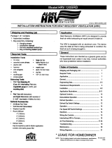
Reversing the Supply and Defrost Air Ports (Damper Defrost Units only- Models 455DD, 650DD,
700DD, 1200DD)
Sometimes installation is easier if the "Supply Air from
Outside" is ducted from the upper left side port (Defrost
Air) instead of the top port.
Changing the functionality of these two ports is easily
accomplished by switching the red and yellow defrost
motor wires at the circuit board. Switch T37 and T39 on
the Aircom circuit board.
Switch T37 (red wire) and T39 (yellow wire) on the Air-
com circuit board if you wish to reverse the "Supply Air
From Outside" and "Pool and Defrost Air" ports.
This illustration shows the factory configuration.
EXHAUST AIR
TO OUTSIDE
SUPPLY AIR
TO BUILDING
EXHAUST AIR
FROM BUIULDING
DEFROST AIR
SUPPLY AIR
FROM OUTSIDE

14
Optional Lifebreath Ventilation Control - Part #99-BC02
Key Features:
2 speed fan setting (LOW / HIGH)
Standby setting (fan OFF)
Electronic Dehumidistat
Compatible with 99-DET02 Wireless Timers
Slim-line design
Connect to 3 wire 20 gauge low voltage
wire
Setting the Ventilation Speed
Press and release the Fan button to select LOW or HIGH fan speed. The corresponding “Indicator Light" will illumi-
nate. If both LO and HI indicator lights are off, the fan is OFF but will turn ON if required by the Dehumidistat or remote
Timer (if installed).
Humidity Control
Your unit will reduce indoor humidity when outdoor humidity levels are lower than indoor humidity levels. This feature is
only effective when the outdoor temperature is below 59˚F (15˚C).
Setting the Dehumidistat
Press and release the Dehumidistat button until the Dehumidistat Light is at the desired setting. After a few seconds
the Dehumidistat light will either flash or be on continuous.
A flashing light indicates the humidity level is higher than the setting and the unit is operating on high speed ventilation.
A continuous light indicates the humidity level is lower than the setting. Refer to the unit's Home Owner’s manual for
instructions on how the Dehumidistat works.
The Dehumidistat will override the current speed setting to HIGH speed.
The Dehumidistat function can be turned OFF by pressing the button until no Dehumidistat light is on.
Note - Only 1 Dehumidistat should be installed in a system.
Humidity
Setting
ON/OFF
Button
Fan Speed
Indicator
Fan
Speed
Dehumidi-
stat Button
ON/OFF
BC02 Operating Instructions:
Turning on the Control
Press and release the ON/OFF button . The light
above will illuminate.
Optional Lifebreath 3 Speed Control - Part #99-500
Key Features:
3 Speed Fan setting (LOW / MEDIUM / HIGH)
4 wire; 20 gauge wire (minimum)
Connect to Red, White, Yellow, Green.
When used in conjunction with the 99-BC02,
the BC02 control must be ON for the 99-500
control to operate. The 99-BC02 will override
the 99-500 control when the Dehumidistat is
operating or the control is set to HIGH speed.
ATTENTION
!
Indicator

15
Optional Lifebreath Dehumidistat - Part #99-DH01
Key Features:
The Dehumidistat measures the indoor humidity
level and will initiate high speed ventilation when
the moisture level in the building exceeds the set
point on the control.
Once the humidity in the building is reduced, the
HRV will revert back to its previous setting.
The Dehumidistat should be set to OFF for all sea-
son except the heating season.
Connect to 3 wire 20 gauge low voltage wire.
Humidity Control
Your HRV will produce a dehumidifying effect when
outdoor humidity levels are lower than indoor humidity
levels. Never use the Dehumidistat feature when out-
door temperatures are above 59 F (15 C).
Note: The indoor humidity level is measured at the
control.
Setting the Dehumidistat
Press and release the Dehumidistat button until the
Dehumidistat Light is at the desired setting. After 5
seconds the Dehumidistat light will either flash or be on
continuous.
A flashing light indicates the humidity level is higher
than the setting and the unit is operating on high
speed ventilation. A continuous light indicates the hu-
midity level is lower than the setting. Refer to the unit's
Operation & Installation Manual for instructions on how
the Dehumidistat works.
Note - Only 1 Dehumidistat should be active on a sys-
tem.
Instruction Card
Dehumidistat
Adjust Button
Dehumidistat Indicator LEDs
Set to the desired humidity lev-
el. High speed ventilation will
initiate when the indoor mois-
ture level exceeds the set point
on the control.

16
Optional Lifebreath Wireless Timer - Part #99-DET02
Note
The wireless Timers and Repeaters must be matched to the
main wall control of the HRV / ERV. This process is called
"Pairing". Multiple Timers and Repeaters can be paired to a
single wall control.
Pairing:
1. Turn on the main wall control by pressing the ON/
OFF button and remove the battery from Timer.
2. Press the left and right buttons simultaneously on
the main wall control ( and ). The bottom row
of 3 LED's will begin flashing. This indicates that the
main control is now in pairing mode. (Figure E)
3. Keep the Timer within 16” of the main wall control
when pairing.
4. Install the battery in the DET02 Timer. All four
lights on the Timer will immediately flash 5 times,
then only the red battery light will remain on for
approximately 12 seconds after which the "40" light
flashes the rev code. 20, 40, 60 lights will flash until
paired or will stop if not paired within 12 seconds.
If pairing was not successful you now must return
to step 1 to restart the pairing process.
5. Press the button on the main wall control to
exit.
To pair additional DET02 Timers with the same wall
control, or if pairing was not successful, repeat steps 1-
6.
When paired, the DET02 Timers can be moved and in-
stalled elsewhere. Estimated range of the Timer is 40’
with no obstructions. A RX02 Repeater may be installed
to increase the range of the Timers.
Test if pairing was successful by pressing the Select
Button and listen for the HRV / ERV to initiate HIGH fan
speed Ventilation.
Un-pairing:
1. Remove the battery from the back of the DET02
Time.
2. 2. Press and hold the Select Button on the front of
the Timer.
3. While holding the Select Button, reinsert the battery
in the Timer. Continue holding the select button
until the LED under "40" begins flashing. The
DET02 Timer will now be unpaired with the main
wall control.
The Timers may be installed onto a flush mounted electri-
cal switch box or it may be surface mounted onto a wall.
Multiple Timers may be installed in a ventilation system.
To increase the range of a wireless Timer, a RX02 Repeat-
er should be used.
Figure A
Figure B
Figure C
Figure D
Figure E
1/8 in hole for
screw and
anchor
1/8 in hole for
screw and
anchor
1/8 in hole for
screw and anchor
1/8 in hole
for screw
and anchor
Face Plate
Back Plate
Break off tab
Break off tab
Alternate Wall Mount
BC02
Control
DET02 Timer
Removable
Back Plate
20/40/60 minute
status lights
Select Button
initiates high
speed ventilation
for 20, 40 or 60
min.
Battery Indicator
Press simultaneously to
initiate pairing mode
NOTE: Your
control may
look different
than the one
shown.

17
Optional Lifebreath Wireless Timer - Part #99-DET02
Installation of Wireless Timer
1. Separate the Face Plate from the Back Plate by firmly pulling apart (Figure A).
2. For mounting the control without a Decora plate, break off top and bottom tabs and refer to Figure C for mounting.
3. Place the Back Plate of the control in the desired location on the wall and pencil mark the top and bottom screw
holes (Figure B or C). Drill two 1/8" holes.
4. Attach the Back Plate to the wall using the 2 supplied screws and anchors.
5. Attach the Face Plate to the Back Plate (Figure A).
Face Plate
Back Plate
Removable
Back Plate
20/40/60 minute
status lights
Select Button initiates
high speed ventilation
for 20, 40 or 60 min.
Battery Indicator
Overview of Lifebreath Wireless 20/40/60 Minute Timer
Initiates HIGH speed Ventilation for 20, 40 or 60 minutes. The 20/40/60
minute Status Lights indicate HIGH speed operation.
Wireless Timers have an estimated range of 40' with no obstructions. To
increase the range of a Wireless Timer a 99-RX02 Repeater may be used.
Using the Wireless Timer
When paired to the main wall control, the Wireless Timer may be moved to
a remote location in the home such as a bathroom.
Pressing the Select Button on the Timer will initiate HIGH speed fan opera-
tion. The corresponding Status Light will illuminate under the number on
the Timer to indicate either 20, 40 or 60 minutes of HIGH speed fan opera-
tion. To cancel the call for HIGH speed fan operation, press the Select
Button until the Status Lights are no longer illuminated.
Replacing the Battery
When the battery needs to be replaced in the Wireless Timer, the red LED
Battery Indicator will illuminate.
To replace the battery, first remove the Face Plate by pulling it off the wall.
On the back of the Timer Face Plate the battery will be exposed. Replace
the battery and re-attach the Face Pate to the Back Plate. Be careful not
to damage the tabs on the Back Plate when re-attaching the Face Plate.
Back of
99-DET02
Face Plate
Battery

18
Optional Lifebreath Wireless Repeater - Part #99-RX02
The RX02 Repeaters are to be plugged directly into a 120V power outlet
1. Turn on the main wall control by pressing the ON/OFF button .
2. Press the left and right buttons simultaneously on the main wall control ( and ). The bottom row of 3
LED's will begin flashing. This indicates that the main control is now in pairing mode.
3. The RX02 Repeater must be powered within 16” of the main wall control for pairing. If an outlet is not
available an extension cord should be used to power the repeater initially for pairing.
4. Plug the RX02 Repeater into the power outlet. The green light will flash after approximately 12 seconds
indicating that the repeater is paired with the main wall control.
5. Press the ON/OFF button on the main wall control to exit pairing mode and the Repeater may now be un-
plugged and moved to its permanent location.
To pair additional RX02 Repeaters with the same wall control, repeat steps 1-5 until
all Repeaters have been paired.
When installed in its permanent location, the green LED will remain solid to indicate
the best location and the Repeater can be moved farther if required. The green LED
will flash to indicate it is in a good location. A red light indicates the Repeater is out of
range and needs to be moved closer to the main wall control.
RX02
Repeater
Power
Plug
Optional Lifebreath 20/40/60 Minute Timer - Part #99-DET01
Operating the Timer
Press and release the Select Button to activate a 20, 40
or 60 minute HIGH speed override cycle. The Light will
illuminate and the unit will run on HIGH speed Ventila-
tion for the selected time. The Light will dim after 10
sec. for run time. The Light will flash during the last 5
min. of the cycle. The Timer connected to the unit will
illuminate for the duration of the override when the Se-
lect Button is pressed.
Lockout Mode
Lockout Mode is useful if you wish to disable the Tim-
ers. The Timer can be set to lockout mode by pressing
and holding the Select Button for five seconds. After 5
sec., the Light will flash; release the Select Button. The
Timer is now in lockout mode. If the Select Button is
pressed during lockout mode the Light will momentarily
illuminate but no override will be initiated.
If lockout mode is initiated when the Timer is activated,
the Timer will continue its timed sequence but will not
allow any further overrides to be initiated. Lockout
mode can be unlocked by pressing and holding the Se-
lect Button for 5 sec. After 5 sec. the Light will stop
flashing. Release the Select Button and the Timer will
now operate normally.
Yellow
Red
Green
Status
Lights
Select Button initiates
high speed Ventilation
for 20, 40 or 60 min.
Timers mount in standard 2” x 4” electrical boxes.
Wire multiple timers individually back to the unit.
Use 3/20 low voltage wire
NOTE
YEL RED GRN
DET
Digital Controls
Terminal strip on
Aircom circuit board
Yellow to YEL
Red to RED
Green to GRN
Use 3/20 wire

19
Function and Controls
Basic Functions
Speed control is obtained by powering 24V to one of the
designated speed taps.
Example:
A jumper between the R terminal and the
G terminal will result in
low
speed operation.
Setup
Select appropriate operational speed by installing the
jumper wire between one of the designated speed taps.
(A jumper wire is factory installed in the low speed posi-
tion.)
Note:
It is recommended to use the optional speed control Part
# 99-500 in order to obtain 3 speed fan control.
SPEED JUMPER
High
R W
Medium
R Y
Low
R G
Optional 3 Speed Control (Part #99-500)
Connect to R, W, Y and G on Thermostat
Optional 20/40/60 Minute Timer
Part# 99-DET01
Boost unit to Ventilation Mode for 20,
40, 60 minutes (no speed change).
Connect up to 4 maximum
Connect to Yellow, Red & Green
Refer to “Connecting Optional
Control” in this manual for instruc-
tions on connecting the optional Life-
breath Ventilation Control
(Part# 99-BC02) and optional Life-
breath Dehumidistat (Part# 99-DH-01)
Connect to Yellow, Red & Green
Jumper wire place-
ment on micropro-
cessor board

20
Connecting Optional Control - Part #99-BC02
1. Separate the Face Plate from the Back
Plate by firmly pulling apart (Figure A).
Be careful not to damage Face Plate Con-
tact Pins.
2. For mounting the control without a Deco-
ra plate, break off top and bottom tabs
and refer to Figure C for mounting.
3. Place the Back Plate of the control in the
desired location on the wall and pencil
mark the top and bottom screw holes
(Figure B or C).
4. Remove the Back Plate and mark the cen-
ter hole for the wires in the middle of the
screw holes. Refer to Figure B or C for
placement.
5. Cut in a 3/4 in by 1 in oval hole in the
wall to allow for the wire opening and
drill (two) 1/8 in holes for the screws and
wall anchors (Figure B or C).
6. Pull 3 wire 20 gauge (min.) 100 ft length
(max.), through the opening in the wall.
7. Connect red, green, and yellow to the
Wiring Terminals located on the Back
Plate (Figure B or C).
8. Attach the Back Plate to the wall using
the 2 supplied screws and anchors.
9. Attach the Face Plate to the Back Plate
(Figure A). Note: Be careful to correctly
align the Face Plate to avoid damaging
the Face Plate Contact Pins.
10. Connect the 3 wire 20 gauge (min.) 100
ft length (max.) to the digital controls
terminal strip located on the Aircom cir-
cuit board (Figure D).
The control is to be surface mounted onto a wall.
Only 1 master control should be installed to a venti-
lation system (the Face Plate on this illustration
may not be exactly the same as yours).
Pay special attention not to damage the Con-
tact Pins when attaching and detaching the
Face Plate. (Figure B)
ATTENTION
!
YEL RED
GRN
DET
Digital Controls
Terminal strip
on Aircom
circuit board
Yellow to YEL
Red to RED
Green to GRN
Use 3/20 wire
Figure A
Keep top / bottom
vent openings clear
Face Plate
Back Plate
Figure B
Figure C
1/8 in hole for
screw and
anchor
1/8 in hole for
screw and
anchor
1/8 in hole for
screw and
anchor
1/8 in hole for
screw and
anchor
1 in x 3/4 in
oval hole for
wire opening
1 in x 3/4 in
oval hole
for wire
opening
Wiring
terminals
Wiring
terminals
Wire hole
centered
between
screw holes
Break off tab
Break off tab
1”
0.75”
0.75”
1.625”
1.625”
Alternate Wall Mount
1”
Figure D
Page is loading ...
Page is loading ...
Page is loading ...
Page is loading ...
Page is loading ...
Page is loading ...
Page is loading ...
Page is loading ...
Page is loading ...
Page is loading ...
Page is loading ...
Page is loading ...
Page is loading ...
Page is loading ...
Page is loading ...
Page is loading ...
/