Montigo PVVEX47-200 Roof Power Vent Operating instructions
- Category
- Fireplaces
- Type
- Operating instructions

XG0531 - 021121
Installation & Maintenance Manual
• Theinstallationofthisreplacemustbedonebya
qualiedandcertiedgasapplianceinstaller.
• Checklocalcodesandreadallinstructionspriorto
installation.
®
C
US
WARNING:
FIRE OR EXPLOSION HAZARD
Failure to follow safety warnings exactly could result in serious injury,
death, or property damage.
—Donotstoreorusegasolineorotherammablevaporsand
liquidsinthevicinityofthisoranyotherappliance.
— WHAT TO DO IF YOU SMELL GAS
• Do not try to light any appliance.
• Do not touch any electrical switch; do not use any
phoneinyourbuilding.
• Leavethebuildingimmediately.
• Immediatelycallyourgassupplierfromaneighbour's
phone. Follow the gas supplier’s instructions.
• Ifyoucannotreachyourgassupplier,callthere
department.
—Installationandservicemustbeperformedbyaqualied
installer,serviceagencyorthegastter.
PVVEX47-200
4/7 EXTERNAL ROOF POWER VENT
Read and understand this manual. Improper installation, adjustment,
alteration, service or maintenance can cause serious injury, property
damage or even death. For assistance or additional information
consult a qualied installer, service agency or the gas supplier.
Some materials used in the manufacturing process of this product can
expose you to Benzene which is known in the State of California to
cause cancer and birth defects or other reproductive harm. For more
information go to www.P65warnings.ca.gov
Installation and service must be performed by a qualied installer,
service agency or the gas tter.
Installer: Leave this manual with the appliance.
Consumer: Retain this manual for suture reference.
NOTICE
CAUTION
DANGER
WARNING

XG0531 - 0211212
General
Congratulations on your purchase of a Montigo Fireplace.
This installation guide covers installation of the Roof mount Power
Vent System only. This system is designed to allow installation of
gas fireplaces that cannot be done with a standard Direct Vent gas
fireplace installation. Only for use on DelRay, Distinction, Divine,
Phenom, that uses the 4/7 and 5/8 venting system.
ONLY USE WITH APPROVED FIREPLACES - see fireplace installation
manual.
Read through the fireplace's installation & maintenance manual,
as it must also be adhered to.
Power Cord Harnesses:
• EPVH10 - 10 foot power cord and harness
• EPVH20 - 20 foot power cord and harness
• EPVH40 - 40 foot power cord and harness
• EPVH50 - 50 foot power cord and harness
• EPVH60 - 60 foot power cord and harness
• EPVH80 - 80 foot power cord and harness
• EPVH100 -100 foot power cord and harness
Introduction
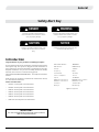
Safety Alert Key
Indicates a hazardous situation which, if
not avoided, WILL result in death or serious
injury or property damage.
Indicates a hazardous situation which, if not
avoided, WILL result in minor or moderate
injury.
Indicates a hazardous situation which, if not
avoided, COULD result in death or serious
injury or property damage.
Indicates practices that are important, but
not related to personal injury.
DANGER
CAUTION
WARNING
NOTICE
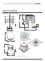
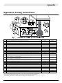
Figure 1 PV Specications
IMPORTANT:
For vent congurations and power vent locations,
refer to replace manual.
Motor Model Number: M2E068DF
Manufacturer : EBM Germany
Voltage: 110 Volts
Frequency: 50 Hz
Current draw: 1.41 Amp
Power consumption: 155 W
Speed: 2850 RPM
Maximum air movement: 400 CFM at zero restriction
Minimum air movement: 50CFM at 2.2" WC
Protection: Thermal switch
Bearings: Ball bearings

XG0531 - 021121 3
General
IMPORTANT MESSAGE: SAVE THESE INSTRUCTIONS
Minimum clearances 1” from vent to all combustible materials
must be maintained. Clearances listed in the fireplace’s Installation
Operation and Maintenance Instructions supersede this number.
Selecting and Installing the Fireplace
When selecting a gas replace for use with the External Power Vent
System, take into consideration the various requirements and limitations
in the venting installation section.
Models Equipped with Electronic Ignition
It is recommended that this system be used with a gas replace equipped
with a Hot Surface Ignition System. Because there is not a pilot in this
system, there is more exibilty on venting requirements. For example
downward vertical vet runs are possible with an HSI system, as outlined
in the Venting Section.
Do not use this appliance if any part has been under water.
Immediately call a qualied service technician to inspect the appliance
and to replace any part of the control system and any gas control that
has been under water
Children and adults should be alerted to the hazards of high surface
temperature and should stay away to avoid burns or clothing ignition
Clothing or other ammable material should not be placed on or near
the appliance
Installation and repair should be done by a qualied service person.
The appliance should be inspected before use and at least annually
by a professional service person. More frequent cleaning might be
required due to excessive lint from carpeting, bedding material, etc. It
is imperative that control compartments, burners, and circulating air
passageways of the appliance be kept clean
When cold air enters the warmer building interior, primarily at the
air intake end, condensation may occur on the exterior of the ex
pipe. To limit this condensation, install insulation over the last
twenty feet of ex pipe. Also, by sloping the last 20'-0" feet of ex
pipe downward toward the exterior of the building, elimination
of most of the condensation problems should occur. Ensure the
termination is securely fastened, and sealed to the ex pipe. Fasten
the termination to exterior of the building with water tight sealant and
the appropriate fasteners.
NOTICE
NOTICE
NOTICE
NOTICE
CAUTION
Contents
Safety Alert Key .................................................................................. 2
Introduction ....................................................................................... 2
Section A: Before You Begin .......................................................................3
Section 1: Dimensions ....................................................................... 4
PVVEX47-200 Product Dimensions ............................................................ 4
Section2:Installingthepowervent ................................................ 5
Venting Installation.........................................................................................5
Multi-Elbow Installations ............................................................................... 5
Downward Vertical Venting ..........................................................................5
Installing the Power Vent .............................................................................. 5
Conduit and Wiring Clearances ..................................................................7
Power Vent Wiring .......................................................................................... 7
Wiring Installation ........................................................................................... 9
Wiring Installation .........................................................................................10
Appendix A: Venting Terminations ................................................ 11
Appendix B: Warranty ..................................................................... 12
Appendix B: Warranty Continued .................................................. 13
Appendix C: Amendment ................................................................ 14
(Gas Fireplace / Equipment sold in the State of Massachusetts)
............................................................................................................ 14
Section A: Before You Begin

XG0531 - 0211214
General
PVVEX47-200 Product Dimensions
Section 1: Dimensions
Figure 2.d Unit dimensions (Tolerance ± ⅛").
2.000
3.950
6.918
A
A
3.660
1.587
19.571
14.288
18.000
3.252
6.997
SECTION A-A
REV.
DESCRIPTION
DATE
APPROVED
B
WAS 24" BASE NOW 18" BASE
09/30/2019
-
1:6
SIZE
DWG. NO.
A
REV.
SHEET 2 OF 4
WEIGHT:
PVVEX47-200 FULL ASSEMBLY
K-FACTOR
MATERIAL
DIMENSIONS ARE IN INCHES
TOLERANCES:
FRACTIONAL
1/32"
TWO PLACE DECIMAL
.015"
THREE PLACE DECIMAL
.005"
ALL BENDS ARE ASSUMED
TO BE 90
UNLESS NOTED
OTHERWISE.
CHECKED BY
DRAWN BY
DB
DATE
NAME
A
1/7/2021
THE INFORMATION CONTAINED IN THIS DRAWING IS THE SOLE PROPERTY OF CANADIAN HEATING PRODUCTS. ANY REPRODUCTION IN PART OR AS A WHOLE WITHOUT THE WRITTEN PERMISSION OF CANADIAN HEATING PRODUCTS IS PROHIBITED.
PROPRIETARY AND CONFIDENTIAL
Y:\Products\Residential Products\Ventilation Systems\Roof Mounr Power Vent PVVEX47-200\PVVEX47-200 FULL ASSEMBLY
Thursday, January 07, 2021 10:05:31 AM
SCALE
MTK
PVVEX47-200
DIMENSIONS
2.000
18.00
[457]
10.560
20.73
18.00
[457]
18.00
[457]
4
[126]
7
[203]
17.025
17.025
EDVRSPVF47
1:12
SIZE
DWG. NO.
A
REV.
SHEET 4 OF 4
WEIGHT:
PVVEX47-200 FULL ASSEMBLY
K-FACTOR
MATERIAL
DIMENSIONS ARE IN INCHES
TOLERANCES:
FRACTIONAL
1/32"
TWO PLACE DECIMAL
.015"
THREE PLACE DECIMAL
.005"
ALL BENDS ARE ASSUMED
TO BE 90
UNLESS NOTED
OTHERWISE.
CHECKED BY
DRAWN BY
DB
DATE
NAME
A
1/7/2021
THE INFORMATION CONTAINED IN THIS DRAWING IS THE SOLE PROPERTY OF CANADIAN HEATING PRODUCTS. ANY REPRODUCTION IN PART OR AS A WHOLE WITHOUT THE WRITTEN PERMISSION OF CANADIAN HEATING PRODUCTS IS PROHIBITED.
PROPRIETARY AND CONFIDENTIAL
Y:\Products\Residential Products\Ventilation Systems\Roof Mounr Power Vent PVVEX47-200\PVVEX47-200 FULL ASSEMBLY
Thursday, January 07, 2021 10:05:31 AM
SCALE
MTK
EDVRSPVF47 - 200
ROUGH IN KIT

5
Installation
XG0531 - 021121
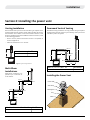
Section2:Installingthepowervent
Figure 3.a Typical Venting Installations.
Venting Installation
External Power Vent System must be used with a gas replace that is
equipped with electronic ignition system. When installing the venting,
the installation must adhere to the Vent Installation Section in the
replace's Installation Operation and Maintenance Instructions, as well
as the following guidelines:
• Ensure that the planned termination location is acceptable as
shown in Appendix A.
• Maximum allowed vent run is 100 feet.
Installing the Power Vent
Downward Vertical Venting
Downward venting installations are only possible with gas replaces
equipped with electronic ignition system. Battery backup cannot be
used with a power vent system.
Multi-Elbow
Installations
Multi-elbow installations are
possible up to a maximum of
six 90° elbows.
V
Max V Max Elbows
100’ feet six 90
Elbow 1
Elbow 2
Elbow 3
Elbow 5
Elbow 4
H2
H1
V1
V2
V3
Max V1 + H1 + V2 + H2 + V3 + H3 Max Elbows
100’ feet six 90
Max V1 + H1 + D + H2 + V3 Max Elbows
100’ feet six 90
Elbow 1
Elbow 2
Elbow 3
Elbow 5
H1
V1
D = 6’ foot
MAX
V3
H2
Elbow 4
Vent Clamp
Framing Box
Vent
Chase
Power Head
Power Vent Components

6
Installation
XG0531 - 021121
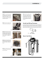
Figure 3.c Installing the Rough-in Kit.
Figure 3.d Installing the Rough-in Kit.
Figure 3.e Unscrewing control cable cover
Figure 3.f Removing strain relief plate.
Figure 3.g
Figure 3.h
Vent Pipe
Control Cable
Step 1: Construct a chase box around the vent penetration with
dimensions as shown.
Step 2: Install the electrical
harness (EPVH-10-100) that will
communicate with the Power
Vent. Run vent pipe from the
replace to the chase. Make sure
the last section is female end up
and is ush with the top of the
chase without going above it.
Step 3: Remove the last section
of vent pipe and put o to the
side to be used later.
Step 4: Unscrew 6 screws
securing the control cable cover
and remove it.
Step 5: Unscrew 2 screws
securing strain relief plate and
remove it.
Step 6: Loosen nut on the strain
relief of the control cable. Pass
control cable through slot in
rough in box making sure the
nut stays is on the opposite
side of the rough in box as the
strain relief. Push the strain
relief through the hole in the
roughin box.
Step 7: Reinstall the strain relief
plate. Make sure the strain relief
nut is above the strain relief
plate. Tighten the nut on the
strain relief.
2.000
3.950
6.918
18.000
18.000
18.000
17.500MAX
FINISHED CURB
17.500MAX
FINISHED CURB
16.250
.625
ROUGH IN KIT
EDVRSPVF47 ROUGH IN KIT
!IMPORTANT!
MAINTAIN AT LEAST
2.00" CLEARANCE
TO COMBUSTIBLES
ALL AROUND THE COLLAR
FRAMING DIMENSIONS
(NTS)
1:12
SIZE
DWG. NO.
A
REV.
SHEET 3 OF 4
WEIGHT:
PVVEX47-200 FULL ASSEMBLY
K-FACTOR
MATERIAL
DIMENSIONS ARE IN INCHES
TOLERANCES:
FRACTIONAL
1/32"
TWO PLACE DECIMAL
.015"
THREE PLACE DECIMAL
.005"
ALL BENDS ARE ASSUMED
TO BE 90
UNLESS NOTED
OTHERWISE.
CHECKED BY
DRAWN BY
DB
DATE
NAME
A
1/7/2021
THE INFORMATION CONTAINED IN THIS DRAWING IS THE SOLE PROPERTY OF CANADIAN HEATING PRODUCTS. ANY REPRODUCTION IN PART OR AS A WHOLE WITHOUT THE WRITTEN PERMISSION OF CANADIAN HEATING PRODUCTS IS PROHIBITED.
PROPRIETARY AND CONFIDENTIAL
Y:\Products\Residential Products\Ventilation Systems\Roof Mounr Power Vent PVVEX47-200\PVVEX47-200 FULL ASSEMBLY
Thursday, January 07, 2021 10:05:31 AM
SCALE
MTK
PVVEX47-200
FRAMING DIMENSIONS

7
Installation
XG0531 - 021121
Figure 3.i Figure 3.n
Figure 3.j
Figure 3.k
Figure 3.l
Figure 3.m
Step 8: Push the molex
connector of the control cable
through the hole in the control
cable cover. Make sure the
molex clicks in place so it does
not fall out. Screw control cable
cover back in place.
Step 13: Place power vent
over chase and fasten with 4
screws on the vertical sides of
the base plate. Silicone of seal
the base plate in any location
necessary to keep the structure
of the building free of water or
moisture.
Step 9: Drop the rough in box
over top of and inside the Chase.
Step 10: Take the last section of
pipe and install the vent clamp
around the pipe. The bottom of
the band should be 6 3/8" from
the top of the pipe. Tighten the
clamp using the supplied nut
and screw.
Step 11: Drop pipe down into
the frame box. The pipe should
be ush with the top of the frame
box. Secure pipe connection
below.
Step 12: Connect power cable
of termination to the molex of
the control cable.
Step #4
Place termination head over chase
and fasten with 4 screws on the
vertical sides of the base plate.
Silicone or seal the base plate in
any location necessary to keep the
structure of the building free of
water or moisture.
20"
Max
20"
Max
10
5
8
"
270
Min
10
5
8
"
270
Min
24
Min
Vent Pipe
Control Cable
Step #1
Construct a chase box around the
vent penetration with the dimensions
as shown here.
Step #2
Install the vent pipe female end up 2"
- 3" from the top of the chase box.
Install the electrical harness (EPVH-
10-100) that will communicate with
the Power Vent module.
Step #3
Install the power vent Rought-in Kit.
Remove the electrical cover plate
from inside of the rough in kit. Pull
the control cable through the slot in
the bottom of the box and insert the
plug into the rectangular hole in the
cover plate. Re-attach the cover
plate. Pull wire harness throught the
supplied hole in the bottom corner of
the rough-in box and snap into the
slot provided.
6⅜
Attachment
screw
locations
Conduit and Wiring Clearances
Connect the power vent harness as outlined. Connect the wiring to the
replace as outlined in the schematic showin in Figure 14 Section 3.
Ensure that the proper clearances are maintained for the wiring and
conduit. When installing the wiring, it must never run above the vent
pipe and it must be at lest 1" clear of all venting and other hot surfaces.
1” Clearance
Wire
Power Vent Wiring
C
Power Vent Wiring
BLUE
BROWN
BLACK
WHITE
BLACK
GREEN
6 PIN MOLEX
CONNECTOR
KEY WAY
BLUE
AIR SWITCH
RED

8
Installation
XG0531 - 021121
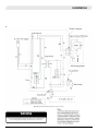
If you do not follow these instructions exactly, a re or explosion may
result causing property damage, personal injury or loss of life.
WARNING
Figure W.a Standard ECB006 Wiring Schematic for Power Vent System.

9
Installation
XG0531 - 021121
If you do not follow these instructions exactly, a re or explosion may
result causing property damage, personal injury or loss of life.
WARNING
1” Clearance
BLACK
WHITE
WHITE
BLACK
BLACK
WHITE
GREEN
VARIABLE SPEED
COMFORT FANS
Lights
ON/OFF
MAIN
Power
120VAC 60 Hz
6 Amps
SPARK
SENSOR
MAIN ON/OFF
SWITCH
YELLOW/GREEN
PILOT
R
ORANGE
GREEN
BLACK
BROWN
YELLOW
ORANGE
6
10
6
Wht
Wht
GREEN
BLACK
POWER
VENT
AIR
SWITC
H
YELLOW
YELLOW
YELLOW
YELLOW
BLACK
GREEN
RED
BROWN
WHITE
CPI/IPI SWITCH
WHITE
SW1
EPVH-**
Connect the wiring to the external power vent termination as outlined
in the previous section, and connect the wiring to the replace as
outlined in the schematic below. Ensure that the proper clearances
are maintained for the wiring and conduit.
• When installing the wiring it must never run above the vent run
and it must be at least 1" clear of all venting.
Wiring Installation
Figure W.b Wiring schematic for Distinction full load, DelRay full load, P38,P42 and P52 with
power vent.
(ECA045PC)

10
Installation
XG0531 - 021121
If you do not follow these instructions exactly, a re or explosion may
result causing property damage, personal injury or loss of life.
WARNING
1” Clearance
Connect the wiring to the external power vent termination as outlined
in the previous section, and connect the wiring to the replace as
outlined in the schematic below. Ensure that the proper clearances
are maintained for the wiring and conduit.
• When installing the wiring it must never run above the vent run
and it must be at least 1" clear of all venting.
Wiring Installation
Figure W.b Wiring schematic for DL,H,L and PL Series
(ECA062PV)
BLACK
WHITE
BLACK
WHITE
GREEN
VARIABLE SPEED
COMFORT FANS
(OPTIONAL)
MAIN
Power
120VAC 60 Hz
6 Amps
SPARK
SENSOR
MAIN ON/OFF
WIRED
TO WALL
SWITCH
OPTIONAL
OR
SWITCH
YELLOW/GREEN
PILOT
R
ORANGE
GREEN
BLACK
BROWN
YELLOW
ORANG
(OPTIONAL) STEPPER MOTOR
E
6
10
6
Wht
Wht
GREEN
BLACK
POWER
VENT
AIR
SWITC
H
YELLOW
YELLOW
YELLOW
YELLOW
BLACK
GREEN
RED
BROWN
WHITE
CPI/IPI SWITCH
WHITE
SW1
EPVH-**

11
Appendix
XG0531 - 021121
Appendix A: Venting Terminations
* Based on CGA B149.1 Natural Gas and Propane installation code. Local codes may vary, please check with local regulatory agency.
** Based on ANSI Z223.1/NFPA 54 National Fuel Gas Code. Local codes may vary, please check with local regulatory agency.
+ A vent shall not terminate directly above a sidewalk or paved driveway which is located between two single family dwellings and serve both dwellings.
++ Only permitted if veranda, porch, deck, or balcony is fully open on a minimum of two sides beneath the floor.
Location Canada* USA**
A clearance to the termination frame above grade, veranda, porch, deck, or balcony 30 inches 30 inches
B clearance to top of doors or operable windows 12 inches 12 inches
C clearance to sides or bottom of door or operable windows 4 feet 4 feet
D clearance to permanently closed window when installed with approved glass penetration termination 0 0
E clearance to permanently closed window Recommended to prevent condensation 30 inches 30 inches
F clearance to ventilated soffit located within a horizontal distance to 24 inches from centerline of termination 22 inches 22 inches
G clearance to unventilated soffit 30 inches 30 inches
H clearance to outside corner 30 inches 30 inches
I clearance to inside corner 30 inches 30 inches
J clearance to each side of the vertical centerline of a metre or regulatory assembly to a maximum vertical distance of 15ft 3 feet 3 feet
K clearance to service regulator vent outlet 3 feet 3 feet
L clearance to non mechanical air supply inlet to the building or combustion air inlet to other
appliance for appliance <= 100.000 BTU/H (30 KW)
12 inches 4 feet
L clearance to non mechanical air supply inlet to the building or combustion air inlet to other
appliance for appliance > 100.000 BTU/H (30 KW)
6 feet 4 feet
M clearance to forced air supply inlet 6 feet 3 feet above air inlet
N+ clearance above paved sidewalk or paved driveway located on public property 7 feet 7 feet
P++ clearance under veranda, porch, deck, or balcony 30 inches 30 inches
Q clearance above roof 2 feet 2 feet
R clearance to adjacent walls and neighboring buildings 30 inches 30 inches
S clearance from corner in recessed location 30 inches 30 inches
T Maximum depth of recessed location 48 inches 48 inches
U Maximum width for back wall of recessed location 60 inches 60 inches
V Horizontal clearance between two terminations that are level 30 inches 30 inches
W Horizontal clearance (centre to centre) between two terminations that are not level 30 inches 30 inches
V
Vertical Detail
Horizontal
Detail

12
Appendix
XG0531 - 021121
Appendix B: Warranty
MONTIGO RESIDENTIAL WARRANTY PROGRAM
Canadian Heating Products Inc. and/or Montigo DelRay Corp
(collectively referred to herein as "The Companies"), warrants the
Montigo gas appliance (referred to herein as 'the appliance') to
be free from defects in materials and workmanship at the time
of manufacture. The gas appliance and related components are
further subject to the terms and conditions set forth below.
ThiswarrantycoversthefollowingMontigoproductseries:
Distinction,H,I,L,LinearPandPL,R,RP,MahanaandDelRay
Component CoveragePeriod LaborCoverage
Firebox, heat exchanger 15 years 1 year
Main burner 15 years 1 year
Gas control valve and related control components
(pilot assembly, spark electrode ame sensors,
thermopile)
1 year 1 year
Electrical components (internal blowers, ignition
control module, wiring, switches, remote control
systems, blower control module, accent bulbs)
1 year 1 year
Firebox media (logset, glass beads, river rocks) 1 year 1 year
Glass (thermal breakage) 1 year 1 year
Plated, painted nishes (including interior reective
glass)*
1 year 1 year
Refractory lining 1 year 1 year
Mesh/Glass safety barriers 1 year 1 year
Power Vent Control box 1 year 1 year
Montigo Venting (excluding terminations) 15 years 1 year
* Exterior painted surfaces exempt
QUALIFICATIONS TO THE WARRANTY
This Warranty only covers gas appliances installed in the United
States or Canada.
To receive the benefits of this warranty, the appliance must
be purchased, installed and serviced annually by a dealer
authorized by The Companies for the warranty to be valid.
The gas appliance must be installed by a licensed professional
in accordance with The Companies' installation instructions
and local building codes. The warranty on the appliance covers
only components manufactured by The Companies. The use of
components manufactured or supplied by other manufacturers
and used in conjunction with the appliance could create serious
safety hazards, may result in the denial of certification by
recognized national safety agencies and could violate local
building codes. Such use may untimely void this warranty. This
warranty does not cover any damages occurring from the
use of any components not manufactured or supplied by The
Companies.
The appliance must be subjected to normal use. The appliance
is designed to burn natural gas (NG) or liquefied petroleum (LP)
only. Burning conventional fireplace fuels such as wood, coal or
any other solid fuel will cause damage to the appliance, produce
excessive temperatures will result in a fire hazard and void all
warranties. This warranty is transferable. The appliance must
remain in its original place of installation to be valid.
If the components of the appliance covered by this warranty
are found to be defective within the time frame stated (see The
Companies investigation of claims), The Companies will, at its
option, replace or repair defective components of the appliance
manufactured by The Companies at no charge and will also
pay for labor costs (in accordance with schedule) incurred in
replacing or repairing components. If repair or replacement
is not commercially practical, The Companies will, at its sole
discretion, fully discharge all obligations under the warranty by
refunding the verified dealer purchase price of the appliance,
excluding the cost of labor unless the labor is covered by the
terms of the warranty.
This warranty covers only parts and labor as provided above.
In no case shall the companies be responsible for materials,
components or construction, which are not manufactured or
supplied by The Companies, or for the labor necessary to install,
repair or remove such materials, components or construction. All
replacement or repair components will be shipped F.O.B. from
the nearest Company factory.
LIMITATION ON LIABILITY
It is agreed and understood that The Companies sole obligation,
and purchaser's exclusive remedy under this warranty, under
any other warranty, expressed or implied, or in contract, tort or
otherwise, shall be limited to repair, replacement or refund as
specified above. The opinion of The Companies with respect to
these matters shall be final.
In no event shall The Companies be responsible for any
incidental or consequential damages caused by (but not limited
to) improper installation, installation by an unqualified or
unauthorized installer, accident, lack of regular maintenance,
user error, abuse, misuse, Acts of God, power surges, floods,
natural disasters, force majeure, defects in its appliance whether
such damage occurs or is discovered before or after replacement
or repair, and whether or not such damage is caused by The
Companies negligence. Some jurisdictions do not allow the
exclusion or limitation of incidental or consequential damages,
so the above limitation or exclusion may not apply to you. The
duration of any implied warranty with respect to the appliance
is limited to the duration of the foregoing warranty. Some
jurisdictions do not allow limitations on how long an implied
warranty lasts, so the above limitation or exclusion may not
apply to you.

13
Appendix
XG0531 - 021121
Appendix B: Warranty Continued
EXCLUSIONS TO WARRANTY
Corrosion or rust of any kind due to a lack of maintenance,
inadequate combustion air or improper venting and corrosive
chemicals/environments, expansion and contraction of metals or
minor movements of components causing noise are not covered
by this warranty.
Willful misconduct (i.e. use of the appliance with problems
known to the purchaser and causing further damages), including
unauthorized or self-performed 'fixing' or exploration of the
appliance's internal workings will void the warranty.
Appliances on which the serial number has been altered, defaced,
removed or made illegible will void the warranty.
Costs incurred for diagnosis, service work, shipping and handling
of defective or replacement parts are not covered under this
warranty.
The published warranties are not applicable for any equipment
manufactured by The Companies that has been sold direct to
the consumer via internet or auction websites. The Companies
do not endorse, approve or certify any online sale of its products
through auction websites, online retailers or any other method
of online sales direct to consumers.
INVESTIGATION OF CLAIMS AGAINST
WARRANTY
The Companies reserve the right to investigate any and all claims
against this warranty and decide upon method of settlement.
The Companies are not responsible for work done without
written consent of The Companies.
The Companies shall in no event be responsible for any warranty
work done without first obtaining the Companies written
consent.
The Companies employees and dealers have no authority to
make any warranties to neither alter this warranty nor authorize
any remedies in addition to or inconsistent with those stated
within this warranty.
IF WARRANTY SERVICE IS NEEDED
To make a claim under this warranty, contact your installing
dealer or contractor. The installing dealer is responsible for
providing service and will contact the companies to initiate
warranted parts replacements. In the event the installing dealer
is unavailable, contact your nearest authorized Montigo dealer
(www.Montigo.com) or contact Montigo direct at techsupport@
montigo.com. Ensure you have your sales receipt and the model
and serial number of your appliance.
DO NOT ATTEMPT TO DO ANY SERVICE WORK YOURSELF
If you cannot locate the installing dealer, or nearest dealer/
distributor, you must notify The Companies in writing.
USA Offices
6955 Salashan Parkway
Ferndale WA, 98248
Canadian Offices
27342 Gloucester Way
Langley, BC V4W 4A1
The terms and conditions of this warranty may be altered or
amended from time to time without prior notice.
WARRANTY PERIOD: Warranty coverage begins on the date of
original purchase. In the case of new construction, warranty
coverage begins on the date of first occupancy of the dwelling
or six months after the sale of the product by an independent,
authorized Company dealer/ distributor, whichever occurs
earlier.

14
Appendix
XG0531 - 021121
(1) Revise NFPA-54 section 10.5.4.2 by adding a second exception as
follows:
Existing chimneys shall be permitted to have their use continued
when a gas conversion burner is installed, and shall be equipped
with a manually reset device that will automatically shut off the
gas to the burner in the event of a sustained back-draft.
(2) Revise 10.8.3 by adding the following additional requirements:
(a) For all side wall horizontally vented gas fueled equipment
installed in every dwelling, building or structure used in whole
or in part for residential purposes, including those owned
or operated by the Commonwealth and where the side wall
exhaust vent termination is less than seven (7) feet above
finished grade in the area of the venting, including but not
limited to decks and porches, the following requirements shall
be satisfied:
1. INSTALLATION OF CARBON MONOXIDE DETECTORS. At the time
of installation of the side wall horizontal vented gas fueled
equipment, the installing plumber or gas fitter shall observe
that a hard wired carbon monoxide detector with an alarm and
battery back-up is installed on the floor level where the gas
equipment is to be installed. In addition, the installing plumber
or gas fitter shall observe that a battery operated or hard wired
carbon monoxide detector with an alarm is installed on each
additional level of the dwelling, building or structure served by
the side wall horizontal vented gas fueled equipment. It shall be
the responsibility of the property owner to secure the services of
qualified licensed professionals for the installation of hard wired
carbon monoxide detectors
a. In the event that the side wall horizontally vented gas fueled
equipment is installed in a crawl space or an attic, the hard
wired carbon monoxide detector with alarm and battery back-
up may be installed on the next adjacent floor level.
b. In the event that the requirements of this subdivision can
not be met at the time of completion of installation, the
owner shall have a period of thirty (30) days to comply with
the above requirements; provided, however, that during said
thirty (30) day period, a battery operated carbon monoxide
detector with an alarm shall be installed.
2. APPROVED CARBON MONOXIDE DETECTORS. Each carbon
monoxide detector as required in accordance with the above
provisions shall comply with NFPA 720 and be ANSI/UL 2042 listed
and IAS certified.
3. SIGNAGE. A metal or plastic identification plate shall be
permanently mounted to the exterior of the building at a
minimum height of eight (8) feet above grade directly in line with
the exhaust vent terminal for the horizontally vented gas fueled
heating appliance or equipment. The sign shall read, in print
size no less than one-half (1/2) inch in size, “GAS VENT DIRECTLY
BELOW. KEEP CLEAR OF ALL OBSTRUCTIONS”.
Appendix C: Amendment
(Gas Fireplace / Equipment sold in the State of Massachusetts)
5.08: Modications to NFPA-54, Chapter 10
4. INSPECTION. The state or local gas inspector of the side wall
horizontally vented gas fueled equipment shall not approve
the installation unless, upon inspection, the inspector observes
carbon monoxide detectors and signage installed in accordance
with the provisions of 248 CMR 5.08(2)(a)1 through 4.
(b) EXEMPTIONS: The following equipment is exempt from 248
CMR 5.08(2)(a)1 through 4:
1. The equipment listed in Chapter 10 entitled “Equipment Not
Required To Be Vented” in the most current edition of NFPA 54 as
adopted by the Board; and
2. Product Approved side wall horizontally vented gas fueled
equipment installed in a room or structure separate from the
dwelling, building or structure used in whole or in part for
residential purposes.
(c) MANUFACTURER REQUIREMENTS - GAS EQUIPMENT VENTING
SYSTEM PROVIDED. When the manufacturer of Product
Approved side wall horizontally vented gas equipment
provides a venting system design or venting system
components with the equipment, the instructions provided
by the manufacturer for installation of the equipment and the
venting system shall include:
1. Detailed instructions for the installation of the venting system
design or the venting system components; and
2. A complete parts list for the venting system design or venting
system.
(d) MANUFACTURER REQUIREMENTS - GAS EQUIPMENT VENTING
SYSTEM NOT PROVIDED. When the manufacturer of a
Product Approved side wall horizontally vented gas fueled
equipment does not provide the parts for venting the flue
gases, but identifies “special venting systems”, the following
requirements shall be satisfied by the manufacturer:
1. The referenced “special venting system” instructions shall
be included with the appliance or equipment installation
instructions; and
2. The “special venting systems” shall be Product Approved by
the Board, and the instructions for that system shall include a
parts list and detailed installation instructions.
(e) A copy of all installation instructions for all Product Approved
side wall horizontally vented gas fueled equipment, all venting
instructions, all parts lists for venting instructions, and/or all
venting design instructions shall remain with the appliance or
equipment at the completion of the installation.
(3) After NFPA-54 section 10.10.4.2 add a new section 10.10.4.3 as
follows:
When more than four gas appliances are to be vented through a
common gas vent or common horizontal vent manifold, a plan of
the proposed vent installation shall be submitted to the Inspector
and the serving gas supplier for review and approval.
Extraction from: Massachusetts Rules and Regulations
5.00: Amendments To 2002 Edition Of ANSI Z223.1-NFPA-54

15
Notes
XG0531 - 021121

XG0531 - 021121
Installation & Maintenance Manual
PVVEX47-200PVVEX47-200
Roof Power VentRoof Power Vent
-
 1
1
-
 2
2
-
 3
3
-
 4
4
-
 5
5
-
 6
6
-
 7
7
-
 8
8
-
 9
9
-
 10
10
-
 11
11
-
 12
12
-
 13
13
-
 14
14
-
 15
15
-
 16
16


Montigo PVVEX47-200 Roof Power Vent Operating instructions
- Category
- Fireplaces
- Type
- Operating instructions
Ask a question and I''ll find the answer in the document
Finding information in a document is now easier with AI
Related papers
-
Montigo PVHEX47-200 Wall Power Vent Operating instructions
-
-
-
-
-
-
-
Montigo H38SVO Installation guide
-
-
Other documents
-
Gibraltar Building Products VD616G Operating instructions
-
 Regency Fireplace Products Energy E18 Owner's manual
-
White Mountain Hearth Rushmore 50 (DVCT50CBP) Owner's manual
-
-
-
-
-
-
-
