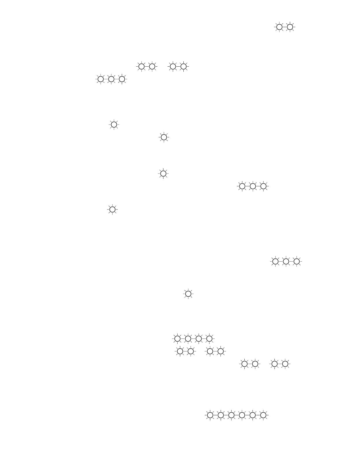
Kaba Mas CL20 User manual

Type
User manual
1
Lock Modes
A lock is shipped from the factory with default lock “setup” values and a pre-set PIN
for unlocking the lock. This is referred to as Factory Mode.
The lock is shipped with a default factory Super Master User PIN that can be set
(i.e., changed) when the lock is in Factory Mode. Once the Super Master User PIN is
set, the Super Master User combination can be used to shelve the lock in the event
that the Master User combination is lost. Refer to the
Super Master Operations
(Document # 3072.026) for more detail.
WARNING:
The setting of the Super Master User PIN is optional, however, if you do
not set the Super Master User PIN before setting the
Master User PIN, all
Super Master User capabilities will be permanently lost.
The lock is removed from Factory Mode when the Master User PIN gets changed.
The lock has two modes of operation: Independent Mode and Supervisory/
Subordinate Mode. Within each operation mode, two access modes are available:
Single User access and Dual User access. In Single User access, only one
combination is required to open the lock. In Dual User access, two combinations
must be correctly and consecutively entered to open the lock.
Independent Mode - When operating in Independent Mode, the Master User can add
Access Users. One (Single User access) or two (Dual User access) combinations are
required to open the lock.
This is the default operation mode for the lock when the
Master User PIN first gets changed.
Supervisory/Subordinate Mode (Super/Sub Mode) - When operating in Super/Sub
Mode, the
Master User can add Supervisors. Subordinate Users must then be added by
and assigned to a Supervisor.
In Single User access, one valid User combination is required to open the lock.
In Dual User access, two valid User combinations are required to open the lock.
If a Supervisor disables lock access for the Subordinate User(s) assigned to a Supervi-
sor ID, the Subordinate User combinations for that Supervisor ID will no longer be valid
combinations for lock access.
To remove a lock from an operational mode, one can “shelve” the lock which places
it in Shelved Mode. Most lock values are returned to the factory default.
Personnel Classifications
There are four different classifications of lock personnel:
Master User - The Master User performs the initial lock setup activities and can also
shelve the lock. There is a maximum of one
Master User per lock. The Master User
combination will also open the lock.
Access User - In Independent mode, a user added by the Master User. An Access User
can open the lock.
Document Number 3073.026 Rev. B2 - 09/07
UNICON
TM
CL SERIES
M
ODEL CL20
OPERATING INSTRUCTIONS
2
Access User
Subordinate
User
Master User
Supervisor
Keypad
Command
Supervisor - In Super/Sub mode, a user added by the Master User who has the ability to
add/delete Subordinate Users. The maximum number of Supervisors per lock is four. A
Supervisor can also open the lock.
Subordinate User - In Super/Sub mode, a user who is added by and assigned to a
Supervisor. Subordinates can open the lock when enabled by a Supervisor.
Access Combination Requirements
A valid access combination allows a user to open a lock. By default a combination is eight
digits long and consists of a 3-digit User ID + a 5-digit User PIN.
The access combination
requirement can be changed to require entry of only the User ID. This decreased
access requirement lessens the security of the lock and is not recommended in most
situations.
Note:
The full 8-digit combination of User ID + PIN is always required for the Master User.
User ID
A User ID is a three-digit number that represents a user. User ID 111 is reserved for the
Master User. A maximum of 125 users are available in the lock (Master User + 124 other
users.) All operations performed by users require the entry of the User’s ID as the first three
digits of the combination. User IDs are assigned by the Master User or by a Supervisor.
In Super/Sub mode User IDs 112, 113, 114 and 115 are reserved for Supervisors. In this
mode, the allocation of users allowed is a Master User, 4 Supervisors and 120 Subordinate
Users.
User PIN
A User Personal Identifier Number (PIN) is five digits. A User PIN can be defined to any
combination of numbers allowed by the keypad. A PIN can also be changed at a later time.
Personnel Activity Chart
The following chart shows the activities that can be performed by each type of user.
Activity
Set Master User PIN (p.6) #1
Change PIN (p.10) #1
Shelve Lock -
Master User (p.11) #3
Add Supervisors or Access Users (p.9) #4
Add Subordinate Users (p. 9) #4
Delete Supervisors or Access Users
(p.9) #5
Delete Subordinate Users (p.9) #5
Set Access/Operating Mode/Lock ID(p. 6) ##1
Enable/Disable Lock Access For ##4 N/A
Subordinates (p.10)
Toggle Sound On/Off (p.7) ##5
Toggle Daylight Savings Time (p.12) ###1
Change Reporting Capabilities (p.7) ###2
Toggle Access Combination Req. (p.12) ###3
Unlock - Independent Mode (p.10) ✓✓N/A N/A
Unlock - Super/Sub Mode (p.10) N/A ✓ ✓
Upload Data to Lock* (p.13) #2 ✓ ✓
Download Data from Lock* (p.14) #2 ✓✓
* Software Based Operations
3
GETTING STARTED
Lock Operating Conventions
The power source for the Unicon CL Lock Series is two CR-2 Lithium 3V batteries.
The lock is activated for operation when a keypad button is pressed. If any
additional keystrokes for an operation are not completed within the allotted time
of 15 seconds between keystrokes, operation abort is indicated by simulta-
neous green and red flashes
G
R
with a beep .
The “3” key is held down as a shift key in order to use the “
¸¸
¸¸
¸” and the “#
function keys. When the “3” shift key is pressed and held followed by the 2 (
¸¸
¸¸
¸)
or the 4 (#) key, a yellow flash displays with a beep to indicate that the keypad is
in “shift” mode.
3 + 4 keys together represents the # key. The # key is used for keypad opera-
tions. For operations requiring multiple # keys, you must release the 3 and 4
keys before pressing keys for another # key selection.
3 + 2 keys together represents the
¸¸
¸¸
¸ key. The
¸¸
¸¸
¸ key is used to clear an
operation or combination entry. If the clear operation is successful, a yellow
flash with a beep is displayed followed by two simultaneous green and red
flashes with beeps.
If the bolt is not retracted within 4-6 seconds after a valid opening combination
is accepted, the lock will “relock”.
In Dual User access, you should not press
¸¸
¸¸
¸ between combination entries. This
action will cancel the attempted access.
Please note the following operational differences based on the type of bolt you have
installed:
Dead Bolt (Manual Locking) Technology:
There is a “locked” position and an “unlocked” positon for the knob on the lock
that is directly related to the manual retraction or extension of the bolt. The knob
must be turned in a clockwise (CW) direction to the “unlocked” position to retract
the bolt and unlock the lock. The knob must be turned counter-clockwise (CCW)
back to the “locked” position to extend the bolt and lock the lock. A “lock closed”
audit record will be recorded indicating that the lock bolt is in the locked
position.
Spring Latch Bolt (Auto Locking) Technology:
There is a “locked” position and an “unlocked” positon for the knob on the lock
that is directly related to the manual retraction or extension of the bolt. The knob
must be turned in a clockwise (CW) direction to the “unlocked” position to retract
the bolt and unlock the lock. Once the knob is released, the lock will automati-
cally relock and a “lock closed” audit record will be recorded indicating that the
lock bolt is in the locked position.
Lock Responses
If sound is toggled “off”, no beeps will sound.
After each keystroke a green flash
G
is displayed with a beep . If the lock
does not respond, the key was not pressed properly.
4
After each accepted step of an operation, simultaneous green and red flashes
G
R
display with a beep , prompting you to enter additional information for the next step of
the operation.
After you have completed all the steps of an operation, two simultaneous green and red
flashes display with beeps
G
R
G
R
if the operation is successful. Three
red flashes
R R R
display with beeps if the operation is unsuccessful, and you
will need to re-key the operation that caused the error.
If a valid combination or combinations are entered to open the lock, the lock will respond
as follows:
· If a valid combination is entered to open the lock, the lock will respond with one
green flash
G
and a beep to indicate that a valid combination has been entered
and then one long green flash
G
displays with a beep to indicate that the motor
has fired and the lock is ready to open.
· If a valid combination is entered to open the lock but the motor does not fire
(motor fire error) or you are outside of a valid access schedule, the lock will
respond with one green flash
G
and a beep to indicate that a valid combina-
tion has been entered but will then display three red flashes
R R R
with
simultaneous beeps
to indicate an error firing the motor.
A long red flash
R
is displayed when the knob is returned to the closed position after a
lock opening (or when lock opening period ends with no open.)
A low battery condition is indicated by ten fast yellow flashes after a valid combination
has been entered. Normal opening operation and responses occur after that, as
described above. For instructions on how to change batteries, see the following section
on
Lock Maintenance
.
A keystroke error or invalid combination is indicated by three red flashes
R R R
with simultaneous beeps .
After five consecutive failed entry attempts (invalid combinations), the lock will be
disabled for three minutes. Slow red flashes
R
display with beeps approx. every 2
seconds during this period. Any additional failed entry attempts (after the first five
consecutive attempts) result in the lock disabling for three minutes after each failed entry
attempt.
When enabling or disabling Subordinate Users, the lock will respond as follows:
· Enabling - four slow green flashes
G G
G
G
with beeps followed by two
simultaneous green and red flashes
G
R
G
R
· Disabling - two simultaneous green and red flashes display
G
R
G
R
When new batteries are installed properly, the lock will indicate this “powered”
condition with simultaneous red, green, and yellow flashes with a beep
followed by
two simultaneous red and green flashes with beeps
.
If new batteries are not installed properly or if batteries are almost dead, the lock
may indicate this condition with six quick red flashes
R R
R R
R R
with
simultaneous beeps
. The batteries must be reinserted properly or replaced.
5
Lock Maintenance
Once you have receive the “battery Low” indication of ten
fast yellow flashes after a valid combination entry, you
should change the batteries in a reasonable amount of time.
Remove the two screws from the battery panel and then
remove the panel. Remove the CR-2 Lithium 3V batteries
and replace with high quality, name brand batteries
(Energizer
®
or Duracell
®
.) The negative (-) end of the
battery should be inserted into the battery cavity first.
WARNING:
The lock MUST NOT be sprayed with water or any cleaning liquid.
Recommended cleaning is to wipe down the lock using a damp cloth or a
towelette. Alcohol is an acceptable disinfectant for medical environments.
Initial Lock Operation
To test successful installation of the lock before you begin lock setup, perform the
following operation.
WARNING:
The container door should remain locked open until testing is complete.
To Unlock Using the Pre-Set PIN
Your lock has been shipped so that any valid User ID for the lock model followed
by the factory pre-set PIN for that User ID will open the lock.
1. Enter any valid three-digit User ID for the lock model followed by the default
factory PIN for the User ID. ( For User ID 111 the default PIN is “12345”. For all
other Users IDs the default PIN is “55255”. )
If the combination is entered successfully, the lock displays one green flash
G
with a beep to indicate that a valid combination has been entered and then
one long green flash
G
with a beep to indicate that the lock is ready to
open.
Note:
A “lock open” audit record is written at this point (with user, date, and time.)
2. Turn the lock knob clockwise (CW) to the “unlocked” position to open the
secured unit (cabinet, cart, drawer, etc.)
Practice opening the lock several times with the pre-set PIN before you set a new
combination.
To Lock
How the lock and container are closed is dependent on the type of bolt you have
installed.
If the lock is a Dead Bolt, the knob must be turned back to the “locked” position to
extend the bolt and lock the lock. A “lock close” audit record will be recorded
indicating that the lock bolt is in the locked position.
If the lock is a Spring Latch Bolt and the lock knob is released, the lock will auto-
matically relock and a “lock close” audit record will be recorded indicating that the
lock bolt is in the locked position.
Battery Panel
+
+
-
-
6
Lock Setup
The lock is shipped with a default factory Super Master User PIN that can be set (i.e.,
changed) when the lock is in Factory Mode. Once the Super Master User PIN is set,
the Super Master User combination can be used to shelve the lock in the event that
the Master User combination is lost.
Warning:
The setting of the Super Master User PIN is optional, however, if
you do not set the Super Master User PIN before setting the Manager
User PIN, all Super Master User capabilities will be permanently lost.
If you do not wish to define a Super Master User combination for your lock, proceed
to the following page to complete the lock setup activities. Otherwise, refer to the
Super Master Operations
sheet for instruction on setting the Super Master PIN.
The following lock setup activities need to be performed by the Master User to
configure the lock for operations when the lock is in Factory Mode or has been
Shelved.
1. Set Master User PIN (p.6)
2. Set lock access mode, operating mode, and assign lock ID for reporting
purposes (p.7)
3. Toggle sound off (Optional - p.7)
4. Change reporting capabilities for lock personnel (Optional - p.7)
Set Master User PIN
Note:
The default PIN assigned to the Master User is “12345”. The Master User
must change this default PIN before any lock operations can be performed.
Once you have successfully opened the lock using the Master User’s factory
combination, the Master User must change the default Master User PIN by
completing the following steps:
1. Press # and then 1.
G
R
2. Enter the three-digit Master User ID 111 followed by the default Master User PIN
12345.
G
R
3. Enter the three-digit Master User ID 111 followed by the new Master User PIN.
G
R
4. Enter the three-digit Master User ID 111 followed by the new Master User PIN
again for verification.
G
R
G
R
5. Record the new PIN and store it in a secure place.
Note:
Once the Master User PIN has been set, the factory combinations (User ID +
default factory PIN) will no longer open the lock. The lock defaults to operating in
Independent mode with Single User access.
7
Set Access Mode, Operating Mode and Assign Lock ID
Caution:
If you switch the operating mode from Independent to Supervisor/Subordinate
mode after users have been added to the lock, you will lose all users except the
Master User and those who have a User ID that is reserved for Supervisors (i.e.,
User IDs 112, 113, 114, 115.)
When you change the access and operating modes, the lock will also prompt you to
enter a four-digit number that will identify the lock in the audit report. This lock ID
assignment is optional. If you do not want to assign an ID to the lock, you can enter
“5555” at the prompt for the lock ID and the assigned lock ID will default to “0000”.
1. Press #, # and then 1.
G
R
2. Enter the Master User combination.
G
R
3. Enter 1 for Single User access or 2 for Dual User access.
G
R
4. Enter 1 or 2 again to verify the access type.
G
R
5. Enter 1 for Independent mode or 2 for Super/Sub mode.
G
R
6. Enter 1 or 2 again to verify the mode.
G
R
7. Enter a four-digit number for the lock ID other than 5555.
G
R
If you do not want to assign a lock ID, enter 5555.
G
R
G
R
8. If you entered a number other than “5555” for lock ID, enter the number again
for verification.
G
R
G
R
Toggle Sound On/Off
The Master User can toggle the sound “on” or “off”. If “on”, one beep sounds each
time the lock LED flashes.
Note:
The default value for the lock sound is “on”. This toggle can be changed at any time
except when the lock is in shelved mode or when the lock is disabled.
1. Press #, # and then 5.
G
R
2. Enter the Master User combination.
G
R
G
R
Change Reporting Capabilities
The default reporting mode of the lock enables all lock personnel (Master User,
Access Users, Supervisors and Subordinate Users) to retrieve audit records or to
retrieve User information. However, the Master User can limit the reporting capabili-
ties.
8
To change the reporting capabilities of lock personnel, complete the following steps:
1. Press #, #, # and then 2.
G
R
2. Enter the Master User combination.
G
R
3. Enter 1 to enable all lock personnel to retrieve reporting information from the
lock. Enter 2 to allow only the Master User (111) and User IDs (112, 113, 114,
115) to retrieve reporting information. Enter 3 to allow only the Master User
(111) to retrieve reporting information.
G
R
4. Enter the one-digit number you entered in Step 3 again for verification.
G
R
G
R
Lock Startup Operations
With the lock set up, you are now ready for startup operations. The following opera-
tions should be performed to enable full capabilities of the lock. The instructions for
performing these operations are located in the Lock Operations section of the
manual.
Master User
1. If in Independent Mode, add Access User(s) to the lock. If in Super/Subordinate
Mode, add Supervisors. (p. 9 -
Add Supervisor(s) or User(s)
operation)
Note:
To add Supervisors, the lock must be operating in Super/Sub mode.
Supervisor(s)
1. Change default PIN (p. 10 -
Change PIN
operation)
2. Add Subordinate User(s) to the lock (p. 9 -
Add Supervisor(s) or User(s)
operation)
Subordinate or Access User(s)
1. Change default user PIN (p. 10 -
Change PIN
operation)
9
LOCK OPERATIONS
Operations found in this section are those that can be completed as needed in the
course of normal lock operation after the lock has been set up.
Add Supervisor(s) or User(s)
The Master User can add an Access User to the lock in Independent mode or can
add a Supervisor to the lock in Super/Sub mode. A Supervisor can add a Subordi-
nate User to the lock in Super/Sub mode. Subordinate Users will be assigned to the
Supervisor who added them.
Note: A maximum of 124 users can be added to the lock.
1. Press # and then 4.
G
R
2. Enter the Master User combination or Supervisor combination.
G
R
3. Enter the new Supervisor or User ID.
G
R
4. Enter the new Supervisor or User ID again for verification.
G
R
5. If additional Supervisors or Users are to be added, repeat Steps 3-4 until all
Supervisors/Users have been added.
6. Enter 111 to end the operation.
G
R
G
R
Note:
The default PIN assigned to a new User or Supervisor ID is “55255”. This
default PIN must be changed by the User before any lock operations can be
performed. Refer to the “Change PIN” section for instructions on changing a User
PIN.
Delete Supervisor(s) or User(s)
Note:
A User can only be deleted by the person who created or who supervises the User
(i.e., the Master User or the Supervisor). If a Supervisor is deleted but not the
Subordinate Users belonging to the Supervisor, the Subordinate Users will be
orphaned and automatically disabled but will still exist in the lock. They will not be
enabled for lock access again until the same Supervisor ID is added back to the
lock and the Supervisor ID PIN has been changed .
1. Press # and then 5.
G
R
2. Enter the Master User combination or the Supervisor combination.
G
R
3. Enter the Supervisor ID or User ID to be deleted.
G
R
4. Enter the Supervisor ID or User ID to be deleted again for verification.
G
R
5. If additional Supervisors or Users are to be deleted, repeat Steps 3-4 until all
Supervisors/Users have been deleted.
6. Enter 111 to end the operation.
G
R
G
R
10
Enable/Disable Lock Access For Subordinates
A Supervisor must complete the following steps to enable/disable lock access for
Subordinate User combination(s):
1. Press #, # and then 4.
G
R
2. Enter a valid Supervisor combination.
G
R
3. Enter the three-digit Supervisor ID of the Supervisor to whom the Subordinate
Users you want to enable/disable are assigned. For example, if the Subordinate
Users you want to enable/disable are assigned to Supervisor ID “112”, you
would enter “112” to enable/disable this group of Subordinate Users.
G
R
4. Enter the three-digit Supervisor ID you entered in Step 3 again for verification.
If you are enabling lock access, four slow green flashes
G
G G G
display
with beeps
followed by two simultaneous green and red flashes with beeps
G
R
G
R
. Any valid Subordinate User combination(s) assigned to
the Supervisor ID can be entered at any time to open the lock.
If you are disabling lock access, two simultaneous green and red flashes
display with beeps
G
R
G
R
. The Subordinate combination(s)
assigned to the Supervisor ID can no longer open the lock until lock access is
again enabled by a Supervisor.
Change PIN
A user (Master, Supervisor, Access User, or Subordinate User) PIN can be changed
at any time (however, a User ID can never be changed.)
Caution:
Before changing a PIN, open the container door to allow testing with the new PIN.
1. Press # and then 1.
G
R
2. Enter the combination (User ID + PIN) of the user for which the PIN is to be
changed.
G
R
Note:
The default PIN for a Supervisor, Access User, or Subordinate User is
“55255”. For security puposes, the Master User PIN should not ever be
changed back to the default PIN of “12345”.
3. Enter the new combination (User ID + PIN) for the user.
G
R
4. Enter the new combination (User ID + PIN) for the user again for verification.
G
R
G
R
5. Record the new PIN and store it in a secure place.
To Unlock
1. Enter a valid access combination. If operating in Single User access and the
combination is entered successfully, the lock displays one green flash
G
with a
beep
to indicate that a valid combination has been entered and then one
long green flash
G
with a beep to indicate that the lock is ready to open.
11
If operating in Dual User access, simultaneous green and red flashes
G
R
display with a beep .
3. For Dual User access, enter the second valid combination or User ID only if the
“PIN Required” status is off. If the combination is entered successfully, the lock
displays one green flash
G
with a beep to indicate that a valid combination
has been entered and then one long green flash
G
with a beep to indicate
that the lock is ready to open.
Note:
A “lock open” audit record is written at this point (with user, date, and time.)
4. Turn the lock knob clockwise (CW) to the “unlocked” position to open the
secured unit (cabinet, cart, drawer, etc.) If the knob is never turned to unlock the
lock, a red flash
R
is diplayed with a beep to indicate that the lock
opening period has ended.
To Lock
How the lock and container are closed is dependent on the type of bolt you have
installed.
If the lock is a Dead Bolt, the knob must be turned CCW back to the “locked”
position to extend the bolt and lock the lock. A “lock close” audit record will be
recorded indicating that the lock bolt is in the locked position.
If the lock is a Spring Bolt and the knob is released, the lock will automatically
relock and a “lock close” audit record will be recorded indicating that the lock bolt is
in the locked position.
A long red flash
R
is displayed with a beep when the knob is returned to the
closed position after the lock opening period has ended. If the knob is returned to
the closed position before the lock opening period has ended, the red flash and
beep do not occur until the lock opening period ends.
Shelve Lock using Master User Combination
To remove a lock from an operational mode, you can “shelve” the lock. This opera-
tion places the lock in Shelved Mode where most lock information is returned to the
factory default settings. The only information retained from the operational mode is
the audit information. If the Super Master is active, it is also unaffected.
1. Press # and then 3.
G
R
2. Enter the Master User combination.
G
R
3. Enter 5.
G
R
4. Enter 5 again for verification.
G
G
G
R
G
R
The lock will now open by entering any valid User ID for the lock model followed by
the default factory PIN for that User ID. (“12345 for User ID 111, 55255 for all other
Users IDs.) You should test the opening of the lock with this combination.
12
Toggle Daylight Savings Time
This feature enables the Master User to “toggle” the Daylight Savings Time (DST)
setting, moving the clock ahead one hour or back by one hour.
1. Press #, #, # and then 1.
G
R
2. Enter the Master User Combination.
The clock in the lock will be set ahead one hour or back one hour depending on
what the previous DST setting was.
2 long green flashes with beeps
G
G
= Moved back 1 hour
4 long green flashes with beeps
G
G
G
G
= Moved ahead 1
hour
Toggle Access Combination Requirement
This feature enables the Master User to “toggle” the access combination require-
ment for lock access. The default access combination requirement is an 8-digit
combination (User ID + PIN), meaning that entry of both the User ID and the PIN are
required for lock access. The access combination requirement can be “toggled” to
require entry of only the User ID to open the lock. This decreased access require-
ment lessens the security of the lock and is not recommended in most situations.
The access requirement can however be toggled back to the default at a later time
to provide more security.
1. Press #, #, # and then 3.
G
R
2. Enter the Master User Combination.
The access combination requirement will be toggled and the new status will be
indicated as follows:
2 long green flashes with beeps
G
G
= User ID only required
4 long green flashes with beeps
G
G
G
G
= User ID + PIN
required
Note:
The value of a PIN is unaffected by the status of the access combination require-
ment.
13
SOFTWARE BASED LOCK OPERATIONS
Upload Data to Lock
As an alternative to defining setup data and user data manually at the lock, certain
types of data can be defined at the PC using the Unicon CL Series Software and the
information can then be uploaded (transferred) to the lock via a Smart Key.
Program Lock
If you choose the “Program the Lock” menu option from the Unicon CL Series PC
software, you can define the following data in a Unicon CL20 lock:
Lock ID
Access Mode
Lock Mode
Sound ON/OFF
Reporting Capabilities
Users
Date & Time
Access Schedules
Note:
The Program Lock operation requires a teal colored (blue green) programming key
fob that has been properly prepared at the PC using the Unicon CL Series Soft-
ware.
To program the lock, complete the following steps:
1. Press # and then 2.
G
R
2. Enter the Master User combination. Short red flashes with beeps
R
begin
to display. From the time these flashes begin, you have 10 seconds to properly
insert the prepared teal programming key fob into the lock key fob reader. If you
do not properly insert the key fob within the 10 second period, short red flashes
followed by three red flashes display with beeps
R
R
R
to indicate
an error and you will need to re-key the operation. If the programming key fob
has not been properly initialized, three red flashes display with beeps
R
R
R
.
3. Ensure that the key fob remains connected to the key reader until the lock
has completed uploading the programming data. Upon completion, two
simultaneous green and red flashes display with beeps
G
R
G
R
indicating that the programming of the lock is complete.
Add/Delete Users
As an alternative to manually adding and deleting users at the lock, they can be
added to and deleted from the system at the PC using the Unicon CL Series
Software. The user data can then be transferred to the lock via a teal colored
programming key fob.
14
Note:
The Add/Delete Users operation requires a teal colored (blue green) programming
key fob that has been properly prepared at the PC using the Unicon CL Series
Software.
The process for adding and deleting user information is the same as that for
programming the lock. (The only difference is that the teal colored programming key
fob has been initialized to add and delete users rather than program the lock.) To
Add/Delete Users, perform Steps 1-3 in the previous “Program Lock” section.
Important Note:
If the programming key fob has been initialized to add Subordinate Users,
the combination for the the Supervisor to whom the Subordinates are assigned can
be entered to perform the “upload data” operation rather than the Master User
combination.
Upload Access Schedules
Access Schedules can be defined at the PC using the Unicon CL Series Software
and then uploaded to the lock via a programming key fob.
Note:
The Upload Access Schedules operation requires a teal colored (blue green)
programming key fob that has been properly prepared at the PC using the Unicon
CL Series Software.
The process for uploading Access Schedules is the same as that for programming
the lock. (The only difference is that the teal colored programming key has been
initialized to upload Access Schedules rather than program the lock.) To Upload
Access Schedules, perform Steps 1-3 in the previous “Program Lock” section.
Upload Time
The current time can be retrieved from the PC using the Unicon CL Series Software
and then uploaded to the lock via a programming key fob.
Note:
The Upload Access Schedules operation requires a teal colored (blue green)
programming key fob that has been properly prepared at the PC using the Unicon
CL Series Software.
The process for uploading time to the lock is the same as that for programming the
lock. (The only difference is that the teal colored programming key has been
initialized to upload the time than program the lock.) To Upload Time, perform Steps
1-3 in the previous “Program Lock” section.
Download Data from Lock
There are two types of data that can be “downloaded” (retrieved) from the Unicon
CL20 locks.
Note:
Data cannot be retrieved from the lock when in factory or shelved mode.
15
Retrieve Audit Records
The lock’s audit feature will track the following types of lock transactions in sequen-
tial order of occurrence:
lock opened
lock closed
users added/deleted
Supervisor enable/disable Subordinate User(s)
PIN activated/changed
wrong try penalty
in Dual access mode, first combination entered
lock date/time set
lock shelved
set access schedules
lock mode changed
audit report retrieved
user table report retrieved
Each transaction will include a date and time stamp. The number of audit records
stored by the lock is 400. If you have purchased the Unicon CL Series Software, the
audit trail data stored in the lock can be downloaded from the lock and taken to the
PC for reporting.
Note:
The retrieve audit records operation requires a red reporting key fob that has been
initialized using the PC software to retrieve audit records. When an audit is
retrieved, it will overwrite any previously existing audit data that is in the key fob.
1. Press # and then 2.
G
R
2. Enter the combination. Short red flashes with beeps
R
begin to display.
From the time these flashes begin, you have 10 seconds to properly insert the
prepared red reporting key fob into the lock key fob reader. If you do not
properly insert the key fob within the 10 second period, short red flashes
followed by three red flashes display with beeps
R
R
R
to indicate
an error and you will need to re-key the operation. If the reporting key fob has
not been properly initialized, three red flashes display with beeps
R
R
R
.
3. Ensure that the key fob remains connected to the key reader until the lock
has completed downloading the reporting data. Upon completion, two
simultaneous green and red flashes display with beeps
G
R
G
R
indicating that the audit data download is complete.
4. Return the key fob to the Unicon CL Series Software PC to be read. Refer to the
software documentation for instructions on reading the reporting key.
16
Notice: Information in this document is subject to change without notice. Kaba Mas shall not be liable
for technical or editorial errors or omissions contained herein; nor for incidental or consequential
damages resulting from the furnishing, performance or use of this material.
© 2006 Kaba Mas Corporation. All rights reserved.
PowerStar Technology, Auditcon, and Smart Key are registered trademarks of Kaba Mas Corporation in
the United States and/or other countries.
This product is covered by one or more of the following U.S. patents:
4,803,860 5,170,431 5,265,452 5,271,253 5,410,301 5,451,934 5,488,358 5,488,660
5,493,279 5,511,401 5,590,917 5,592,838 5,709,114 5,774,058 5,774,059 5,870,914
5,873,276 5,881,589 5,893,283 5,896,026 D366,822 D388,308 D388,309
Kaba Mas Corporation
749 W. Short Street, Lexington, KY 40508 USA
Phone: (859) 253-4744 FAX: (859) 255-2655
Technical Support: (800) 950-4744
www.kaba-mas.com
Retrieve User Table
The lock’s User information reporting feature will list the following information for all
Users except the Master User:
All current User IDs (those that currently exist in the lock)
User ID of the Supervisor (in Super/Sub mode) who created the User
Note:
The Retrieve User information operation requires a red reporting key fob that has
been initialized using the PC software to retrieve User information. When a user
table is retrieved, it will overwrite any previously existing user data that is in the key
fob.
The process for retrieving User Table information is the same as that for retrieving
audit information (The only difference is that the red reporting key fob has been
initialized to retrieve User Table information rather than Audit information). To retrieve
User Table information, perform Steps 1-4 in the previous “Retrieve Audit Records”
section.
  • Page 1 1
  • Page 2 2
  • Page 3 3
  • Page 4 4
  • Page 5 5
  • Page 6 6
  • Page 7 7
  • Page 8 8
  • Page 9 9
  • Page 10 10
  • Page 11 11
  • Page 12 12
  • Page 13 13
  • Page 14 14
  • Page 15 15
  • Page 16 16

Kaba Mas CL20 User manual

Type
User manual

Ask a question and I''ll find the answer in the document

Finding information in a document is now easier with AI