Page is loading ...

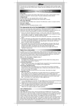
The Maxima Series antenna system is made for high directivity consisting of two antennas.
In order to secure the clear range, please install Maxima Series antenna as shown below.
TX
TX TX
TX
RX
90
Recommended installation
method to optimize
receiver performance
CH1
CH2
CH3
CH4
CH5
CH6
CH7
CH8 BAT/9
HITEC 2.4GHz
Maxima Series
Receiver Instruction
Hitec Service
12115 Paine St. Poway CA 92064
1-858-748-6948
E-mail: service@hitecrcd.com
Introduction
Service & Support
Hitec Customer Service
Help is available from the Hitec oce through phone support and e-mail inquiries.
Our US oce is generally open Monday thru Friday, 8:00AM to 4:30PM PST. These hours and days may vary by
season. Every attempt is made to answer every incoming service call. Should you reach our voicemail, leave
your name and number and a sta member will return your call.
Hitec Web Site
Make plans to visit the Hitec website, www.hitecrcd.com, on a regular basis. Not only is it full of specs and
other information about the entire Hitec product line, our website’s FAQ pages will eventually hold valuable
information and program updates about the Spectra 2.4 module and Optima series of receivers.
The On-Line Community
One of the benets of the extensive R/C online community is the vast wealth of archived knowledge available.
Hitec sponsors forums on most of the popular R/C websites where a Hitec sta member or representative tries
to answer all manner of product related questions. Bringing together strangers with common interests is
proving to be one of the greatest gifts of the internet. If past history is any guide to the future, we are certain
forums will be started about the Hitec 2.4 system and several are certain to stand out as valuable archives of
information.
Warranty and Non-Warranty Service
All Hitec products carry a two year from date-of-purchase warranty against manufacturer’s defects. Our trained
and professional service representatives will determine if the item will be repaired or replaced. To provide all
the necessary information we need to administrate your repair, visit our website at www.hitecrcd.com and
download the repair form, ll it out and send in your item for repair.
Thank you for your purchase of the Hitec Adaptive Frequency Hopping Spread Spectrum (AFHSS) 2.4GHz
module and receiver system. This manual contains the complete directions on how to use the Maxima series of
receiver. We encourage you to review the entire manual before using these products.
Electric powered aircraft with Electronic Speed Control
Use this method on electric planes using ESC’s providing power to the receiver and servo functions.
Maxima Series Receiver Specications & Features
Antenna installation
Receiver Connection Diagrams
Warning!
1. For maximum performance, it is recommended to position the antenna at a 90 degree angle as
shown in the picture below.
2. The receiver antenna should not be placed near the engine, metal parts, or high current batteries.
3. It is strongly recommended to use Hitec ‘s genuine Heavy Duty High Channel Switch Harness with
Receiver Charger Cord (Stock#. 54407S) for all Maxima series receivers.
Full Range AFHSS 2.4GHz Receivers
1. Function Button
- Used for binding the receiver to a module or Hitec 2.4 built-in transmitters,
entering the FAIL-SAFE or Hold feature.
2. Dual LED Status Indicator
- Indicates the set-up process codes and current status of the receiver.
3. Channel Output and Battery Input Ports
- The ports for battery power input and servos, gyros and other accessories output port are located at the
side end of the Maxima receivers.
4. Low Battery Warning
- If once receiver's battery levels reach below 3.6V, RED LED will be ashing.
5. FAIL-SAFE/Hold Mode Selectable
- Servos and other accessories position can be set with a FAIL-SAFE point, if power to the receiver is lost.
See page 2 for details.
Operating Voltage for Maxima series : 3.7~9.0V From receiver battery power or speed control (ESC) power.
Max Current Consumption : 30mA
Recommended Position
CH1
CH2
CH3
CH4
CH5
CH6
CH7
CH8 BAT/9
SERVOSERVO SERVO SERVO
Receiver
Battery
SERVO
Engine
CH1
CH2
CH3
CH4
CH5
CH6
CH7
CH8 BAT/9
SERVOSERVO SERVO SERVO
Power Battery
Motor
SERVO
BEC
ESC
MAXIMA 9
MAXIMA 6
Receiver Model Size Weight
Stock Number
MAXIMA 6 1.29 x 0.81 x 0.42in (33 x 20.8 x 10.7mm) 0.22oz (6.4g) 27524
MAXIMA 9 1.45 x 0.96 x 0.57in (37 x 24.4 x 14.6mm) 0.28oz (8.1g) 27525
Glow, gas or electric powered aircraft using a separate receiver battery supply.
Follow this connection diagram when using a regulated Li-Po, or 4.8 to 6V receiver battery.
Caution
Maxima series is designed for Hitec High-Response Radio such as Aurora 9X, please check the
compatibility. (Aurora 9 cannot be used with Maxima series receiver)
And, please USE ONLY Digital SERVO for your purpose. Analog servo cannot be used with
Maxima series
CH1
CH2
CH3
CH4
CH5
CH6
CH7
CH8
BAT/9
version 1.0

- If FAIL-SAFE is deactivated, the FAIL-SAFE position settings are also deleted!
- The FAIL-SAFE settings should be checked every time before you run the engine/motor.
Note
FAIL-SAFE and Hold Mode Setup
If you use the FAIL-SAFE function, and set it up properly, should the receiver signal somehow be interrupted or
interference were to occur, the servos will move to your pre-set FAIL-SAFE point you previously stored in the
receiver during the FAIL-SAFE set-up.
If FAIL-SAFE has not been activated, the signal is switched o after the HOLD period of 1 sec. This means that
the servos become “soft” and remain in their last commanded position under no load (this may equate to
full-throttle!), until a valid signal is picked up again.
In the interests of safety, we recommend that FAIL-SAFE should always be activated, and the FAIL-SAFE settings
should be selected so as to bring the model to a non-critical situation. (e.g. motor idle / electric motor OFF,
control surfaces neutral, airbrakes extended, aero-tow release open, etc.)
Testing the FAIL-SAFE Setting
a. Move the sticks to positions other than the FAIL-SAFE settings, and then switch o the transmitter.
The servos should now move to the FAIL-SAFE positions previously stored, after the I sec HOLD period
How to turn FAIL-SAFE O and reactivate the Hold Mode
a. Switch on the transmitter, then the receiver. Wait for the system to boot and you have control over the model.
b. Press and hold the receiver function button for 6 seconds and release it. After 2 seconds the red and
blue LEDs will blink rapidly.
c. Immediately press the button once.
d. FAIL-SAFE Mode is now deactivated and HOLD mode is activated.
e. Turn the transmitter o, then the receiver o.
f. Turn the system back on to use it.
Fail-Safe position
Switch on both.
Wait for the system to boot and control over
the model.
Press and hold the button on the receiver until LED turns o
(approx. 6 second)
Release the button. After 2 seconds both red and blue LEDs blink alternately,
the receiver will count 5 seconds during that time move all the transmitter
sticks and other controls to the desired FAIL-SAFE positions
(e.g. motor idle, control surfaces neutral), and hold until blink stops.
When Blink stops, the system will temporary
remember the FAIL-SAFE position and turn o
the system to save and exit.
Link (ID-Setup or Bind)
Your Hitec AFHSS system uses a communication protocol that links and binds the Hitec 2.4GHz receiver to
your transmitter. Once the receiver and module are “bound”, no other transmitter can interfere with your
receiver during its operation. In the case of multiple model memory transmitters, you can bind as many Hitec
2.4GHz receivers to your transmitter, one per model memory as necessary.
Each module and receiver set is paired at the factory for your convenience.
Use one of the following binding methods to bind additional Hitec 2.4GHz receivers to your transmitter.
2Sec.
6Sec.
Please select the Maxima on the Receivers series menu , and touch the “Link” icon and then touch
“Yes” for conrn.
Turn On the transmitter, and touch the “Yes”
in Transmitter
Touch the System menu.
Touch the “Spectra” icon.
Link (ID-Setting)
Too Close: Less than 50Cm(18in)
Too Far: More than 5M(15ft)
- Link must be done within 15ft(5m) of the transmitter and receiver.
- Transmitter and receiver need to be at least 18in(50cm) from each other to link properly.
Note
Touch “Binding” icon. and then touch “Yes” for Binding
Press and hold the link button on Receiver and turn on the power.
Release the link button and Maxima’s.
Both RED and BLUE LEDs will be blinked rapidly
to nd the transmitter signal.
When LED blinking is stop, press [OK]
After reboot receiver, please check turn on Blue LED on receiver
CH1
CH2
CH3
CH4
CH5
CH6
CH7
CH8
BAT/9
CH1
CH2
CH3
CH4
CH5
CH6
CH7
CH8
BAT/9
CH1
CH2
CH3
CH4
CH5
CH6
CH7
CH8
BAT/9
Good work
Caution
( Blue LED will be solid on )
If all function work well press [Finish] icon on screen to nish binding
Control Check
If all function “Do not” work well, Please go back to step “6” and repeat the binding again
8
9
CH1
CH2
CH3
CH4
CH5
CH6
CH7
CH8
BAT/9
CH1
CH2
CH3
CH4
CH5
CH6
CH7
CH8
BAT/9
CH1
CH2
CH3
CH4
CH5
CH6
CH7
CH8
BAT/9
CH1
CH2
CH3
CH4
CH5
CH6
CH7
CH8
BAT/9
CH1
CH2
CH3
CH4
CH5
CH6
CH7
CH8
BAT/9
CH1
CH2
CH3
CH4
CH5
CH6
CH7
CH8
BAT/9
CH1
CH2
CH3
CH4
CH5
CH6
CH7
CH8
BAT/9
CH1
CH2
CH3
CH4
CH5
CH6
CH7
CH8
BAT/9
www.hitecrcd.com
/