Bauknecht DDEI 5890 AL Program Chart

Category
Cooker hoods
Type
Program Chart

This manual is also suitable for

5019 418 33000
DDEI 5890
INSTALLATIONSANGABEN
Mindestabstand zur Kochfläche: 60 cm (Elektroplatten), 75 cm (Gas-, Öl-
oder Kohleflammen). Folgen Sie bei der Installation der Nummerierung
(1
Ö
2
Ö
3
Ö
.....) und den jeweiligen Anleitungen. Schließen Sie das Gerät
erst nach erfolgter Installation an die Stromversorgung an. Den Stecker
der Dunstabzugshaube müssen Sie mit einer normgerechten und gut
zugänglichen Steckdose verbinden. Ist die Dunstabzugshaube nicht mit
Stecker versehen (direkter Netzanschluss), müssen Sie einen zweipoligen,
normgerechten und gut zugänglichen Schalter mit Kontakten im Abstand
von mindestens 3 mm einbauen.
INSTALLATION SHEET
Minimum height above cooker: 60 cm (electric cookers), 75 cm (gas, gas
oil or coal cookers). To assemble follow the numbers (1
Ö
2
Ö
3
Ö
.....) and
relative instructions. Do not connect the appliance to the electrical power
supply until installation is completed. If the appliance is fitted with a
power plug connect the hood to a socket complying with current
standards and located in an easily accessible point. If the appliance does
not have a plug (direct connection to the power supply) fit a two-pole
switch to standards, with minimum break distance between contacts of
3 mm (easily accessible).
FICHE D'INSTALLATION
Distance minimale par rapport à la cuisinière : 60 cm (cuisinière
électrique), 75 cm (cuisinière à gaz, mazout ou charbon). Pour le montage,
suivez la numérotation (1
Ö
2
Ö
3
Ö
.....) et les instructions correspondantes.
Ne branchez pas l'appareil tant que l'installation n'est pas terminée. Si
l'appareil est muni d'une fiche, branchez-la dans une prise conforme aux
normes en vigueur, installée dans un endroit facile d'accès. Si la hotte est
dépourvue de fiche (branchement direct sur le réseau), appliquez un
interrupteur bipolaire conforme aux normes, ayant une ouverture
minimale de 3 mm (accessible).
INSTALLATIEKAART
Minimumafstand tot het kooktoestel: 60 cm (elektrische kooktoestellen),
75 cm (kooktoestellen op gas, olie of kolen). Volg voor de montage de
nummering (1
Ö
2
Ö
3
Ö
.....) en de bijbehorende aanwijzingen. Geef het
apparaat geen stroom totdat de installatie geheel voltooid is. Als het
apparaat voorzien is van een stekker, moet de wasemkap worden
aangesloten op een stopcontact dat aan de geldende voorschriften
voldoet en op een goed bereikbare plaats zit. In het geval dat de kap geen
stekker heeft (directe aansluiting op het elektriciteitsnet) dient u een
tweepolige schakelaar te gebruiken met een afstand tussen de contacten
van minstens 3 mm, die aan de geldende voorschriften voldoet (en
bereikbaar is).
D
GB
F
NL
41833000.fm5 Page 1 Wednesday, April 4, 2001 3:45 PM
5019 418 33000
DDEI 5890
FICHA DE INSTALACIÓN
Distancia mínima desde los fuegos: 60 cm (fuegos eléctricos), 75 cm
(fuegos de gas, gasóleo o carbón). Para efectuar el montaje siga la
numeración (1
Ö
2
Ö
3
Ö
.....) y las instrucciones. No conecte el aparato a la
corriente eléctrica hasta que la instalación esté completamente finalizada.
Si la campana está provista de clavija, conéctela a un enchufe de corriente
conforme a las normativas vigentes, situado en una zona accesible. Si la
campana carece de clavija (conexión directa a la red), se debe instalar un
interruptor bipolar homologado con una distancia de abertura de los
contactos no inferior a 3 mm (y situado en una posición accesible).
FICHA DE INSTALAÇÃO
Distância mínima dos fogões: 60 cm (fogões eléctricos), 75 cm (fogões a
gás, óleo ou carbono). Para a montagem, siga a numeração (1
Ö
2
Ö
3
Ö
.....)
e as respectivas instruções. Não ligue o aparelho à corrente eléctrica até a
instalação estar concluída. Se o aparelho está equipado com uma ficha,
ligue o exaustor a uma tomada conforme as normas em vigor, e coloque-
a numa zona acessível. Se o exaustor não estiver equipado com uma ficha
(ligação directa com a rede eléctrica) aplique um interruptor bipolar
segundo as normas com uma distância dos contactos à abertura não
inferior a 3 mm (acessível).
SCHEDA INSTALLAZIONE
Distanza minima dai fuochi: 60 cm (fuochi elettrici), 75 cm (fuochi a gas,
gasolio o carbone). Per il montaggio seguire la numerazione (1
Ö
2
Ö
3
Ö
.....)
e le istruzioni relative. Non dare corrente allapparecchio finché
linstallazione non è totalmente completata. Se lapparecchio è provvisto
di spina allacciare la cappa ad una presa conforme alle norme vigenti
posta in zona accessibile. Se lapparecchio è sprovvisto di spina
(collegamento diretto alla rete) applicare un interruttore bipolare a
norme con una distanza dei contatti in apertura non inferiore a 3 mm
(accessibile).
ùüùü+ùùùþ
ü$12.)12.1.)2"0120" FP02!"0120" FP0120"
.0! #02!0. #0! # +.22  21.  #1202
.!1
Ö
Ö
Ö
.2"1$02" /0"2! 3 / 2020002!)
!0*.21#10#!2  !&12"0.212.1"ù
. !! 32!."/.203"1#/1202 0!.102&. 1+ #
!102.10! 101 10ü . !! 32!."/0/.203"
.0#0."1*/0102 /2# 2  02120./ )/.)210
2&. 1+00$12  .02.*2&0.3+ PP10
! 101 10
E
P
I
*5
41833000.fm5 Page 2 Wednesday, April 4, 2001 3:45 PM
5019 418 33000
DDEI 5890
41833000.fm5 Page 3 Wednesday, April 4, 2001 3:45 PM
5019 418 33000
DDEI 5890
41833000.fm5 Page 4 Wednesday, April 4, 2001 3:45 PM
5019 418 33000
DDEI 5890
vordere Hälfte
front section
partie avant
voorste gedeelte
sección anterior
secção anterior
sezione anteriore
!)1 %
41833000.fm5 Page 5 Wednesday, April 4, 2001 3:45 PM
5019 418 33000
DDEI 5890
Preliminary information for installing the hood:
Expansion plugs are provided to secure the hood to most types of ceilings. However, a qualified technician must
verify suitability of the materials in accordance with the type of ceiling. The ceiling must be strong enough to take
the weight of the hood.
During electrical connection ensure the power supply is disconnected at the domestic main switch.
1.
Adjust extension of the hood support structure, as the final height of the hood depends on this, and remember
that with installation completed the hood must be at least 60 cm above the cook-top for electric cookers and
75 cm for gas or mixed cookers.
2.
Fix the two sections of the structure using 8 screws.
3.
Place the ceiling hole diagram directly above the cook-top (the centre of the diagram must match the centre
of the cook-top and the edges must be parallel to the sides of the cook-top - the side of the diagram with the
wording FRONT corresponds to the control panel side). Prepare the electrical connection.
4.
Drill as shown (6 holes for 6 wall plugs - 4 plugs for fixture), screw the outer screws using the key supplied)
leaving a space of about 1 cm. between the screw head and the ceiling.
5.
Fit the tube supplied into the truss and connect it to the motor compartment connection ring.
6.
Hook the truss to the 4 screws (see step 4).
CAUTION! The side of the truss with connection box corresponds to the side of the control panel with hood
assembled.
7.
Tighten the 4 screws.
8.
Insert and tighten another 2 screws in the remaining free holes for secure fixing.
9.
Carry out the electrical connection to the mains power supply, only turn on the power supply upon completion
of assembly.
10.
Hook the hood onto the truss, ensuring it fits properly - to hook the hood onto the truss partially tighten 4
screws (see illustrations 10 and 12).
11.
Secure the hood to the truss using two screws; this will also help centre the two sections.
12.
Tighten the 4 screws securing the truss to the hood.
13.
Carry out electrical connection of bulbs (13a) and control panel (13b).
14.
For extractor versions (14A), connect the other end of the exhaust pipe to the domestic flue.
For filter versions (14F), fit deflector F to the truss and secure it to the bracket supplied using 4 screws, then
connect the exhaust pipe to the connection ring located on the deflector.
15.
Fit the nuts with fixing hooks supplied inside the top and bottom sections of the flues at the rectangular slots.
A total of 10 nuts must be fitted.
16.
Join the two top sections of the flue to cover the truss so that one of the slots on the sections is situated on the
same side of the control panel and the other on the opposite side.
Screw the two sections together with 4 screws (2 each side - see the plan diagram for joining the two sections).
17.
Fix the top flue assembly to the truss, near the ceiling, with two screws (one each side).
18.
Join the two bottom sections of the flue covering the truss using 6 screws (3 each side - also see the plan
diagram for joining the two sections).
19.
Insert the bottom section of the flue in its seat so that it completely covers the motor compartment and
electrical connection box.
20.
Apply the 2 tabs (supplied) to cover the fixing points of the bottom flue (CAUTION! THE BOTTOM FLUE TABS
ARE THE NARROWER AND SHALLOWER ONES).
The wider and deeper tabs are those used for the top flue, and must be cut to size.
21.
Turn the mains power on again at the central electrical panel and check for correct hood operation.
INSTALLATION-ASSEMBLY INSTRUCTIONS
F NL E PD GRI
GB
41833000.fm5 Page 8 Wednesday, April 4, 2001 3:45 PM
5019 418 33000
DDEI 5890
PRODUCT SHEET
F NL E PD GRI
GB
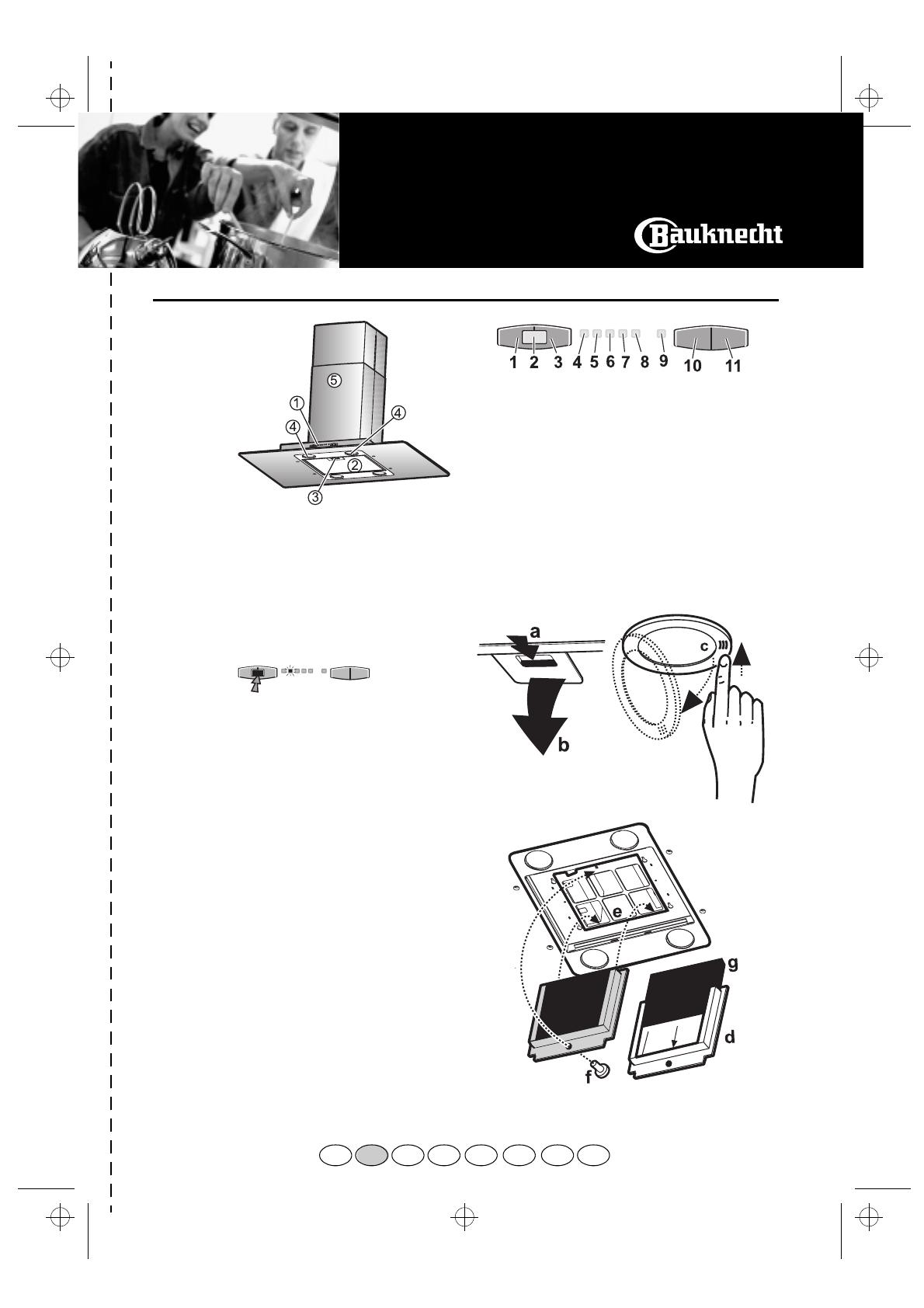
Cleaning the grease filter - Fig. 1
Wash the grease filter at least once a month, or whenever
the grease filter saturation indicator flashes
(Extraction speed indicator light
2
).
1.
Disconnect the electrical power supply.
2.
Remove the grease filters: push the handles back (
a
),
and then downwards (
b
).
3.
After cleaning the grease filter refit in reverse order,
making sure the entire extraction surface is covered.
Resetting the grease filter saturation indicator:
Press the extractor OFF button for three seconds. The grease
filter saturation indicator will stop flashing.
Replacing bulbs - Fig. 2
1.
Disconnect the electrical power supply.
2.
Open the lighting unit by pressing at the reference (
c
),
then turning it outwards.
3.
Replace the burnt-out bulb.
Use 20 W max halogen bulbs only, taking care not to
touch them with hands.
4.
Close the lighting unit (snap-close).
Carbon filter Fitting and Maintenance
Fitting the carbon filter - Fig. 3:
1.
Disconnect the electrical power supply.
2.
Remove the grease filters (
a, b
).
3.
Remove the fixing screw and then the filter holder (
f
).
4.
Fit the carbon filter (
g
) in the filter holder (
d
).
5.
Place the filter holder on the rear tab (
e
), then fix it to
the hood with the screw provided (
f
).
6.
Refit the grease filters.
Carbon filter maintenance:
Unlike traditional carbon filters, this carbon filter can be
washed and reactivated.
With normal hood use, the filter should be cleaned once a
month. The best way to clean the filter is in a dishwasher at
the highest temperature possible, using a normal
dishwasher detergent. To avoid particles of food or dirt
settling on the filter during washing and giving rise to
unpleasant smells, it is advisable to wash the filter on its
own. After washing, dry the filter in the oven at 100° C for
10 minutes to reactivate it.
The filter will retain its odour-absorbing capacity for three
years, after which it must be replaced.
THE CONTROL PANEL
1.
Speed decrease button - 5
Ö
1.
2.
Extraction OFF button.
3.
Extraction ON speed increase button - 0
Ö
5.
4.
Extraction speed indicator
1
.
5.
Extraction speed indicator
2
and grease filter
saturation indicator (when flashing).
6.
Extraction speed indicator
3
.
7.
Extraction speed indicator
4
.
8.
Extraction speed indicator
5
.
9.
Intensive
extraction speed indicator.
10.
Timed intensive speed button.
The hood operates at this speed for 5 minutes and then
returns to the previous settings. This function can be
cancelled by pressing button
1
,
2
or
3
.
11.
Light ON-OFF switch. Press quickly to switch on the
bottom lights only, press and hold for more than 2
seconds to switch on and off the top lamp, which may
be switched on separately from the bottom lamps.
1.
Control panel
2.
Grease filters
3.
Grease filter handles
4.
Bottom halogen bulbs
5.
Telescopic flue
FIG. 1
FIG. 2
FIG. 3
41833000.fm5 Page 9 Wednesday, April 4, 2001 3:45 PM
1 / 1

Bauknecht DDEI 5890 AL Program Chart

Category
Cooker hoods
Type
Program Chart
This manual is also suitable for

Ask a question and I''ll find the answer in the document

Finding information in a document is now easier with AI

Ask the document