Page is loading ...

Read the instructions prior to performing any task!
Assembly and operating instructions
REMKO CMF/CMT 120/160
Inverter heat pumps
Instructions for the Technician
0023-2012-03 Version 1, en_GB

Made by REMKO
Installation and operating instructions (translation of the orig-
inal)
Read these operating instructions carefully before commis-
sioning / using this device!
These instructions are an integral part of the system and must
always be kept near or on the device.
Subject to modifications; No liability accepted for errors or mis-
prints!

Table of contents
1 Safety and user notes........................................................................................................................... 5
1.1 General safety notes....................................................................................................................... 5
1.2 Identification of notes...................................................................................................................... 5
1.3 Personnel qualifications.................................................................................................................. 5
1.4 Dangers of failure to observe the safety notes................................................................................ 5
1.5 Safety-conscious working............................................................................................................... 5
1.6 Safety notes for the operator........................................................................................................... 6
1.7 Safety notes for installation, maintenance and inspection.............................................................. 6
1.8 Unauthorised modification and changes......................................................................................... 6
1.9 Intended use................................................................................................................................... 6
1.10 Warranty........................................................................................................................................ 6
1.11 Transport and packaging.............................................................................................................. 7
1.12 Environmental protection and recycling........................................................................................ 7
2 Technical data....................................................................................................................................... 8
2.1 Units data........................................................................................................................................ 8
2.2 Unit dimenions outdoor modules................................................................................................... 10
2.3 Unit dimensions indoor modules................................................................................................... 11
2.4 Heat pump service limits in monovalent mode ............................................................................. 13
2.5 Pump-characteristic curves, indoor module charging pump......................................................... 14
2.6 Sound pressure level.................................................................................................................... 14
2.7 Overall sound pressure levels for outdoor module ....................................................................... 15
2.8 Annual performance number according to VDI 4650 ................................................................... 17
2.9 Characteristic curves..................................................................................................................... 21
3 Structure and function........................................................................................................................ 27
3.1 The heat pump in general............................................................................................................. 27
3.2 CMF series ................................................................................................................................... 33
3.3 CMT series.................................................................................................................................... 33
4 Installation instructions...................................................................................................................... 34
4.1 System layout................................................................................................................................ 34
4.2 General mountig instructions........................................................................................................ 36
4.3 Installation, mounting indoor module............................................................................................ 37
4.4 Installation, mounting outdoor module.......................................................................................... 38
5 Hydraulic connection.......................................................................................................................... 41
6Corrosion protection.......................................................................................................................... 42
7 Connection of refrigerant lines.......................................................................................................... 43
7.1 Connection of refrigerant lines...................................................................................................... 43
7.2 Commissioning the refrigeration system....................................................................................... 44
8 Elektrical connection.......................................................................................................................... 47
8.1 General notes................................................................................................................................ 47
8.2 Electrical connection - indoor unit................................................................................................. 48
8.3 Electrical connection - outdoor module......................................................................................... 49
8.4 Structure electrical connection...................................................................................................... 51
8.5 Terminal block / legend................................................................................................................. 51
8.6 Connection diagram, terminal configuration.................................................................................. 53
8.7 Circuit diagrams............................................................................................................................ 54
8.8 Auxiliary relays and contactor function.......................................................................................... 64
3

9 Commissioning................................................................................................................................... 65
9.1 Control panel................................................................................................................................. 65
9.2 Notes for commissioning .............................................................................................................. 66
9.3 Heat pump manager Multitalent PLUS (heat flow meters)............................................................ 67
10 Troubleshooting and customer service............................................................................................ 69
11 Exploded view and spare parts......................................................................................................... 72
11.1 Exploded view and spare parts list outdoor modules.................................................................. 72
11.2 Exploded view and spare parts list indoor modules.................................................................... 76
12 Care and maintenance........................................................................................................................ 81
13 Temporary shut-down........................................................................................................................ 81
14 EC- Declaration of Conformity........................................................................................................... 82
15 General terms...................................................................................................................................... 83
16 Index..................................................................................................................................................... 85
REMKO CMF/CMT
4

1 Safety and user notes
1.1 General safety notes
Carefully read the operating manual before com-
missioning the units for the first time. It contains
useful tips and notes such as hazard warnings to
prevent personal injury and material damage.
Failure to follow the directions in this manual not
only presents a danger to people, the environment
and the system itself, but will void any claims for
liability.
Keep this operating manual and the refrigerant
data sheet near to the units.
1.2 Identification of notes
This section provides an overview of all important
safety aspects for proper protection of people and
safe and fault-free operation.The instructions and
safety notes contained within this manual must be
observed in order to prevent accidents, personal
injury and material damage.
Notes attached directly to the units must be
observed in their entirety and be kept in a fully
legible condition.
Safety notes in this manual are indicated by sym-
bols. Safety notes are introduced with signal words
which help to highlight the magnitude of the danger
in question.
DANGER!
Contact with live parts poses an immediate
danger of death due to electric shock. Damage
to the insulation or individual components may
pose a danger of death.
DANGER!
This combination of symbol and signal word
warns of a situation in which there is immediate
danger, which if not avoided may be fatal or
cause serious injury.
WARNING!
This combination of symbol and signal word
warns of a potentially hazardous situation,
which if not avoided may be fatal or cause
serious injury.
CAUTION!
This combination of symbol and signal word
warns of a potentially hazardous situation,
which if not avoided may cause injury or mate-
rial and environmental damage.
NOTICE!
This combination of symbol and signal word
warns of a potentially hazardous situation,
which if not avoided may cause material and
environmental damage.
This symbol highlights useful tips and recom-
mendations as well as information for efficient
and fault-free operation.
1.3 Personnel qualifications
Personnel responsible for operation, maintenance,
inspection and installation must be able to demon-
strate that they hold a qualification which proves
their ability to undertake the work.
1.4 Dangers of failure to observe
the safety notes
Failure to observe the safety notes may pose a risk
to people, the environment and the units. Failure to
observe the safety notes may void any claims for
damages.
In particular, failure to observe the safety notes
may pose the following risks:
nThe failure of important unit functions.
nThe failure of prescribed methods of mainte-
nance and repair.
nDanger to people on account of electrical and
mechanical effects.
1.5 Safety-conscious working
The safety notes contained in this installation and
operating manual, the existing national regulations
concerning accident prevention as well as any
internal company working, operating and safety
regulations must be observed.
5

1.6 Safety notes for the operator
The operational safety of the units and compo-
nents is only assured providing they are used as
intended and in a fully assembled state.
nThe units and components may only be set up,
installed and maintained by qualified per-
sonnel.
nProtective covers (grille) over moving parts
must not be removed from units that are in
operation.
nDo not operate units or components with
obvious defects or signs of damage.
nContact with certain unit parts or components
may lead to burns or injury.
nThe units and components must not be
exposed to any mechanical load, extreme
levels of humidity or extreme temperature.
nSpaces in which refrigerant can leak sufficient
to load and vent. Otherwise there is danger of
suffocation.
nAll housing parts and device openings, e.g. air
inlets and outlets, must be free from foreign
objects, fluids or gases.
nThe units must be inspected by a service tech-
nician at least once annually. Visual inspec-
tions and cleaning may be performed by the
operator when the units are disconnected from
the mains.
1.7 Safety notes for installation,
maintenance and inspection
nAppropriate hazard prevention measures must
be taken to prevent risks to people when per-
forming installation, repair, maintenance or
cleaning work on the units.
nThe setup, connection and operation of the
units and its components must be undertaken
in accordance with the usage and operating
conditions stipulated in this manual and comply
with all applicable regional regulations.
nLocal regulations and laws such as Water
Ecology Act must be observed.
nThe power supply should be adapted to the
requirements of the units.
nUnits may only be mounted at the points pro-
vided for this purpose at the factory. The units
may only be secured or mounted on stable
structures, walls or floors.
nMobile units must be set up securely on suit-
able surfaces and in an upright position. Sta-
tionary units must be permanently installed for
operation.
nThe units and components should not be oper-
ated in areas where there is a heightened risk
of damage. Observe the minimum clearances.
nThe units and components must be kept at an
adequate distance from flammable, explosive,
combustible, abrasive and dirty areas or
atmospheres.
nSafety devices must not be altered or
bypassed.
1.8 Unauthorised modification and
changes
Modifications or changes to units and components
are not permitted and may cause malfunctions.
Safety devices may not be modified or bypassed.
Original replacement parts and accessories
authorised by the manufactured ensure safety. The
use of other parts may invalidate liability for
resulting consequences.
1.9 Intended use
Depending on the model, the equipment and the
additional fittings with which it is equipped is only
intended to be used as an air-conditioner for the
purpose of cooling or heating the air in an
enclosed room.
Any different or additional use shall be classed as
non-intended use. The manufacturer/supplier
assumes no liability for damages arising from such
use. The user bears the sole risk in such cases.
Intended use also includes working in accordance
with the operating and installation instructions and
complying with the maintenance requirements.
Under no circumstances should the threshold
values specified in the technical data be exceeded.
1.10 Warranty
For warranty claims to be considered, it is essential
that the ordering party or its representative com-
plete and return the "certificate of warranty" to
REMKO GmbH & Co. KG at the time when the
units are purchased and commissioned.
The warranty conditions are detailed in the "Gen-
eral business and delivery conditions". Further-
more, only the parties to a contract can conclude
special agreements beyond these conditions. In
this case, contact your contractual partner in the
first instance.
REMKO CMF/CMT
6

1.11 Transport and packaging
The devices are supplied in a sturdy shipping con-
tainer. Please check the equipment immediately
upon delivery and note any damage or missing
parts on the delivery and inform the shipper and
your contractual partner. For later complaints can
not be guaranteed.
WARNING!
Plastic films and bags etc. are dangerous
toys for children!
Why:
- Leave packaging material are not around.
- Packaging material may not be accessible to
children!
1.12 Environmental protection and
recycling
Disposal of packaging
All products are packed for transport in environ-
mentally friendly materials. Make a valuable contri-
bution to reducing waste and sustaining raw mate-
rials. Only dispose of packaging at approved
collection points.
Disposal of equipment and components
Only recyclable materials are used in the manufac-
ture of the devices and components. Help protect
the environment by ensuring that the devices or
components (for example batteries) are not dis-
posed in household waste, but only in accordance
with local regulations and in an environmentally
safe manner, e.g. using certified firms and recy-
cling specialists or at collection points.
7

2 Technical data
2.1 Units data
Series CMF 120 CMT 120 CMF 160 CMT 160
Function Heating or Cooling
System Split-Air/Water
Heat pump manager Multitalent or Multitalent Plus
Storage tank for hydraulic decoupling of volumetric
flows
on-site series
160 l on-site series
160 l
Electric booster heating / rated output kW optional series / 6 optional series / 6
Drinking water heating (switching valve) optional series optional series
Heating capacity min / max kW 3,5 - 11,0 5,0 - 16,0
Heating capacity / compressor frequency / COP 1)
for A10/W35
kW/Hz/
COP 10,5 / 99 / 4,4 15,3 / 76 / 4,7
Heating capacity / compressor frequency / COP 1)
for A7/W35
kW/Hz/
COP 10,0 / 96 / 4,3 13,0 / 77 / 4,4
Heating capacity / compressor frequency / COP 1)
for A2/W35
kW/Hz/
COP 7,2 / 96 / 3,4 9,6 / 76 / 3,2
Heating capacity / compressor frequency / COP 4)
for A2/W35
kW/Hz/
COP 5,1 / 61 / 3,9 6,9 / 51 / 3,4
Heating capacity / compressor frequency / COP 1)
for A-7/W35
kW/Hz/
COP 4,8 / 99 / 2,5 8,2 / 77 / 2,6
Heating capacity / compressor frequency / COP 1)
for A-15/W35
kW/
Hz/
COP
3,8 / 99 / 1,9 5,4 / 77 / 1,7
Heating capacity / compressor frequency / COP 1)
for A7/W45
kW/Hz/
COP 9,4 / 99 / 3,4 13,3 / 76 / 3,4
Heating capacity / compressor frequency / COP 1)
for A2/W45
kW/Hz/
COP 7,0 / 96 / 2,8 9,3 / 76 / 2,5
Heating capacity / compressor frequency / COP 1)
for A-7/W45
kW/Hz/
COP 5,2 / 99 / 2,2 7,4 / 77 / 1,9
Heating capacity / compressor frequency / COP 1)
for A-15/W45
kW/
Hz/
COP
4,3 / 116 / 1,5 4,6 / 77 / 1,2
Heating capacity / compressor frequency / COP 1)
for A20/W55
kW/Hz/
COP 10,4 / 94 / 3,0 12,9 / 61 / 3,4
Heating capacity / compressor frequency / COP 1)
for A7/W55
kW/Hz/
COP 7,9 / 89 / 2,5 9,4 / 61 / 2,5
Heating capacity / compressor frequency / COP 1)
for A-7/W55
kW/Hz/
COP 3,1 / 95 / 1,1 6,1 / 77 / 1,3
Cooling capacity / compressor frequency / EER 2)
for A35/W7
kW/Hz/
EER 5,4 / 70 / 2,9 12,1 / 74 / 3,1
Cooling capacity / compressor frequency / EER 2)
for A27/W7
kW/Hz/
EER 5,9 / 70 / 3,5 12,0 / 69 / 3,7
REMKO CMF/CMT
8

Series CMF 120 CMT 120 CMF 160 CMT 160
Service limits, heating °C -18 - +34
Service limits, cooling °C +15 - +46
Supply-temperature, heating water °C up to +60
Min. Supply-temperature, cooling °C 7
Refrigerant / pre-charge quantity outdoor unit -- / kg R 410A2) / 3,5 R 410A2) / 5,0
Refrigerant / pre-charge quantity for up to 30 m
length of ordinary pipe g / 10m 600
Refrigerant connection Inches 3/8 / 5/8
Max. permissible single refrigerant pipe length. m 50 75
Max. permissible single refrigerant pipe height. m 30
Power supply V / Hz 230 / 1~ / 50 400 / 3~N/ 50
Max. current A 17,5 8,0
Rated current consumption for A7/W35 A 13 5,3
Rated power consumption for A7/W35 kW 2,32 2,95
Power factor by A7/W35 (cosφ) -- 1,0 0,98
Fuse protection (outdoor unit) A slow-
acting 25 3 x 16 A
Rated water flow (acc. to EN 14511, at ∆t 5 K) m³/h 1,7 2,2
Pressure-loss at the condenser at rated flow bar 5,4 8,1
Airflow volume outdoor module m³/h 3300 7200
Max. operating pressure, water bar 3,0
Hydraulic connection, supply / return Inches 1 x OT
Sound-pressure level, LpA 1m (outdoor unit)3) dB(A) 53 / 393) 56 / 423)
Sound-power level in accordance with DIN EN
12102:2008-09 and ISO 9614-2 dB(A) 64,1 67,1
Dimensions, indoor unit (height/width/depth) mm 800/550
/550
1760/550
/670
800/550
/550
1760/556
/610
Dimensions, outdoor unit (height/width/depth) mm 945 / 950 / 330 1338 / 1050 / 330
Enclosure class outdoor unit -- IP 24
Weight indoor module kg 52 135 55 138
Weight outdoor module kg 75 130
1) COP = coefficient of performance or performance number according to EN 14511
2) Contains greenhouse gas according to Kyoto protocol
3) Clear-field distance: 5m
4) COP = coefficient of performance or performance number according to EN 14511, during alternative com-
pressor frequency of the inverter
9

2.2 Unit dimenions outdoor modules
Dimenions outdoor modules CMF/CMT 120
370
600
330
943
950
Fig. 1: Dimenions outdoor modules CMF/CMT 120
Dimenions outdoor modules CMF/CMT 160
1338
1050
370
600
330
Fig. 2: Dimenions outdoor modules CMF/CMT 160
REMKO CMF/CMT
10

2.3 Unit dimensions indoor modules
Dimensions indoor modules series CMF
160
220
255
140
180
550 545
735
300
480
Fig. 3: Dimensions indoor modules series CMF
2
1
4
3
5
6
7
8
Fig. 4: Pipe-socket arrangement
1: Refrigerant pipe, 1/4"
2: Refrigerant pipe, 5/8”
3: Hot-water return, 1” AG
4: Hot-water inlet, 1” AG
5: Sockets for safety assembly
6: Condensate-drain socket AD=22
7: Opening for installing the E-heater controller
8: Fill- and drain valve
50
220
235
155
85
255
200
260
185
150
Fig. 5: Pipe-outlet spacing
11

Dimensions indoor modules series CMT
550 605
910 550
935
1670
180
670
60
100
235
155
80
260
155
2
1
4
3
5
2
3
1
Fig. 6: Dimensions indoor modules series CMT (Tilt height: max. 1,900 mm)
1: Inlet, warm water
2: Inlet, heating
3: Return
4: Refrigerant pipes
5: Overall dimensions: max. 1760
REMKO CMF/CMT
12

2.4 Heat pump service limits in monovalent mode
-18°C; 20°C 3°C; 20°C
2/352/35-15/35
7/452/45-7/45-15/45
20/557/55-7/55
34°C; 32°C
34°C; 58°C
-10°C; 56°C
-16°C; 45°C
-7/35 7/35
10/35
15°C
20°C
25°C
30°C
35°C
40°C
45°C
50°C
55°C
60°C
65°C
-30°C -20°C -10°C 0°C 10°C 20°C 30°C 40°C
VT
[ ° C]
AT
[ ° C]
Fig. 7: Service limits and test points CMF/CMT 120
AT: Outside temperature
VT: Inlet temperature
VT
[ ° C]
AT
[ ° C]
-18°C; 20°C 3°C; 20°C
7/352/352/35-7/35-15/35
7/452/45-7/45-15/45
20/557/55-7/55
10/35
-18°C; 45°C
-10°C; 56°C
34°C; 60°C
34°C; 32°C
15°C
20°C
25°C
30°C
35°C
40°C
45°C
50°C
55°C
60°C
65°C
-30°C -20°C -10°C 0°C 10°C 20°C 30°C 40°C
Fig. 8: Service limits and test points CMF/CMT 160
AT: Outside temperature
VT: Inlet temperature
The left temperature value in the diagrams refers to the outside temperature, the right to the heating
water inlet temperature.
13

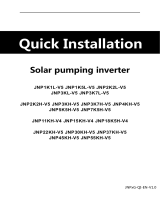
2.5 Pump-characteristic curves, indoor module charging pump
zH 05 ,V 032 x 1 mortsleshceW
ALPHA2 25-40 (A)(N)
ALPHA2 32-40
ALPHA2 25-60 (A)(N)
ALPHA2 32-60
A B
Fig. 9: Pump-characteristic curves, indoor module charging pump
A: Pump-characteristic curves series CMF/CMT 120
B: Pump-characteristic curves series CMF/CMT 160
Character-
istic curves
Level Output [W] Current [A] Motor protection
Amin. 5 0,05 Rotor current-proof
max. 22 0,19 Rotor current-proof
Bmin. 5 0,05 Rotor current-proof
max. 45 0,38 Rotor current-proof
2.6 Sound pressure level
1m1m 5m 10m 1m 5m 10m
Fig. 10: Distance-dependent sound pressure level for the outdoor units in relation to installation type, in
accordance with the drawing
Distance-dependent sound pressure level
Heat pump out-
door unit
Sound power
level according
to ISO 9614-2
Installation type,
in accordance
with the drawing
1m 5m 10m 15m
CMF/CMT 120 64,1 dB(A) In free field 53,1 dB(A) 39,1 dB(A) 33,1 dB(A) 29,6 dB(A)
In front of a wall 56,1 dB(A) 42,1 dB(A) 36,1 dB(A) 32,6 dB(A)
CMF/CMT 160 67,1 dB(A) In free field 56,1 dB(A) 42,1 dB(A) 36,1 dB(A) 32,6 dB(A)
In front of a wall 59,1 dB(A) 45,1 dB(A) 39,1 dB(A) 35,6 dB(A)
REMKO CMF/CMT
14

2.7 Overall sound pressure levels for outdoor module
Overall sound pressure levels for outdoor module CMF/CMT 120
dB
80
30
40
50
60
70
25 63 125 250 500 1000 2000 4000 8000 A L Hz
Cursor:
1
2
Fig. 11: Overall sound pressure level LP CMF/CMT 120
1: Output A-bew
2: Cursor: (A) Power = 64,1 dB
Middle frequency [Hz] 25 31,50 40 50 63 80 100 125 160
LI [dBA] (35,1) (38,0) (38,7) 39,8 40,2 39,6 49,9 37,2 35,6
LWo [dBA] (43,1) (45,9) (46,6) 47,7 48,1 47,5 57,8 45,1 43,5
FPI [dB] -(17,2) -(10,1) -(5,6) -14,2 -11,4 -1,6 4,8 3,6 6,4
Middle frequency [Hz] 200 250 315 400 500 630 800 1000 1250
LI [dBA] 44,5 41,2 42,5 42,9 43,1 44,3 44,4 45,5 43,2
LWo [dBA] 52,4 49,1 50,4 50,8 51,0 52,2 52,3 53,5 51,1
FPI [dB] 5,9 4,7 4,5 5,4 4,8 4,0 3,7 4,1 4,4
Middle frequency [Hz] 1600 2000 2500 3150 4000 5000 6300 8000 10000
LI [dBA] 45,0 43,2 37,5 36,7 34,4 31,2 28,2 (24,1) (22,8)
LWo [dBA] 52,9 51,1 45,4 44,7 42,3 39,1 36,1 (32,0) (30,7)
FPI [dB] 4,6 4,4 3,7 3,7 4,4 4,2 4,0 (3,8) (3,3)
Determination of sound power conforms to accuracy class 2, the standard deviation of the o. a. A-valued
sound-power levels amounts to 1.5 dB
LWo: Sound power level radiated by the outdoor unit
FPI: Correction value with regard to the environment
LI: Sound intensity
15

Overall sound pressure levels for outdoor module CMF/CMT 160
dB
80
30
40
50
60
70
25 63 125 250 500 1000 2000 4000 8000 A L Hz
Cursor:
1
2
Fig. 12: Overall sound pressure level LP CMF/CMT 160
1: Output A-bew
2: Cursor: (A) Power = 67,1 dB
Middle frequency [Hz] 25 31,50 40 50 63 80 100 125 160
LI [dBA] (31,8) -(35,6) (34,6) 40,5 41,5 42,2 40,0 37,6 39,4
LWo [dBA] (41,0) -(44,8) (43,8) 49,7 50,7 51,4 49,2 46,8 48,6
FPI [dB] -(7,9) -(1,4) -(5,5) -9,2 -3,9 0,6 3,3 6,0 6,7
Middle frequency [Hz] 200 250 315 400 500 630 800 1000 1250
LI [dBA] 41,8 50,8 42,6 46,6 47,1 47,9 47,7 46,5 46,1
LWo [dBA] 51,0 60,0 51,8 55,8 56,3 57,1 56,9 55,7 55,3
FPI [dB] 8,7 7,7 9,3 7,6 7,6 6,5 6,3 7,2 7,5
Middle frequency [Hz] 1600 2000 2500 3150 4000 5000 6300 8000 10000
LI [dBA] 45,9 45,4 40,9 37,1 32,4 33,3 25,1 (24,9) (19,9)
LWo [dBA] 55,1 54,6 50,1 46,3 41,6 42,5 34,3 (34,1) (29,1)
FPI [dB] 7,3 7,1 6,6 8,4 10,3 7,3 11,9 (7,2) (6,4)
Determination of sound power conforms to accuracy class 2, the standard deviation of the o. a. A-valued
sound-power levels amounts to 1.5 dB
LWo: Sound power level radiated by the outdoor unit
FPI: Correction value with regard to the environment
LI: Sound intensity
REMKO CMF/CMT
16

2.8 Annual performance number according to VDI 4650
Mode: single energy source, parallel with a switch-over point of -5°C
Climatic region: -10°C
Old house with domestic hot-water heating (share 18%)
Type
COP by compressor rated
frequency
Annual performance
number with inlet/outlet
temperature differential: 7K
and inlet temperature...
Annual performance
number with inlet/outlet
temperature differential:
10K and inlet temperature...
A-7/
W35
A2/W35 A10/
W35
30°C 35°C 40°C 45°C 50°C 55°C
CMF/CMT 120 2,48 3,44 4,41 3,82 3,71 3,60 3,56 3,44 3,32
CMF/CMT 160 2,57 3,24 4,72 3,74 3,63 3,52 3,49 3,37 3,25
New construction with hot-water heating (share 18%)
Type
COP by compressor rated
frequency
Annual performance
number with inlet/outlet
temperature differential: 7K
and inlet temperature...
Annual performance
number with inlet/outlet
temperature differential:
10K and inlet temperature...
A-7/
W35
A2/W35 A10/
W35
30°C 35°C 40°C 45°C 50°C 55°C
CMF/CMT 120 2,48 3,44 4,41 3,71 3,59 3,48 3,44 3,31 3,19
CMF/CMT 160 2,57 3,24 4,72 3,59 3,48 3,37 3,33 3,21 3,09
Climatic region: -12°C
Old house with domestic hot-water heating (share 18%)
Type
COP by compressor rated
frequency
Annual performance
number with inlet/outlet
temperature differential: 7K
and inlet temperature...
Annual performance
number with inlet/outlet
temperature differential:
10K and inlet temperature...
A-7/
W35
A2/W35 A10/
W35
30°C 35°C 40°C 45°C 50°C 55°C
CMF/CMT 120 2,48 3,44 4,41 3,73 3,62 3,51 3,48 3,36 3,24
CMF/CMT 160 2,57 3,24 4,72 3,65 3,54 3,43 3,40 3,28 3,17
New construction with hot-water heating (share 18%)
Type
COP by compressor rated
frequency
Annual performance
number with inlet/outlet
temperature differential: 7K
and inlet temperature...
Annual performance
number with inlet/outlet
temperature differential:
10K and inlet temperature...
A-7/
W35
A2/W35 A10/
W35
30°C 35°C 40°C 45°C 50°C 55°C
CMF/CMT 120 2,48 3,44 4,41 3,63 3,51 3,40 3,36 3,24 3,12
CMF/CMT 160 2,57 3,24 4,72 3,51 3,40 3,29 3,25 3,14 3,02
17

Climatic region: -14°C
Old house with domestic hot-water heating (share 18%)
Type
COP by compressor rated
frequency
Annual performance
number with inlet/outlet
temperature differential: 7K
and inlet temperature...
Annual performance
number with inlet/outlet
temperature differential:
10K and inlet temperature...
A-7/
W35
A2/W35 A10/
W35
30°C 35°C 40°C 45°C 50°C 55°C
CMF/CMT 120 2,48 3,44 4,41 3,68 3,57 3,47 3,43 3,32 3,29
CMF/CMT 160 2,57 3,24 4,72 3,59 3,49 3,38 3,35 3,24 3,13
New construction with hot-water heating (share 18%)
Type
COP by compressor rated
frequency
Annual performance
number with inlet/outlet
temperature differential: 7K
and inlet temperature...
Annual performance
number with inlet/outlet
temperature differential:
10K and inlet temperature...
A-7/
W35
A2/W35 A10/
W35
30°C 35°C 40°C 45°C 50°C 55°C
CMF/CMT 120 2,48 3,44 4,41 3,57 3,46 3,35 3,32 3,20 3,09
CMF/CMT 160 2,57 3,24 4,72 3,46 3,52 3,25 3,21 3,10 2,99
Climatic region: -16°C
Old house with domestic hot-water heating (share 18%)
Type
COP by compressor rated
frequency
Annual performance
number with inlet/outlet
temperature differential: 7K
and inlet temperature...
Annual performance
number with inlet/outlet
temperature differential:
10K and inlet temperature...
A-7/
W35
A2/W35 A10/
W35
30°C 35°C 40°C 45°C 50°C 55°C
CMF/CMT 120 2,48 3,44 4,41 3,59 3,49 3,38 3,35 3,24 3,13
CMF/CMT 160 2,57 3,24 4,72 3,52 3,42 3,32 3,29 3,18 3,07
New construction with hot-water heating (share 18%)
Type
COP by compressor rated
frequency
Annual performance
number with inlet/outlet
temperature differential: 7K
and inlet temperature...
Annual performance
number with inlet/outlet
temperature differential:
10K and inlet temperature...
A-7/
W35
A2/W35 A10/
W35
30°C 35°C 40°C 45°C 50°C 55°C
CMF/CMT 120 2,48 3,44 4,41 3,37 3,15 3,26 3,23 3,12 3,00
CMF/CMT 160 2,57 3,24 4,72 3,27 3,07 3,18 3,14 3,04 2,92
Note: A differential of 7K has a standard floor-heating layout, a differential of 10K is typical for a radiator
system
Additional key data: a heating-threshold temperature of 15°C for old construction and 12°C in new construc-
tion, a differential at the condenser (test-bench measurements: 5K)
REMKO CMF/CMT
18

Mode: bivalent-parallel with a switch-over point of -3°C
Climatic region: -10°C
Old house with domestic hot-water heating (share 18%)
Type
COP by compressor rated
frequency
Annual performance
number with inlet/outlet
temperature differential: 7K
and inlet temperature...
Annual performance
number with inlet/outlet
temperature differential:
10K and inlet temperature...
A-7/
W35
A2/W35 A10/
W35
30°C 35°C 40°C 45°C 50°C 55°C
CMF/CMT 120 2,48 3,44 4,41 4,05 3,93 3,80 3,76 3,62 3,48
CMF/CMT 160 2,57 3,24 4,72 3,96 3,84 3,71 3,67 3,54 3,41
New construction with hot-water heating (share 18%)
Type
COP by compressor rated
frequency
Annual performance
number with inlet/outlet
temperature differential: 7K
and inlet temperature...
Annual performance
number with inlet/outlet
temperature differential:
10K and inlet temperature...
A-7/
W35
A2/W35 A10/
W35
30°C 35°C 40°C 45°C 50°C 55°C
CMF/CMT 120 2,48 3,44 4,41 3,92 3,79 3,66 3,62 3,48 3,34
CMF/CMT 160 2,57 3,24 4,72 3,79 3,66 3,54 3,49 3,36 3,22
Climatic region: -12°C
Old house with domestic hot-water heating (share 18%)
Type
COP by compressor rated
frequency
Annual performance
number with inlet/outlet
temperature differential: 7K
and inlet temperature...
Annual performance
number with inlet/outlet
temperature differential:
10K and inlet temperature...
A-7/
W35
A2/W35 A10/
W35
30°C 35°C 40°C 45°C 50°C 55°C
CMF/CMT 120 2,48 3,44 4,41 3,96 3,83 3,70 3,66 3,53 3,40
CMF/CMT 160 2,57 3,24 4,72 3,86 3,73 3,61 3,57 3,45 3,32
New construction with hot-water heating (share 18%)
Type
COP by compressor rated
frequency
Annual performance
number with inlet/outlet
temperature differential: 7K
and inlet temperature...
Annual performance
number with inlet/outlet
temperature differential:
10K and inlet temperature...
A-7/
W35
A2/W35 A10/
W35
30°C 35°C 40°C 45°C 50°C 55°C
CMF/CMT 120 2,48 3,44 4,41 3,83 3,70 3,57 3,53 3,40 3,26
CMF/CMT 160 2,57 3,24 4,72 3,70 3,57 3,45 3,41 3,28 3,15
19

Climatic region: -14°C
Old house with domestic hot-water heating (share 18%)
Type
COP by compressor rated
frequency
Annual performance
number with inlet/outlet
temperature differential: 7K
and inlet temperature...
Annual performance
number with inlet/outlet
temperature differential:
10K and inlet temperature...
A-7/
W35
A2/W35 A10/
W35
30°C 35°C 40°C 45°C 50°C 55°C
CMF/CMT 120 2,48 3,44 4,41 3,89 3,77 3,65 3,61 3,48 3,36
CMF/CMT 160 2,57 3,24 4,72 3,79 3,67 3,56 3,52 3,40 3,27
New construction with hot-water heating (share 18%)
Type
COP by compressor rated
frequency
Annual performance
number with inlet/outlet
temperature differential: 7K
and inlet temperature...
Annual performance
number with inlet/outlet
temperature differential:
10K and inlet temperature...
A-7/
W35
A2/W35 A10/
W35
30°C 35°C 40°C 45°C 50°C 55°C
CMF/CMT 120 2,48 3,44 4,41 3,77 3,56 3,52 3,48 3,35 3,22
CMF/CMT 160 2,57 3,24 4,72 3,64 3,52 3,40 3,37 3,24 3,12
Climatic region: -16°C
Old house with domestic hot-water heating (share 18%)
Type
COP by compressor rated
frequency
Annual performance
number with inlet/outlet
temperature differential: 7K
and inlet temperature...
Annual performance
number with inlet/outlet
temperature differential:
10K and inlet temperature...
A-7/
W35
A2/W35 A10/
W35
30°C 35°C 40°C 45°C 50°C 55°C
CMF/CMT 120 2,48 3,44 4,41 3,79 3,67 3,56 3,52 3,40 3,27
CMF/CMT 160 2,57 3,24 4,72 3,71 3,59 3,48 3,45 3,33 3,20
New construction with hot-water heating (share 18%)
Type
COP by compressor rated
frequency
Annual performance
number with inlet/outlet
temperature differential: 7K
and inlet temperature...
Annual performance
number with inlet/outlet
temperature differential:
10K and inlet temperature...
A-7/
W35
A2/W35 A10/
W35
30°C 35°C 40°C 45°C 50°C 55°C
CMF/CMT 120 2,48 3,44 4,41 3,66 3,54 3,42 3,38 3,26 3,13
CMF/CMT 160 2,57 3,24 4,72 3,55 3,43 3,32 3,28 3,17 3,04
Note: A differential of 7K has a standard floor-heating layout, a differential of 10K is typical for a radiator
system
Additional key data: a heating-threshold temperature of 15°C for old construction and 12°C in new construc-
tion, a differential at the condenser (test-bench measurements: 5K)
REMKO CMF/CMT
20
/